and non-linear controllers that respond adequately to the dynamics of the system, which is extremely unstable since, in open loop small plate inclinations.
A Sliding-Mode Controller from a Reduced System Model: Ball and Plate System Experimental Application Luis Morales, Oscar Camacho, Paulo Leica and Danilo Chávez Departamento de Automatización y Control Industrial, Escuela Politécnica Nacional Ladrón de Guevara, E11-253, Quito, Ecuador
Keywords:
Ball-Plate System, Sliding-Mode Control, PID Controller, Stabilization, Reduced System Model.
Abstract:
The purpose of this work is to design a Sliding-Mode Control from a reduced system model using a PID as sliding surface. The controller is applied to a Ball and Plate system which has extremely non-linear characteristics and therefore does not have a unique solution in terms of ball stabilization control. The results are obtained by simulations and with real experiments in the implemented system. A comparative performance analysis is done between the proposed approach and a PID controller to stabilize the ball at fixed points of the plate.
1
INTRODUCTION
The Ball and Plate system is an extension of the ballbeam system, which has 2 degrees of freedom and due to its non-linear characteristics has generated interest in the study and analysis of classic, modern and non-linear controllers that respond adequately to the dynamics of the system, which is extremely unstable since, in open loop small plate inclinations cause indefinite displacement of the ball. The system has two actuators that allow to vary the inclination of the plate to stabilize the ball or to track paths. Stabilization means keeping the ball in a desired position and following path demands making the ball follow a geometric pattern regardless of time. The system modeling is obtained easily (Nokhbeh and Khashabi, 2011), therefore, different works has focused on analyzing the response of controllers in order to stabilize the ball on the platform (Bay and Rasmussen, 2016); the high nonlinearity of the system implies that there is no a unique satisfactory solution. Several experiments have been developed in order to control the system; The typical experiment is with the classic PID controller. (Ali and Aphiratsakun, 2016), whose parameters tuning is done through methods such as Ziegler-Nichols, Tyreus-Luyben and heuristic (Aphiratsakun and Otaryan, 2015). It is not necessary to know the mathematical model of the plant to determine best controller tunings Kp, Ki and
Kd, to stabilize the ball on the plate in the shortest time as possible, and reducing oscillations. In (Knuplei et al., 2003), a lead controller is proposed, however, the controller does not present good results since there is a considerable error in steady state. Nonlinear controllers based on Lyapunov´s stability (Wang et al., 2008) have been tested in the platform with different frictions and it is evidenced that this parameter affects the performance of the controller considerably. Fuzzy controllers are applied in (Fan et al., 2004), with the purpose of moving the ball through the track of a path, taking the ball from point A to point B without crashing obstacles on the plate. Sliding-Mode Control (SMC) is also used for stabilization control, the results of (Debono and Bugeja, 2015) evidence an improvement in the system response, however the controller employs complex trigonometric calculations (Valadez et al., 2014). Due to robustness of SMC, it can attenuate the uncertainty in the measurement of the ball’s position, and it allows to stabilize the ball in less time and with fewer oscillations. Previous works have shown an important amount of results in stabilization tasks for the ball and plate system using PID and SMC controllers. Different to those papers, the purpose of this work is to design a Sliding-Mode Control from a reduced system model using a PID as sliding surface. The resulting controller is simple and robust without complex calculations reducing computational
590 Morales, L., Camacho, O., Leica, P. and Chávez, D. A Sliding-Mode Controller from a Reduced System Model: Ball and Plate System Experimental Application. DOI: 10.5220/0006425905900597 In Proceedings of the 14th International Conference on Informatics in Control, Automation and Robotics (ICINCO 2017) - Volume 1, pages 590-597 ISBN: 978-989-758-263-9 Copyright © 2017 by SCITEPRESS – Science and Technology Publications, Lda. All rights reserved
A Sliding-Mode Controller from a Reduced System Model: Ball and Plate System Experimental Application
cost and easy implementation (Camacho and Smith, 2000). The results are obtained by simulations and with real experiments in the implemented system. A comparative performance analysis is done between the proposed approach and a PID controller to stabilize the ball at some fixed points of the plate. This paper is organized as follows. Section 2 briefly presents the mathematical model of the plant. Section 3, presents some basic concepts of the SMC method and its design. Section 4, the simulation and experimental tests are presented and a comparison is made between the performance of the conventional PID and the SMC with the PID sliding surface. Section 5, presents the conclusions of the work.
2 2.1
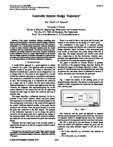
The plant has a camera with a resolution of 640x640 pixels that acquires images at a 30 fps to determine the position of the ball and feedback the control loop (Figure 2). Image processing has algorithms for ball detection, and has implemented a Kalman Filter for noise elimination (Cedeño and Gordón, 2016).
MATHEMATICAL MODEL Ball and Plate System
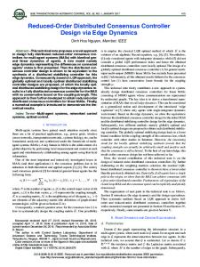
The ball and plate system consists of a rigid platform, in which the ball rolls, two servo motors (actuators) that allow to vary the inclination angles, a camera that allows feedback the system with the position of the ball in the X and Y axes, and the control system as shown in Figure 1.
Figure 2: Experimental Ball and Plate System.
2.2
Mathematical Model
The mathematical model of the plant shown in Figure.2., neglecting the surface friction and applying the Lagrange method (Fan et al., 2004) is:
(1)
0
0 Figure 1: Schematic diagram of the ball and plate system.
In Figure 1, α is the angle of the plate in X-axis, β is the angle of Y-axis, ux and uy are control actions applied to actuators for X-axis and Y-axis respectively. The plant has been designed, built and implemented in the Laboratory of Automatic Control at Escuela Politécnica Nacional. The platform has a glass surface to minimize friction and to be able to despise the frictional forces and simplify model calculation and is controlled by two servo motors to adjust the inclination of the X-axis and the Y-axis.
(2)
Table 1, presents the description of the parameters of equations (1) and (2). Table 1: Parameters of the mathematical model. Symbol
Parameters of Ball and Plate System Units Description kg Mass of the ball kg cm2 Moment of inertia of the ball cm Radius of the ball cm Position of the ball in the X-axis cm Position of the ball in the Y-axis rad Angle of the plate from X-axis rad Angle of the plate from Y-axis kg m/s2 Acceleration due to gravity
591
ICINCO 2017 - 14th International Conference on Informatics in Control, Automation and Robotics
2.3
Reduced System Model
Considering small angle of inclination of the plate (±8° = ±0.139 rad), this movement is slow to stabilize the ball on the plate, therefore: ≅ 0 , ≅ 0 (Nokhbeh and Khashabi, 2011), thus is obtained: (3)
(4)
Where: , are the positions of the ball in the , are X-axis and Y-axis respectively, and the rotation angles of servo motors of the plant.
3
This work proposes two methods to stabilize the ball on a desired position of the plate: the PID controller and the SMC method with sliding surface PID, to finally compare its performance.
3.1 2.3.1 Linearized Model Linearizing equations (3) and (4) by Taylor Series at the operating point 0, ̅ 0 when the platform is in horizontal position and keeps the ball in equilibrium, the following equations were obtained: (5)
(6) Considering
the
gravity
980
moment of inertia of a solid ball
, :
(7)
700
(8)
Plate´s angles and actuators’ rotation angles are related by the following equations: (9)
(10) 10 , are the rotation angles of the Where: servomotors. Substituting (9) and (10) in (7) and (8) respectively gives: 70
(11)
70
(12)
Laplace transform of the model is calculated: 70 70
592
PID Controller
To stabilize the ball on a plate position two independent controllers have been designed, one for X-axis and another for Y-axis of similar characteristics due to the symmetry of the system. Heuristically calibrates the parameters of the controller in the real plant starting from the values given by the auto-tuning method of a computational software until obtaining the lowest ISE, index used to measure the performance of controllers (Kealy and O’dwyer, 2003) and defined for a period of time as shown in (15). (15)
and
700
10
CONTROLLER’S DESIGN
(13) (14)
, is Where: 20 (time of the experiment), the error between reference and output in the X-axis, establishing the constant values for the controllers of the X-axis and Y-axis 0.035, 0.018, 0.073. 0.0001,
3.2
Sliding-Mode Control
Sliding-Mode Control (SMC) is based off the idea of variable structure control. One of the main applications of the SMC method is non-linear systems since robustness to uncertainty is indispensable in the field of control systems. This method proposes to define a surface along which the process can slide until reaching a final value. Control law of SMC is: (16) Uc is the continuous part of the control that allows to stay on the sliding surface, and Ud is the discontinuous part of the control that allows to reach the sliding surface. (Slotine and Li, 1991) proposes the surface shows in (17): (17)
A Sliding-Mode Controller from a Reduced System Model: Ball and Plate System Experimental Application
Where: is the sliding surface, surface order and is the error.
3.3
is the sliding
/2
(27)
Stability condition denotes that:
SMC Method Design
The following procedure has been presented by (Camacho and Smith, 2000), in which the mathematical model of a PID controller is taken as the sliding surface. The design of the controller for the X-axis is presented, since the Y-axis has the same characteristics due to the symmetry of the system. The PID controller for X-axis is:
(18)
0
(28)
Substituting (24) in (28), gives: 70
0
(19)
2
Substituting (26) in (29) and simplifying, gives: 70
0
(30)
To perform the condition of (30) is proposed: Discontinues part incorporates a nonlinear element that includes the switching element of the control law. This part of the controller is discontinuous across the sliding surface. (Camacho and Smith, 2000), propose:
Then, is considered the PID as a sliding surface since they have the same mathematical form. (20)
|
∴
|
Substituting (32) in (26), the control law is:
0:
0
|
(22)
Deriving error in X-axis the following is obtained:
70
(21) 0,
(32)
0
Controller (16), for X-axis is: is computed considering
(29)
(31)
2, with (18):
Comparing (17) for
Considering a Lyapunov function:
(33)
|
In (Camacho, 1996), is shown the derivatives of the reference value can be discarded, without any effect on the control performance, resulting a simpler controller for X and Y axis:
(23) Substituting (23) in (22), gives: 70
0
(24)
|
(34)
|
Substituting the model of the plant in X-axis (11) in is computed: (24), 70
(35)
(25) 70 Substituting (25) in (21), gives:
70 For the calculation of discontinues part analyzed Lyapunov´s stability.
(26) , is
Based on the Lyapunov’s stability analysis, these → 0, → 0 when → ∞. controllers guaranteed Calibrating values to obtain the lowest index, experimentally is determined 0.93, and 0.75 observing that this value eliminates the chattering and produces an adequate response of the system. These values were obtained for a step
593
ICINCO 2017 - 14th International Conference on Informatics in Control, Automation and Robotics
0.065. The designed reference obtaining controller scheme is shown in Figure. 4.
plate’s central point. Figure 6 and 7, show ball’s position on X and Y-axis vs. time and Figure 8., shows the ball’s movement on the plate.
Figure 4: Proposed control scheme.
Figure 6: Simulated ball position on the X-axis.
This section presents the comparison between both controllers, first, by simulation, and finally the experimental results are presented in the laboratory plant shown in Figure. 2. To analyze the performance of the controllers, measurement indexes are used.
4 4.1
RESULTS Simulation Results
First, the ball stabilization test is performed at the plate’s central point whose coordinate is (23 [cm], 23 [cm]), starting from the initial position (0 [cm], 0 [cm]). Figure 5, illustrates how perform each controller. It shows the ball position on the X-axis vs. time, the response on the Y-axis does not presented since it is similar, in simulation cases.
Figure 7: Simulated ball position on the Y-axis.
Figure 8: Simulated movement of the ball on the plate to reach the four square vertices.
Figure 5: Simulated ball position on the X-axis.
Results obtained for reaching a sequence of points corresponding to the vertices of a square 20 [cm] per side, are presented in Figures 6, 7 and 8, starting from 594
SMC method allows to reach the desired position smoother, faster and with lower overshot, since the control action is not as abrupt as in PID controller. Performance by index of the two controllers is shown in Table 2. Settling time has been measured once the system response is within a band of 5% of the reference value.
A Sliding-Mode Controller from a Reduced System Model: Ball and Plate System Experimental Application
Table 2: Simulation controller’s comparison using measurement parameters.
POINT SQUARE VERTICES
PID SMC Δ% PID SMC Δ%
PERFORMANCE COMPARISON INDEXES ISE Settling Overshoot time (s) (%) 0.041 4.0 25.3 0.036 3.2 18.0 12.9% 22.2% 33.7% 0.044 4.7 26.5 0.041 3.5 19.1 7.0% 29.2% 32.4%
There is a considerable difference between the measured indicators, the most representative is the settling time and overshot, showing that designed SMC allows to obtain better results than PID controller for ball’s stabilizing.
4.2
Experimental Results
Experimental results are obtained using the real plant. The ball stabilization test is performed at the central point of the implemented system whose coordinate is (23 [cm], 23 [cm]), from the position (0 [cm], 0 [cm]), this is done for the X and Y-axis. Ball’s position is shown in Figure. 9 and 10. In Figure. 11., ball’s movement on the plate is shown.
Figure 11: Experimental movement of the ball on the plate to stabilize the ball at point (23 [cm], 23 [cm]).
Results obtained for reaching four vertices of a square 20 [cm] starting from position (23 [cm], 23 [cm]) are presented in Figures. 12, 13 and 14. SMC method reaches the reference points with a better performance since its control action is less abrupt as shown in Figure 15.
Figure 12: Experimental ball position on the X-axis.
Figure 9: Experimental ball position on the X-axis.
Figure 13: Experimental ball position on the Y-axis.
The vibrations in the response of the system are due to mechanical limitations since the plate is placed on a central pivot axis. Figure 10: Experimental ball position on the Y-axis.
595
ICINCO 2017 - 14th International Conference on Informatics in Control, Automation and Robotics
[cm/s], a greater one becomes the system unstable, while the SMC allows to reach the maximum velocity of the ball of 52 [cm/s]. It is evident that the ISE is lower for all cases with SMC method.
Figure 14: Experimental movement of the ball on the plate to reach the four square vertices. Figure 16: controllers.
Robustness
comparison
between
both
Second robustness analysis was performed with balls of different mass and radius determining the of each controller as shown in the Table 4. Table 4: Experimental controller’s comparison using measurement parameters for different balls.
Figure 15: Control Action for X-axis. Table 3: Experimental controller’s comparison using measurement parameters.
POINT SQUARE VERTICES
PID SMC Δ% PID SMC Δ%
PERFORMANCE COMPARISON INDEXES Settling time Overshoot ISE (s) (%) 0.073 2.7 20.8 0.065 1.2 5.2 11.6% 76.9% 120% 0.096 2.3 23.7 0.082 1.1 9.5 15.7% 70.5% 85.5%
The most representative values are the settling time and the overshot, demonstrating that the SMC approach allows to obtain better results in this system in a high variation. It is also observed in the graphs there is a delay in the action of the actuators of 0.4 [s] which could be reduced with a dead time scheme controller that improves the system response.
4.3
PID SMC Δ% PID SMC Δ% PID SMC Δ%
ISE 0.074 0.064 14.1% 0.063 0.052 19.1% 0.082 0.070 15.7%
Figures 17 and 18, show the behavior of the balls in the X-axis with the PID controller and the SMC approach respectively, evidencing that the proposal of this work improves its stabilization in the best of cases up to 19%. Balls 1 and 2, are easy to stabilize due to their weight and size, however ball 3 being lighter before a small vibration, its position changes in a more sensitive way, SMC presents a minor error in steady state.
Robustness Analysis
The first robustness analysis of both controllers is shown in Figure. 16., in which the ISE value can be calculated by testing the ball stabilization at different initial velocities before a step input. The maximum initial velocity of the ball in the case of the PID is 42 596
Ball 1 Mass = 129[g] Radius = 17 [mm] BALL 2 Mass = 20 [g] Radius = 13 [mm] BALL 3 Mass = 5 [g] Radius = 8 [mm]
Figure 17: Experimental ball position on the X-axis for 3 balls stabilizing by PID controller.
A Sliding-Mode Controller from a Reduced System Model: Ball and Plate System Experimental Application
Figure 18: Experimental ball position on the X-axis for 3 balls stabilizing by SMC proposed approach.
5
CONCLUSIONS
The results obtained through simulation are similar to those obtained experimentally, which demonstrate that the performance of the SMC method is better than PID, since it allows to stabilize the ball in a shorter time decreasing the considerably the overshot. The methodology proposed in this work allows the design of controllers based on Sliding-Mode through a PID sliding surface, controllers that in most applications present excellent results, and whose performance can be improved by applying this technique providing robustness to the control system without complex calculations. To design this controller, it is indispensable to know the mathematical model of the plant, and its constants must be calibrated adequately.
ACKNOWLEDGEMENTS Oscar Camacho thanks PROMETEO project of SENESCYT, Republic of Ecuador, for its sponsorship for the realization of this work. Authors thank to PIJ-15-17 Project of Escuela Politécnica Nacional for its sponsorship for the realization of this work.
Bay, C., & Rasmussen, B. (2016). Exploring Controls Education: A Re-Configurable Ball and Plate Platform Kit. Retrieved from http://oaktrust.library.tamu.edu/ handle/1969.1/156115 Camacho, O. (1996). A New Approach to Design and Tune Sliding Mode Controllers for Chemical Processes, PhD dissertation. University of South Florida, Tampa, Florida. Camacho, O., & Smith, C. (2000). Sliding mode control: an approach to regulate nonlinear chemical processes. ISA Transactions, 39(2), 205–18. https://doi.org/10.1016/ S0019-0578(99)00043-9 Cedeño, A., & Gordón, M. (2016). Implementación de una plataforma de estabilización para control de posición y seguimiento de camino de una esfera. Final Career Project. Escuela Politécnica Nacional, Quito-Ecuador. Retrieved from http://bibdigital.epn.edu.ec/handle/ 15000/16909 Debono, D., & Bugeja, M. (2015). Application of Sliding Mode Control to the Ball and Plate Problem. 12th International Conference on Informatics in Control, Automation and Robotics (ICINCO), 412–419. Fan, X., Zhang, N., & Teng, S. (2004). Trajectory planning and tracking of ball and plate system using hierarchical fuzzy control scheme. Fuzzy Sets and Systems, 144(2), 297–312. https://doi.org/10.1016/S0165-0114(03) 00135-0 Kealy, T., & O ’dwyer, A. (2003). Analytical ISE Calculation And Optimum Control System Design. _Issc. Retrieved from http://arrow.dit.ie/engscheleart Knuplei, A., Chowdhury, A., & Sveeko, R. (2003). Modelling and Control design for the ball and plate system. 2003 IEEE International Conference on Industrial Technology, 1064–1067. https://doi.org/ 10.1109/ICIT.2003.1290810 Nokhbeh, M., & Khashabi, D. (2011). Modelling and Control of Ball-Plate System Final Project Report. Slotine, J., & Li, W. (1991). Applied Nonlinear Control. Prentice Hall, New Jersey. Valadez, H., Loukianov, A., Castillo, B., & BayroCorrochano, E. (2014). Sliding control variation for ball-plate system stabilization. 13th International Workshop on Variable Structure Systems (VSS). Wang, H., Tian, Y., Fu, S., & Sui, Z. (2008). Nonlinear control for output regulation of ball and plate system. Proceedings of the 27th Chinese Control Conference, CCC, 382–387. https://doi.org/10.1109/CHICC.2008. 4605473
REFERENCES Ali, E., & Aphiratsakun, N. (2016). AU ball on plate balancing robot. 2015 IEEE International Conference on Robotics and Biomimetics, IEEE-ROBIO 2015, 2031–2034. https://doi.org/10.1109/ROBIO.2015.7419 072 Aphiratsakun, N., & Otaryan, N. (2015). Ball On The Plate Model Based on PID Tuning Methods * A. AU Ball On The Plate Balancing Robot, (1), 3–6.
597