A Software Architecture for Physical Layer ... - Semantic Scholar
Recommend Documents
Email: [email protected]. AbstractâThis paper1 presents a coding scheme for the Gaus- sian wiretap channel based on low-density parity-check (LDPC) codes.
Sep 18, 2015 - New cloud service offerings and revenue opportunities can be ... agnostic, the test bed illustrates the co-existence of VMware and .... the network into zones should also reduce the management traffic load ... use a combination of inba
systems and digital electronics nodes that sense, compute and ... used for illustration throughout the paper. The rest of the paper ..... Tutorials 7.2 (2005): 72-93.
Abstractâ Software architecture as an important branch of software ... advantages and disadvantages. For sure ... management and security that has made this architecture ..... EDBT workshop on Software engineering for tailor-made data.
We informally introduce TaxLog, a close integration of logic programming and .... CDn. Function- free. Definite. Horn. Clauses. - concrete domains. - layer of fast ...
Abstractâ Software architecture as an important branch of software ..... of software such as capability of development reliance and security capability by.
Jun 21, 2013 - ney, Australia (Email: shuang.tian, yonghui.li, mahyar.shirvanimoghaddam, ... need to know the channel state information before sending its encoded symbols ...... We can observe that the proposed scheme has the best perfor- mance for .
We optimize the task and message design with respect to this metric by ... the software or hardware architecture that requires the replace- .... The search space consists of the pri- ..... they will be set to 0 by the optimization engine, unless forc
2.1). Mobile software systems must in particular cope with the network's dynamics (§ 2.2) and quality of service management, as the mobile environment makes ...
Shared environments beyond the desktop supporting face-to-face collaboration put new requirements on software: Users interact with multiple devices, and.
Abstract. A Software Architecture Supporting Networked Sensors by. Jason Hill. Master of Science in Electrical Engineering and Computer Science. University of ...
quests for those services from its client(s). We are confronted with the following questions: how can we evolve a given software architecture to make it compliant ...
Oct 10, 2007 - sion in âmega data centersâ and blade servers, which have new and broad potential .... quired to cover the legacy LAN/MAN market (10-Gb Eth-.
software architecture can exist in different phases of the whole software lifecycle [Christine 2000]. RSA describes SA at ... the software release. Moreover, the ...
Abstract. We present a domain-specific software architecture (DSSA) that supports development of a variety of intelligent patient monitoring (IPM) agents through.
Dec 10, 2014 - level infrastructure is in place, machines can register into the network and exchange .... waiting to be tapped. Deutsche Bank Research.
Dec 10, 2014 - Moreover, by utilizing advanced information analytics, networked machines will be able to perform more efficiently, collaboratively and ...
synchronization system based on hierarchical clock distribution via Ethernet and an .... narrowing the local clock period, but clock frequency restrictions limit the ...
Integrated Media Systems Center / Institute for Robotics and Intelligent Systems ... stone of this architecture is the Flow Scheduling Framework (FSF), an extensible set of .... We define a structure that we call pulse, as a carrier for all the data
domain-specific software architecture (DSSA) that we have developed for a large ... computational framework for a significant domain of applications, (b) a ...
domain by complementing other approaches, simply by adding mobility of ... name agency, which is responsible to execute agents, pro- vide an environment .... kernel, several additional software components, where each component provides a ... vice com
Media Independent Handover (MIH) services has been .... Mobility Manager for handling not only handover, but also power management and adaptation.
Aug 25, 2010 - Chalmers Univ. of Technology/Göteborg University, Sweden .... 3 Classes of Architectural Design Decisions. We now want to talk about the ..... AUTomotive open system ARchitecture (AUTOSAR), 2009. [3] Anton Jansen ...
Jul 17, 2000 - the existing advantage of libraries to which scientific programmers are so ... Thus, programmers must recode their application to optimize the ...
A Software Architecture for Physical Layer ... - Semantic Scholar
A Software Architecture for Physical Layer Wireless Network Emulation. Glenn Judd and ... Our emulator consists of both custom and commodity hard- ware that must .... An alternative design would be to use a scripting language such as TCL.
A Software Architecture for Physical Layer Wireless Network Emulation Glenn Judd and Peter Steenkiste∗ Carnegie Mellon University Pittsburgh, PA, USA [email protected][email protected] Abstract Despite their widespread deployment, many aspects of wireless network performance are poorly understood, and there is great room from improvement in wireless network reliability and performance. A key obstacle to understanding and improving wireless networks has been the lack of a realistic yet flexible experimental methodology. Physical layer wireless network emulation promises to achieve much of the flexibility of wireless simulators while maintaining much of the realism of real wireless networks. We have developed a software architecture that tames the complexity of physical layer wireless network emulation, and presents users with a powerful yet ease-to-use interface. We present several case studies showing how this software architecture allows complex wireless experiments to be conducted in an efficient manner while still enabling novice users to quickly run simple experiments.
Categories and Subject Descriptors C.2 [Computer Systems Organization]: Computer-computer Communication
Over the last decade, wireless networks have been deployed at an explosive rate. The exciting capabilities made possible by the inexpensive ubiquity of wireless networking technology has lead ∗ This research was funded in part by the NSF under award numbers CCR-0205266 and CNS-0434824. Additional support was also provided by Intel and Xilinx.
Permission to make digital or hard copies of all or part of this work for personal or classroom use is granted without fee provided that copies are not made or distributed for profit or commercial advantage and that copies bear this notice and the full citation on the first page. To copy otherwise, to republish, to post on servers or to redistribute to lists, requires prior specific permission and/or a fee. WiNTECH’06, September 29, 2006, Los Angeles, California, USA. Copyright 2006 ACM 1-59593-538-X/06/0009 ...$5.00.
to a massive amount of activity in the research community to improve the performance of existing wireless networks and develop new applications based on this technology such as mesh and intervehicular networks. Conducting wireless research is, nonetheless, a challenging endeavor due to the distributed and ephemeral nature of wireless signal propagation. Thus, while hardware-based experimentation clearly achieves the most physical layer realism, practical considerations such as ease of development, control, and experimental repeatability have made simulation the dominant experimental technique. Recent work [1], however, has shown that unless a great deal of care is taken, simulation-based research can produce imprecise and even inaccurate results. While careful simulation setup is a necessary condition for producing valid experimental results, it is clearly not sufficient in and of itself. A more fundamental condition that must be met to achieve valid wireless networking simulation results is the use of an accurate simulator. Not only must this simulator have a correct networking protocol stack, but it must accurately reproduce wireless signal transmission, propagation, and reception. As wireless signal reception behavior is only completely accurate when using real hardware, wireless simulations will always be a coarse approximation. We have developed a wireless emulator [2, 3] that enables both realistic and repeatable wireless experimentation by supporting accurate wireless signal transmission, propagation, and reception in an emulated physical space. Unlike previous approaches, this emulator utilizes a real MAC layer, a real PHY layer, and supports real applications while avoiding adopting an uncontrollable or locale-specific architecture. The key technique we use to accomplish this is digital emulation of signal propagation using an FPGA. Our emulator allows signal propagation to be modeled in several ways: first, widely used statistical models of signal propagation can be used; in addition, traces of observed signal propagation can be “replayed” on our emulator; lastly, manual control of signal propagation can be used to analyze behavior in artificially created situations that would be difficult or impossible to reproduce using other techniques. The emulator provides an attractive middle ground between pure simulation and wireless testbeds. To a large degree, this emulator maintains the repeatability, configurability, isolation from production networks, and manageability of simulation while retaining the support for real applications and much of the realism of hardware testbeds. As a result, this emulator can be a superior platform for wireless experimentation. Our emulator consists of both custom and commodity hardware that must act in concert to enable users to accurately emulate arbitrary signal propagation environments and efficiently execute experiments. Developing software to achieve this has been a challenging task. This paper discusses the software architecture that
enables our physical layer wireless emulator to achieve accurate emulation while enabling efficient experimentation. Our discussion proceeds as follows. Section 2 gives an overview of our emulator’s architecture and implementation. Section 3 compares and contrasts the requirements of our emulator with the capabilities of existing network simulators and emulators. Section 4 discusses our software architecture in detail. Section 5 then presents several case studies of how our software architecture allows various experiments to be conducted on the emulator, and Section 6 concludes.
2.
High-level Architecture Emulation Controller
Network Devices
Wireless Network Emulator
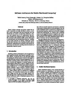
Figure 1. Emulator Architecture The high-level architecture of our emulator is shown in Figure 1. A number of “RF nodes” (e.g. laptops, access points, cordless phones, or any wireless device in the supported frequency range) are connected to the emulator through a cable attached to the antenna port of their wireless line cards (each RF node corresponds to a single antenna, so a single device can be represented by multiple RF nodes). The RF nodes are shielded from each other so that no communication occurs over the air. All communication between RF nodes occurs through the signal propagation environment modeled within the emulator. That is, we achieve via digital signal processing the same physical effects that occur in the real world: attenuation, multipath, interference, etc. This allows us to use real commercial wireless networking hardware, running on a real device, with a real OS, and real applications. Emulation is controlled by an Emulation Controller PC which models the physical environment and coordinates the movement of RF nodes in the modeled physical environment with the modeling of the signal propagation environment on the emulator hardware. Emulation occurs in real time. Thus, the emulator supports both real wireless devices and real applications operating as if they were actually in the emulated environment.
Implementation Emulation Controller
Signal Conversion
Signal Conversion DSP Engine FPGA-based
Signal Conversion
Emulator Architecture and Implementation
Before discussing the software architecture, we give a brief overview of the hardware on which the software operates. For a more complete introduction to physical layer wireless network emulation see [2] where this approach is introduced, validated, and contrasted with other approaches. [2] also addresses the issue of signal propagation environment modeling.
2.1
2.2
Signal Conversion
Network devices and signal conversion modules reside in shielded chassis.
Figure 2. Emulator Implementation Figure 2 shows the implementation of the high-level architecture discussed above. This implementation supports any RF device in the 2.4 GHz ISM band. On transmit, the RF signal from a given RF node is passed into the signal conversion module where it is shifted down to a lower frequency, digitized, and then forwarded in digital form into a central DSP Engine that is built around one or more FPGAs. The DSP Engine models the effects of signal propagation (e.g. large-scale attenuation and small-scale fading) on each signal path between each RF node. Finally, for each RF node, the DSP combines the processed input signals from all the other RF nodes. For each RF node, the resulting signal is then sent out to the signal conversion module which converts the digital signal back to a radio signal. It is then sent to the wireless line card through the antenna port. Our current DSP Engine supports up to 15 wideband RF nodes. Using multiple DSP Engines larger systems can be built. The Emulation Controller controls RF node movement in the emulated physical environment as well as application behavior on the end hosts. Movement within the physical environment is emulated in real time; the controller coordinates this movement with the real-time modeling of the signal propagation environment. Each RF node runs a small daemon that allows the Emulation Controller to control its operation via a wired network. A proxy can be used for nodes that cannot run the daemon themselves. Connecting the Emulation Controller to an external network allows remote management of the emulator. In addition, individual nodes in the emulator may be connected to external networks in order to allow emulator nodes access to the Internet at large or to allow the emulator to be used in conjunction with testbeds such as PlanetLab [4], Emulab [5], or Orbit [6].
3.
Emulation Software Requirements
Before discussing the software architecture of our emulator, we briefly consider the requirements that real-time physical emulation imposes on the software that supports it. We also consider how the capabilities of existing simulators and emulators compare to our requirements. At a high level, our emulator performs modeling similar to that of traditional wireless simulators. Like traditional wireless simulators, we can model a physical environment with wireless devices distributed in it, and path loss between devices. Traditional simulators, however, also must model the behavior of the transmitter
radio and MAC, the receiver radio and MAC, the network stack, and applications running on the network. Physical network emulation - in contrast - removes the need to model any of these since the wireless devices are real from the application layer to the radio. Our use of real devices and real applications is similar to that found in other emulators such as Emulab [5], Orbit [6], Modelnet [7], or Mint-b [8]. Like these systems, we must control real devices and the applications that run on them in real time. Our emulator and these systems, however, differ greatly in both their mechanism for modeling signal propagation environments and the range of environments that they are capable of modeling. Like our emulator, Emulab supports real wireless devices, but in a testbed fashion; i.e. the wireless network is hardwired to a particular physical location. Orbit is also a testbed, but attempts to emulate different physical environments through selection of nodes positioned in a grid and the injection of noise to alter signal-to-noise ratios and mimic the effect of path loss; the techniques used in this approach are very different from those that can be leveraged in our system. Mint-m and Emulab also use robots to introduce mobility; while this introduces mobility, the emulated signal environment cannot be altered and is still bound to the room in which the robots reside. Earlier work [9] proposed using coaxial cables to hardwire a custom signal propagation environment. While useful for very limited experiments, our approach allows for vastly improved flexility, scale, mobility and complete signal control. Modelnet, makes use of real end hosts, but does not make use of real wireless devices, preferring to simulate their behavior. Our system requires a software infrastructure that is - in some ways - a hybrid of traditional network simulation and emulation. Like other systems, we are using real devices; unlike other systems, however, we have full control over the physical signal propagation between between the devices attached to our network. This is enabled by our unique hardware which contains a powerful digital signal processing platform capable of digitizing and manipulating signals streaming between all wireless devices attached to it. A key requirement of our software is to make use of this signal processing platform to accurately emulate signal propagation in a controlled manner. At the lowest level, this requires software to control the signal processing. In our case, this low-level software is written using a hardware description language (HDL). (As this code is reconfigurable, we will refer to this HDL code as software.) No existing wireless network simulator or emulator contains software for this fine-grained level of signal processing. Moreover, we desire our system to be more general than typical wireless network simulators. ns-2’s wireless support, for instance, was originally developed with the assumption that ad hoc routing was the problem of interest; we make no assumption about the problem or even the devices attached to our system (as long as they fall in our supported frequency band.) Thus mixing devices of different technologies is supported with no additional effort. In contrast, a traditional packet simulator with n different types of devices will need to resolve the O(n2 ) possible interactions between these deivces In addition, we remove the assumption that a physical world is necessarily being modeled. That is, we allow users to directly control the signal propagation channels between devices without necessarily considering a physical world. This is similar to “multipath fading simulators” [10, 11] that are commercially used to evaluate RF devices. Fading simulators, however, are severely limited in the number of channels that they support and are not capable of modeling an entire network.
4.
Software Architecture
As alluded to in the previous section, controlling real-time physical layer wireless network emulation is a complex task that requires careful real-time coordination of several hardware devices and the software distributed in them. At the same time, the complexity of the emulation must be shielded from users as much as possible; to accomplish this, we present users with a simple interface that makes the emulator appear largely like a traditional wireless network simulator. This provides a familiar experimental interface.
Emulation Controller Physical World
Java
Signal Environment
Hardware Configuration
Emulation Controller/RF Nodes Node Control
Auxiliary FPGA
DSP Engine
DSP Support
Signal Processing
C
Execution Control
Signal Conversion Module Signal Conversion
HDL
Figure 3. Software Architecture Overview Figure 3 depicts the major systems in the software architecture of our emulator; system names are shown in shaded boxes. The software systems are grouped according to the language in which they are written; the italicized labels identify the hardware components in which the software systems reside. The remainder of this section will discuss each of the software systems depicted in the figure.
4.1
Execution Control
The execution control system is responsible for controlling all other systems according to the users’ intentions. It allows users to control the emulator via three interfaces: scripts that provide an easy-to-use method for conducting simple experiments, programs that provide more advanced users with powerful control, and a graphical user interface that enables interactive experimentation as well as visualization. Scripts. The script interface is an easy-to-use interface for conducting basic experiments. This interface allows users to define node movement and application execution without the need to write real code. The scripting interface that we provide is deliberately simple. No looping, branching, or variables are supported. Rather scripts are defined as lists of events using an XML-based syntax. This restricted interface provides a very shallow learning curve, and makes writing basic emulator experiments an easy task. An alternative design would be to use a scripting language such as TCL. We avoid this since 1 - it does not eliminate the need for a compiled programming interface for advanced access to the core of the simulator; it simply adds a new language that must be learned, and 2 - the need to access core emulator functionality from the scripting language would quickly lead to a bloated scripting interface and complex coupling with the programmatic interface.
Hence our design maintains the key benefit of scripting - the ability to run simple experiments - while supporting full programmatic control in a clean manner. Programs. Experiments that have requirements exceeding the capabilities of the script interface utilize the programmatic interface. The control code running on the Emulation Controller is written in Java. Users may write Java classes that are loaded at emulation boot time and then have full access to the emulator code. Using the programmatic interface, experiments with arbitrarily complex behavior can be created in a straightforward fashion. Again, as the scripted interface does not maintain emulator state, there is virtually no coupling between user scripts and core emulator code. GUI. When conducting experiments with real hardware in a physical environment, there is frequently an exploration phase during which wireless nodes are moved and applications are run in an interactive fashion. For instance, a transmit rate selection experiment between a laptop and an access point would likely include a phase where the laptop was moved around and performance observed in an interactive fashion. After initial performance was observed, then strict procedures would be followed for formal results gathering. One unique aspect of our emulator is the ability to perform this exploratory phase without the need to actually move around the real world. To support this type of functionality, we provide an interactive GUI (Figure 4) that can be used to move RF nodes around in an emulated physical environment and in the corresponding emulated signal propagation environment.
Signal Environment Channel… Physical World
Source Antenna… EmuNode… NIC… Antenna…
4.2
Physical World
The physical world system is responsible for managing physical objects in the emulated physical environment. In particular, the physical world controls the movement of EmuNodes which represent wireless devices. The structure of the Physical World system is shown in Figure 5(a). Each EmuNode may have one or more wireless NICs, and each NIC has one or more antennas. Antennas connect the physical world with the signal propagation environment as discussed in the following section. Each antenna corresponds to a single RF node in the general architecture picture. Hence each EmuNode may be represented by multiple RF nodes.
Destination Antenna… Path… Loss Model Fading Model delay
a)
b)
Figure 5. Physical World and Signal Environment As EmuNodes move in the physical environment, their antennas move and the corresponding signal environment modules are informed of the movement.
4.3
Signal Environment
Signal propagation modeling is controlled by the SignalEnvironment system which is structured as shown in Figure 5(b). Between each pair of antennas in the wireless system, there exist two channels - one in each direction. Each channel consists of one or more signal paths. Each path has a propagation delay, a loss model, and a fading model associated with it. The loss model defines large-scale path loss (a fixed attenuation that does not change unless RF node movement is emulated) between the destination and source antennas. A typical loss-model will register itself with the physical world so that whenever the source or the destination antennas move, loss is recomputed. The fading model defines small-scale fading (rapid variation in signal strength that can occur even if the device antennas are motionless) between the source and destination antennas. A typical fading model will register its interest in velocity changes of the source and destination antennas. It then uses the velocities of the two antennas to compute small-scale signal strength variations which are added on top of the large-scale path loss.
4.4
Figure 4. Interactive GUI
Path-based Channel Model
Hardware Configuration
The hardware configuration code is divided into two portions. The first portion manages information about the physical hardware setup (the hardware configuration.) It keeps track of the number of emulated nodes in the system, the identities of the circuit boards used to emulate each node, etc. The second portion manages the software used for signal processing on the DSP engine (the software configuration.) This module reads the emulation hardware configuration specification and generates HDL code to implement the channels models on the DSP engine. This code generation is necessary since the HDL code used by the DSP Engine (see below) changes based on the simulation environment specified by the user.
4.5
Signal Processing
The Signal Processing HDL code is responsible for performing the processing required by the channel modeling code discussed earlier. Figure 6 shows the operation of the Signal Processing code. Incoming signals are first sent into a delay line where one or more copies (“taps”) of the signal are pulled off after going
sf Input 1
sf
Delay Pipe
sf Input 2
…
…
Output 1
5.1
sf
Delay Pipe
case studies. These examples do not cover the all of our software architecture’s functionality, but have been chosen to illustrate a range of ways in which the user is able to utilize the system.
TCP Throughput vs. Distance
Output 2 TCP
sf Input 3
…
sf
Delay Pipe
Output 3
20
40
60
80
Figure 6. DSP Engine Operation
Figure 7. Throughput vs. Distance Topology
through a programmable amount of delay. Each of these signals is then scaled by a programmable factor computed from the sum of large-scale path loss and small-scale fading. Each outgoing signal, from the FPGA to an RF node, is then computed by summing the scaled signals from the other RF nodes. These outgoing signals are then sent to the D/A board for reconstruction. The programmable nature of this circuit allows us to trade off resources such as the precise depth of the delay pipes and number of signal copies supported. Thus, we can customize the operation of the DSP Engine to the particular test being run. For each signal path inside of the DSP Engine, the Emulation Controller is capable of dynamically adjusting both the attenuation and delay from the source to the destination by dynamically setting the scaling factors and delay mentioned previously at a rate of over one thousand times per second. Hence, for each signal path, the emulator can recreate effects such as large-scale path loss and fading.
We first demonstrate how our emulator’s software architecture facilitates conducting simple experiments. Specifically, we consider a simple TCP throughput vs. distance experiment where TCP throughput is measured at a small number of locations in an emulated environment. This is a straightforward experiment, and the emulator’s script interface provides a simple means of implementing it. For this experiment, we desire to use a modeled signal propagation environment where all channels are modeled using a single path with log-distance large-scale path loss and Rayleigh fading. This signal propagation environment is defined as follows in the software configuration specification:
4.6
DSP Support
The DSP Support code acts as an intermediary between the Java-based code on the Emulation Controller and the HDL code on the DSP Engine. It translates high level requests into hardware instructions. Likewise, it allows the HDL code to send messages to the Java-based code on the Emulation Controller. In addition, this DSP support code provides access to an embedded processor that can be leveraged to assist both the Emulation Controller and DSP Engine in tasks such as channel modeling.
4.7
Signal Conversion Module
The signal conversion module converts between the RF signals used by the wireless devices and the digital signals processed by the emulator. On transmit, signals digitized by the A/D converter must be sent to the DSP Engine. On receive, signals from the DSP Engine must be sent to the D/A. Also, for testing and other purposes it is useful to allow signals to bypass the DSP and be sent directly from the A/D to the D/A. We achieve this functionality through the use of an FPGA on each signal conversion module. Hence, the signal conversion module software is written to accomplish this routing of signals in this FPGA. Moreover, the signal conversion software has the ability to process signals outside of the main DSP. Thus effects such as noise generation can be offloaded from the DSP Engine.
5.
Case Studies
To illustrate how our software architecture enables users to easily conduct a broad range of experiments, we present a series of
Default 1 40.0 2.8 3.0 In this experiment, we measure TCP throughput between two wireless NICs at four different distances in our emulated environment. This is done as follows (we use pseudo-code in square brackets to abridge for brevity): emu-1 0.0 0.0 0.0 emu-1 iwconfig wlan0 essid test mode ad-hoc channel 6 [add node 2 and run iwconfig on it] emu-1 tcpThroughputServer
emu-2 tcpThroughputClient emu-1 emu-2 40.0 0.0 0.0 ... In short, this test has shown how a simple experiment can be conducted with minimal effort.
5.2
Hidden Terminal Throughput
Node 1
In the hidden case, we set the attenuation between 1 and and 3 to be infinite. This is done by simply adding the following to the above definitions: Infinity [use same definition for 3 to 1] Bandwidth tests may then be conducted for each of these situations in a manner similar to the TCP Throughput example. As stated above, the key point of this example is to show how manual control of the signal propagation environment is easily specified, and can be used to obtain useful results.
Node 2 70 dB
70.0
70 dB
In range: 90 dB
5.3
Hidden: Infinite
The previous tests have illustrated modeled or manually specified signal propagation environments. An alternative to modeling wireless channel conditions is to record a real wireless channel and then to replay that channel in the emulator. We now show how our software infrastructure easily incorporates traces of wireless channel behavior and corresponding device location traces. Channel traces consist simply of time-stamped path loss values, and can be gathered using commodity wireless hardware. A portion of an actual pathloss trace gathered by a major automobile manufacturer is shown below:
Node 3
Figure 8. Hidden Terminal Topology The hidden terminal problem is a well known problem in wireless networks. To measure the impact of this problem on real hardware, it is useful to deliberately create a hidden node situation and run throughput tests. Despite the conceptual simplicity of this task, investigating hidden node performance with real hardware in a real physical environment is very difficult. Our emulator’s complete control over signal propagation makes this difficult problem trivial by enabling complete control over wireless channels. Moreover, our software architecture allows this experiment to be constructed in a straightforward manner. This example illustrates our emulator’s ability to directly control channel conditions without the need to worry about the physical environment. In other words, in this experiment there is no physical environment, just a manually specified signal propagation environment. We create the desired signal propagation environment by manually specifying attenuation between RF nodes to create the in range and hidden node topologies shown in Figure 8. In both cases, two nodes - 1 and 3 - communicate with a third node - 2 - over channels with a single path and 70 dB of attenuation. In the in-range case, we set the attenuation between 1 and 3 to be 90 dB. The in-range channel signal environment definitions are as follows: Default
Vehicular Convoy Channel Replay
1-2 2700 -104.000000 -99.000000 ... For further details on obtaining channel traces see [12]. Channel traces can be combined with node mobility traces gathered using a localization system such as GPS. The below trace is an excerpt of a location trace gathered in conjunction with the loss trace shown above: 1 51835.325630 4432.397624 0.0 38.000000
51835.391262 4430.662439 0.0 38.201000 ...
test was repeated for all combinations of RSS values from Ta and Tb at R between -102 and -72 dBm in 1 dBm intervals. An excerpt from our code is shown below: // set attenuation to infinity mPathController.setAllPathsOff(); [start traffic sources]
// set attenuation to infinity mPathController.setAllPathsOff(); // gather results
As a final example of how our software infrastructure enables our emulator to conduct insightful experiments, consider a case from our own research; we desired to measure 802.11b packet capture behavior (packet capture is reception in spite of interfering signals). To do this we used the emulator’s manual channel control interface. This allowed us to reason directly about the channel conditions without worrying about what physical environment might create such a channel. As our channel required a large number of configurations, we leveraged our software infrastructure’s programmatic interface. The setup for this experiment is shown in Figure 9. The goal of this experiment was to establish the reception outcome given the RSS at a receiver R from transmitters Ta and Tb without controlling precisely for interference timing. That is, we didn’t control when packets from Ta and Tb arrived at receiver R. In both configurations shown in Figure 9, the tests proceeded as follows: two transmitters Ta and Tb constantly sent broadcast packets at a very high rate to the receiver R. At first, the channels were all “turned off” in the emulator so that no packets were actually received at R. While the channels were “off” the traffic sources were started. We then simultaneously turned on the channels and set the RSS at R from each transmitter to the desired values. In the “hidden” configuration, we did not allow Ta and Tb to hear each other’s transmissions. In the “in-range” setup the RSS from Ta to Tb was set at -80 dBm and vice versa, so that Ta and Tb always heard each other’s transmissions. After a fixed time interval, the channels from Ta and Tb to R were shut off. R then recorded how many packets it received from each transmitter. This
-110
In-range
Figure 9. Capture Topology
-115
Hidden
Tb
Ta
-100
Tb
-105
Ta
R
-90
R
-95
Programmatic Channel Control
-80
5.4
// set attenuation from transmitters->rcvr. // uplinkRSS[] is the current RSS to be used for (int i = 0; i < uplinkRSS.length; i++) { mPathController.setPathRSS(txNodes[i], destNode, 0, txPowerdBm, txRSS[i]); mPathController.setPathRSS( destNode, txNodes[i], 0, txPowerdBm, txRSS[i]); } // set attenuation between transmitters for (int i = 0; i < txNodes.length; i++) { for (int j = 0; j < txNodes.length; j++) { if (i != j) { if (runningHiddenTest) { // turn channel off between // transmitters mPathController.setPathRSS( txNodes[i], txNodes[j], 0, txPowerdBm, Double.NEGATIVE_INFINITY); } else { // set attenuation between // transmitters mPathController.setPathRSS( txeNodes[i], txNodes[j], 0, txPowerdBm, interferenceRSS); } } } } // wait for traffic to be sent/received Thread.sleep(trafficDurationMillis);
-85
One application of trace record and playback is intervehicular communication. Major automobile manufacturers are working to equip vehicles with short range wireless networks. As part of this effort, they are gathering traces of intervehicular pathloss and corresponding location traces. Replaying these path loss traces within our emulator allows us conduct an experiment multiple times while varying experimental parameters - such as the routing algorithm. By replaying the exact same signal trace, we are able to evaluate the desired experimental aspect without the need to worry about channel variations across runs. In contrast, conducting a similar comparison using real world experiments is next to impossible since even if we drove our cars over the same route, large amounts of channel variation would occur across experiments.
Physical layer wireless network emulation promises to combine much of the flexibility of traditional wireless network simulation with much of the realism of testbed-based experimentation. Coordinating the operation of a physical network emulator in realtime is a complex task. We have presented a software architecture that manages the complexity of physical network emulation while presenting users with a powerful yet easy-to-use interface. We have shown through a series of case studies how this software architecture allows a wide variety of wireless experiments to be conducted in an efficient manner. This architecture provides the basis for quickly conducting realistic wireless experiments in a flexible manner.
Source 1 uplink rss
Figure 11. Packet Capture: Hidden Figures 10 and 11 shows results of these tests for 1 Mbps. In each of these figures the z-axis is the number of packets received from both Ta and Tb at R. In many RSS combinations, however, packets were actually only received from one or the other; the regions where one source or the other dominated are labeled on the plots. In all in-range cases, when the RSS at R from both Ta and Tb was high, CSMA did a good job of allowing the two nodes to share the medium, and only a small number of collisions occurred. When one transmitter was out of range of R and the other was in range, the number of packets received for the in-range cases was roughly half of the channel capacity since the reception between Ta and Tb is still good, and they defer for each other’s transmissions irrespective of the number of packets successfully received at R. An important question is what happens when transmissions from two nodes overlap in time at a single receiver. The “hidden node” configuration tests investigate this question. In hidden node situations, Ta and Tb send at full rate since they are out of carrier sense range. Looking at the 1 Mbps results, collisions only occur for a very narrow range of signal strengths where the RSS at R is nearly identical from both Ta and Tb. These tests (and similar results for other rates) show that for low transmission rates, collisions occur only when the received signal strengths of the competing signals at a receiver are nearly equal. Hence, packets sent at low rates - in particular beacons, RTS, CTS, and ACK - are very robust to interference. Thus, deferring transmission due to an interfering source below the capture threshold is not necessary and hurts network performance. Our emulator’s precise programmatic control over channels was key in allowing us to precisely characterize reception behavior of commodity devices and gain insight into packet capture behavior in the presence of competing 802.11b signals.
7.
References
[1] S. Kurkowski, T. Camp, and M. Colagrosso. Manet simulation studies: The incredibles. Mobile Computing and Communications Review pp. 50–61, October 2005. [2] G. Judd and P. Steenkiste. Using Emulation to Understand and Improve Wireless Networks and Applications. Proceedings of NSDI 2005, May 2005. [3] G. Judd and P. Steenkiste. Repeatable and realistic wireless experimentation through physical emulation. HotNetsII, November 2003. [4] L. Peterson, T. Anderson, D. Culler, and T. Roscoe. A blueprint for introducing disruptive technology into the internet. Proc. of HotNets-I, October 2002. [5] B. White, J. Lepreau, L. Stoller, R. Ricci, S. Guruprasad, M. Newbold, M. Hibler, C. Barb, and A. Joglekar. An integrated experimental environment for distributed systems and networks. Proc. of OSDI 2002, December 2002. [6] D. Raychaudhuri, I. Seskar, M. Ott, S. Ganu, K. Ramachandran, H. Kremo, R. Siracusa, H. Liu, and M. Singh. Overview of the ORBIT Radio Grid Testbed for Evaluation of Next-Generation Wireless Network Protocols. Proc. of WCNC 2005., March 2005. [7] P. Mahadevan, K. Yocum, and A. Vahdat. Emulating large-scale wireless networks using modelnet. Poster and Abstract Mobicom 2002, September 2002. [8] P. De, R. Krishnan, A. Raniwala, K. Tatavarthi, N. Syed, J. Modi, and T. Chiueh. MiNT-m: An Autonomous Mobile Wireless Experimentation Platform. Proc. of Mobisys 2006, June 2006. [9] J. Kaba and D. Raichle. Testbed on a Desktop: Strategies and Techniques to Support Multi-hop MANET Routing Protocol Development. Proc. of Mobihoc 2001, October 2001. [10] PROPSim. Propsim c8 wideband multichannel simulator, http://www.propsim.net/. [11] Spirent Communications. Tas4500 flex5 rf channel emulator, http://www.spirent-communications.com/. [12] G. Judd and P. Steenkiste. A simple mechanism for capturing and replaying wireless channels. E-Wind 2005, August 2005.