Mar 19, 2015 - A software controlled voltage tuning system using multi-purpose ring ...... terisation of device speed, accounting for process variation across ...
A software controlled voltage tuning system using multi-purpose ring oscillators Steve Kerrison and Kerstin Eder University of Bristol {steve.kerrison,kerstin.eder}@bristol.ac.uk
arXiv:1503.05733v1 [cs.OH] 19 Mar 2015
March 2015 increased transistor counts, helps to reduce power by needing a lower operating voltage than the previous generation of devices. However, the relationship between feature size, power and performance becomes more complex and subject to greater variability with smaller process technologies, and so feature size alone cannot be relied upon to improve both performance and power. Techniques such as Dynamic Voltage and Frequency Scaling (DVFS) [BPSB00], power- and clock-gating, and advanced sleep states [ANDS06] are used in combination with operating systems and application software to ensure energy consumption is minimised whilst delivering sufficient performance for a set of tasks. In order for a processor manufacturer to ship a product and guarantee reliability, it must select operating parameters that will enable the product to function correctly in spite of any process variation across the range of parts. As such, the operating voltages in the product data sheet must be chosen with a degree of conservatism. Additionally, products may be binned into different speed or power categories, depending on their behaviour under test, but there will still be variation, even across the binned parts, which presents challenges in categorising parts reliably [SPKG10]. Ring Oscillators (ROs) are free-running logic blocks that operate at a frequency governed by the delays intrinsic to their structure and also the behaviour of the silicon within which they are implemented. Therefore, their behaviour varies from chip to chip. This can be exploited in various ways, for example as a random number seed, or for clock generation. In this paper, ROs combined
Abstract This paper presents a novel software driven voltage tuning method that utilises multi-purpose Ring Oscillators (ROs) to provide process variation and environment sensitive energy reductions. The proposed technique enables voltage tuning based on the observed frequency of the ROs, taken as a representation of the device speed and used to estimate a safe minimum operating voltage at a given core frequency. A conservative linear relationship between RO frequency and silicon speed is used to approximate the critical path of the processor. Using a multi-purpose RO not specifically implemented for critical path characterisation is a unique approach to voltage tuning. The parameters governing the relationship between RO and silicon speed are obtained through the testing of a sample of processors from different wafer regions. These parameters can then be used on all devices of that model. The tuning method and software control framework is demonstrated on a sample of XMOS XS1-U8A-64 embedded microprocessors, yielding a dynamic power saving of up to 25% with no performance reduction and no negative impact on the real-time constraints of the embedded software running on the processor.
1 Introduction Modern embedded computing systems require ever-increasing performance from microprocessors whilst simultaneously consuming less energy. Progress in both of these areas leads to new opportunities in embedded applications. Advances in silicon fabrication technologies bring shrinks in feature size, which along with
1
with hardware counters are used to determine the most appropriate operating voltage for a processor given the observed RO speed and the desired operating frequency. The XMOS XS1-U8A-64 processor is used as the test subject for this technique, by virtue of its voltage scaling capabilities and RO implementation. The ROs are embedded in the processor silicon, but are separate components within the processor accessible via software and so can be considered multi-purpose. This paper makes the following contributions to the areas of energy efficient embedded software/hardware co-design and embedded processor architectures:
desired outcome and typically measured in Joules. Power dissipation is an instantaneous measure of a rate of energy transfer, expressed in Watts. Power dissipation at 1 Watt for 1 second results in an energy consumption of 1 Joule. The majority of this paper refers to power, rather than energy, for consistency.
2 Background This paper builds upon research into and application of techniques in the areas of CMOS device properties, voltage and frequency scaling, and ROs. This section covers the relevant background within these three areas.
• A unique application of multi-purpose software-controlled ROs, rather than custom hardware blocks.
2.1 Power dissipation and DVFS • A flexible soft control loop for voltage tuning a system, that is both process variation and temperature sensitive.
The technique of Dynamic Voltage and Frequency Scaling (DVFS) is motivated by a desire to minimise energy consumption in a device by operating in the most efficient possible trade-off of power vs. performance for a given workload [BPSB00]. DVFS is affected mainly by two components of power dissipation in a CMOS device: static and dynamic power.
• The control method, although implemented in software, has zero impact on the timing of an application running on the processor. • Granularity of control is unconstrained in software as characterisation formulae are used rather than a table of operating states. • The method’s power saving capabilities are demonstrated, through testing and evaluation on a set of samples of the target device.
Static power The main component of static power is the leakage current of the transistors in the silicon. This is present regardless of the on/off state of transistors. As processors are fabricated on smaller process nodes, the percentage of overall power dissipation that is attributed to leakage is growing [KABM03], for example due to increased leakage through thinner gate oxide layers, which must be combated with technology such as improved high-k gate dielectrics [WWA01].
The rest of this paper is organised as follows. Section 2 explores frequency and voltage scaling, existing voltage tuning approaches including methods for evaluating the silicon speed, and uses of ROs in processors. In Section 3 a new tuning approach is described in the context of the chosen target hardware. Section 4 shows the results of testing this technique on a sample of target processors. An evaluation of the technique’s effectiveness is presented in Section 5, followed by discussion of future work in Section 6 and conclusions in Section 7. For clarity, this paper refers to energy and power in terms of consumption and dissipation respectively. That is, energy consumption is a measure of total work done — the amount of potential that is transformed in order to achieve the
Ps = V Ileak
(1)
In Equation 1, the static power, Ps , is the product of the device voltage, V , and the leakage current, Ileak . Thus, there is a simple linear relationship between operating voltage and static power.
2
Dynamic power Power dissipated in order to switch transistors on or off is termed dynamic power, Pd , and is expressed in Equation 2. Pd = αCsw V 2 F
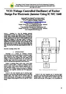
Figure 1: Basic construction of a ring oscillator, with feedback of output Q to the first inverter in the chain. Wire lengths and the number of inverters affect the oscillator frequency.
(2)
Csw is the capacitance of the transistors in the device and α is an activity factor or the proportion of them that are switched. Activity factor is workload specific, but often estimated as switching half of the transistors in the device [BTM00], giving α = 0.5. F is the operating frequency of the device. Observe that changes in V have the biggest influence on dynamic power dissipation. A reduction in V , however, will slow the transistor switching speed, increasing the delay in the critical path, requiring that F also be lowered. Thus, there is a trade-off between reduced power dissipation and the total energy consumption due to longer execution time — in some cases it is not beneficial to slow the device down further. Choosing a strategy for energy saving, be it tuning the frequency to avoid slack time, or racing to idle by operating at high speed briefly, then reducing to a low power state, is dependent on the type of work and the behaviour of the system; there is not one strategy that works in all cases [ANG08]. The relationship between voltage and frequency varies depending on manufacturing process and device implementation. Simplistic representations, such as that in [KABM03], represent the th relationship as F ∝ V −V , where Vth is the threshV old voltage of the transistor. As V approaches Vth , F approaches zero. The nominal operating frequency and voltage, Fnorm and Vnorm respectively, can therefore be represented as Equation 3, taken from [KABM03], where Vmax is the maximum operating voltage of the transistor.
Vnorm
� � Vth Vth = Fnorm 1 − + Vmax Vmax
Other losses Conditions such as short-circuit current can also be factored into the overall power dissipation of a device. Techniques such as the α-power law MOS model consider these [Sak88]. In this paper, however, these additional effects are considered to be part of either dynamic or static power, depending on their relationship to transistor switching activity.
2.2 Ring Oscillators An RO is typically implemented as a series of connected inverters, with the final inverter’s output looped back to the input of the first. Provided an odd number of inverters are used, the circuit will be astable and the output will switch states continuously at a frequency governed by the propagation delays in the inverters and their connecting wires. The simplest model for the frequency of an oscillator is determined by the number of inverters that form it [MS10]. Equation 4 expresses a RO’s frequency, Fo , as the number of inverters, N , and the propagation delay of each inverter, Dinv , where 2 inversions produce a cycle. Fo =
1 N × 2Dinv
(4)
The delay term, Dinv , is dependent on multiple factors, including manufacturing process, transistor size, operating voltage and device temperature. This makes a RO unsuitable on its own as a stable clock source, but creates various other possible applications. ROs can be used for a wide range of purposes, including as an entropy source for hardware random number generation [XMO10], as voltage controlled oscillators within PLLs (Phase Locked Loops) [WKG94], or as part of control circuitry for voltage-sensitive components [BPSB00].
(3)
A step reduction in frequency yields a smaller step reduction in voltage. With a conservative view, where preserving correct operation is required, the relationship can be represented linearly.
3
2.3 Frequency and voltage selection, critical path estimation
is tightly connected with the in-situ error detection circuitry to ensure that changing operating conditions do not lead to unrecoverable errors. Critical paths can be estimated via other methods, such as [LS10], in which the multiple possible critical paths of a complex processor, combined with the variations introduced from modern silicon process technologies, are used to create a representative model. This reflects the worst case delay of the circuit and is shown to have an average error margin of less than 2.8%, with a lower level of pessimism required than other estimation methods of capturing the critical path delay. Ring Oscillators can be used as part of a control loop in a DVFS implementation [BPSB00]. The RO can be used for directing a voltage controller when frequency changes are requested. Changes in RO speed are taken to be a simplified analogue of changes in the critical path of the hardware, forming part of the feedback loop to the frequency selector, which adjusts the supply voltage until the target frequency is reached. Other approaches, such as that of [LS00], instead implement a selection of frequencies and voltage in a table, controlled by software, which can schedule changes to the frequency and voltage based on the worst-case execution time of a set of tasks that form a workload. In power-gated circuits, the gate sizing can be exploited as a method of adaptive power control. In [HH11], a network of power gates are selectively enabled. A smaller number of enabled gates limits the voltage supplied to the connected logic. Device activity is monitored by measuring supply voltage, where a period of switching activity will result in a dip in voltage, followed by a return to previous levels, thus the loading of the circuit can be observed and the voltage during slack periods optimised, resulting in a 12% average power reduction.
In a typical use of DVFS in general purpose computing, the operating system will instruct a processor to change its power state depending on its workload [BG13]. This will trigger a change in frequency and/or voltage, balancing performance with energy consumption. The voltage and frequency points are typically selected by the processor manufacturer and must ensure valid operation for all processors of a given model. As such, they must be sufficiently conservative to account for process variation from manufacturing the processors, where the location of the die on the wafer may affect its speed. The challenge lies in monitoring or correctly modelling the critical path or paths in the processor. In embedded and deeply embedded systems, DVFS may be applied using different constraints, or without the assistance of an operating system, but shares the same power-saving goals. Various hardware-assisted approaches for voltage tuning exist. In-situ error detectors can be placed into a processor design [DRL06]. These detectors can identify when the voltage is too low (or the frequency is too high), and then appropriate action can be taken to correct the timing issue and re-execute any failed instructions. A delay line can be used to characterise the critical path. In [INS+ 12], a Universal Delay Line (UDL) is introduced, which aims to be portable across designs by containing a gate structure that minimises delay error and thus act as a reliable input for voltage control. Multiple UDLs are used to account for within-die variation. The reported results demonstrate that voltage tuning using this method achieves a 27% active power reduction. A similar approach has been used in Field Programmable Gate Arrays (FPGAs), in which a delay line was implemented that was timed in order to establish whether the FPGA fabric was operating quickly enough, or needed additional voltage [NNY12]. This allows the FPGA to provide a reconfigurable hardware control module to a system, with tightly tuned voltage and frequency scaling capabilities. Further research embeds insitu detectors into arbitrary IP blocks targeting an FPGA, to achieve a similar goal to the delay line approach, but more closely integrated with the target IP [NY13]. The DVFS control
Comparison The key differences between our contribution and prior work are, firstly, that the proposed implementation utilises an existing hardware block that is designed for multiple functions, not specifically as a critical path model or as part of a hardware control loop. Secondly the proposed voltage tuning approach forms a hardware/software control loop, in which the voltage selection deci-
4
sions, as well as safety margins, are implemented in software. Further, the control algorithm uses characterisation formulae, rather than table lookups, to provide a target voltage, thus imposes no software restriction on the number of possible voltage/frequency selections. These differences provide greater flexibility and potential portability to other systems than related work. However, the latency increase incurred from implementing the control system in software limits the ability to save power over fine-grained time intervals, and the simpler hardware block used to represent the critical path necessitates a more conservative safety margin. Possible improvements to these areas are discussed in Section 6.
that provide a USB PHY, various analogue components such as ADCs, and configurable power supplies. The XS1 multi-threaded architecture has I/O and peripheral component control built into the instruction set, rather than memory-mapped. The architecture is described in more detail in [May09] and [MDO+ 08]. It is used to implement flexible hardware interfaces in software using a C-like language, with very low latency (as little as 10 nS) between pin activity and software response. The predictable timing of the architecture makes it well suited to hard real time embedded software. Of particular interest to this experiment, each core has four ROs within it, with two distinct implementations and two locations in the design. One of each RO implementation is placed near the I/O ports of the device, and the other two are located near the processor core. These ROs act as clock sources for a set of 16bit hardware counters, which can be selectively enabled/disabled and the counter values read with a simple sequence of instructions [XMO10]. Thus, by enabling a RO’s counter for a specified period, the speed of the RO can be determined. Even without detailed knowledge of the RO implementation, its speed can be compared to other chips of the same series, assuming a consistent reference clock for timing. Peripheral components of the XS1-U8A-64 are presented as endpoints an XMOS device network, accessible via the channel communications paradigms established in the XS1 instruction set architecture [May09]. They are configurable in a similar way to I2C or SPI peripherals, but at the physical level and low-level in software, the interface is somewhat different. Three power supplies are provided in the peripheral part of the XS1-U8A-64, one 3.3 V for I/O logic and two 1 V, for separate Phase-Locked Loop (PLL) and core supplies. For this research, the core supply is the only one that is adjusted. This particular supply can be configured between 0.6 V and 1.3 V in 10 mV steps, with a recommended slew rate of 10 mV per microsecond to limit over- and under-shoot. Assuming a safe set of default conditions for both the power supply and core frequency, both can be changed dynamically during program execution. The voltage should be changed no faster than the aforementioned slew rate, whilst the
3 Implementation This section describes the selected processor family for use in experimentation, along with the software technique used to apply RO-based voltage tuning to the devices. The following requirements are key to the ability to apply the proposed voltage tuning technique: • A configurable power supply, with sufficiently fine-grained control to allow changes to the device’s core supply without necessarily needing to change frequency. • Configurable frequency, at run or boot time, and ideally dynamically. • Internal ROs, attached to hardware counters, to provide assessment of the device’s speed. The XMOS XS1-U8A-64 processor was selected based on these criteria. Other processors, particularly soft-cores for FPGAs, could also be used, with some modification to include ROs that can be sampled, using similar methods to the delay line or in-situ detectors described in [NNY12] and [NY13]. However, the XMOS processor has all the required capabilities readily available.
3.1 Test device: XMOS XS1-U8A-64 processor The XS1-U8A-64 combines a hardware multithreaded XS1 processor with a set of peripherals
5
core frequency can either be divided to a lower frequency on the fly, or the PLL can be reprogrammed to a new target frequency [MDO+ 08], triggering a soft-reset and reboot of the core.
the introduction of voltage tuning should not adversely affect that. This constrains the tuning to finding the lowest voltage for the currently assigned frequency. Other strategies may be acceptable in other workloads, such as finding a suitable frequency for a given voltage, in an environment where the nominal voltage may not be achievable. However, for this paper, the focus is upon tuning the voltage to the current frequency.
3.2 Software requirements and hardware considerations A software implementation of self tuning voltages and frequencies must consider the behaviour and capabilities of the underlying hardware whilst giving certain assurances to the application software that will be running upon it. An embedded environment with hard real-time constraints is considered. As such, a number of criteria must be given attention.
Latency and deadlines cannot be adversely affected A fine-grained performance requirement in an embedded system is that response times to certain events must be kept low in order for harddeadlines to be met. As such, the process of monitoring the silicon speed or changing the voltage must not cause deadlines to be missed. The simplest method for guaranteeing this is to avoid any activity that would affect timing in any way, such as inserting additional tasks into the workload, or modifying existing tasks.
Environment and workload affect silicon speed Transistor switching speed increases in an approximately linear relationship to voltage whereas rising temperature can either increase or decrease speed, depending on the feature size [KK06]. However, higher voltages result in greater dynamic and static power dissipation, and so the relationships between design thresholds, workload, speed, voltage and temperature are not always straightforward. For example, the relationship between temperature and threshold voltage can typically be represented linearly, but the static current leakage has an exponential relationship with temperature [WA12]. Processor temperature may be influenced by the ambient temperature of the operating environment, but also by the workload run upon it, as this will increase energy consumption and thus power dissipated as heat. In order to provide a reasonable expectation of safety in a voltage tuned chip, its speed should either be constantly monitored, or if this is not possible, it should be measured an appropriate limit of its operating temperature in the given environment. In the latter case, an environmental change may lead to a fault or sub-optimal energy usage.
3.3 Selected approach Based on the discussed criteria, the following implementation details are used in the voltage tuning framework: Silicon speed will be profiled and a new voltage applied before main application execution. This avoids any performance or fine-grained timing issues by not introducing any extra processing during execution of the main application. The analysis time and power supply slew rate become decoupled from the constraints of the program. However the effect upon start-up time may be undesirable for applications requiring a very rapid cold-start. It may also fail to account for environmental changes, such as dramatic ambient temperature variation. A self-exercising routine will heat the processor before tuning.
Performance cannot be impacted by voltage tuning
In order to ensure the speed of the device is measured appropriately, a high-power test loop will be executed for a period of time before and continue throughout the speed profiling phase. This
If a given application is analysed and proven to work at a particular operating frequency, then
6
heats up the silicon prior to testing and keeps it warm during. This approach assumes that the chip package and circuit board’s heat dissipation, as well as the environment and processor workload do not make for a gradual, unabated rise in operating temperature over a longer time period.
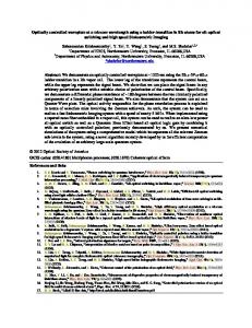
cation operations with specially selected operand values. This particular set of threads has been shown to maximise the power dissipation of the core [KE15]. After a warm-up period of one second, the values of the counters connected to the ROs are recorded, then the counters enabled, incrementing at a rate governed by the RO frequency. In testing, one second was found to be sufficient heating time to produce the observable RO slowdown. After 85 µS, the counters are stopped, re-read and the difference calculated. This measurement duration captures a good sample of the RO frequency, without overrunning the 16-bit counters. This measurement step can be performed several times to establish an average. The thread responsible for configuration and sampling of the ROs is inactive the majority of the time, leaving the warm-up threads to fully occupy the pipeline. Once sufficient samples are collected, the slowest of the device’s ROs is then taken as an approximation of the silicon speed. Two RO scaling characteristics, Sf and Sv , must be determined, with the aim of providing an analog for Equation 3, to give a target operating voltage and/or frequency (equivalent to determining appropriate Fnorm and Vnorm ). Sf is the ratio between RO frequency, Fo , and processor frequency, Fp , such that Fo indicates that the silicon is operating quickly enough to meet the timing requirements of the processor at Fp . This yields the inequality in Equation 5, which states the minimum Fo for a given target processor frequency. The second characteristic, Sv , is the ratio between core voltage and Fo , satisfying Equation 6.
XS1 processor – up to 8 threads Time
T0
T1
T2
T3
T4
T5+
Multiply loop (odd)
Unused threads
Boot Request tuning Start warm-up code
Fork warm-up threads
Wait for warm-up Start RO count Wait Stop & sample
... Start RO count Wait Stop & sample Signal warm-up end
Multiply loop (even)
Multiply loop (odd)
Multiply loop (even)
Join warm-up threads
Calculate & apply target voltage Continue executing application code
Figure 2: Depiction of voltage tuning process, including warm-up and RO sampling, followed by normal application execution. The framework is implemented as a series of libraries that provide control over the core voltage, routines for heating up the processor and a process for measuring the silicon speed and selecting an appropriate voltage for the given frequency. The implementation is outlined in Figure 2 and an explanation follows. The simplest invocation of the framework is to request that it set the core voltage to the lowest safe level for the given clock speed. When doing this, the framework first determines the frequency by reading the PLL configuration and core clock divider in combination with a compile time macro that specifies the oscillator frequency. This assumes, therefore, that the oscillator frequency is correctly specified by the hardware designer and/or software developer. Next, the processor is heated for a period of time which at its 65 nm feature size, will slow the ROs [KK06]. This aims to reflect the silicon speed under a heavy workload. This is achieved by executing several threads of interleaved multipli-
Fo ≥
Fp Sf
V ≥ Fo · Sv
(5) (6)
If Fo is the current RO frequency and V is the current core voltage, then a new target RO frequency, Fo0 , may be found that still satisfies Equation 5 and similarly a new voltage, V 0 , that can provide Fo0 , per Equation 6. In the above example it is assumed that the processor is operating safely and that a voltage optimisation is taking place. It is also possible to calculate a higher V 0 for a higher target processor
7
frequency, Fp0 , using the same method. In either case, V 0 is calculated using Equation 7. V 0 = V + Sv · Fo0 − Fo
�
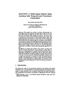
reading the power supply voltages, was used in order to accurately observe the changes in voltage that were applied. For each test run, the tuning process was performed and the target voltage set as per the description in Section 3. To verify system stability at the tuned voltage, a stress-test application is used, as described in Section 3.4. Prior to a full suite of tests, the Sf and Sv parameters were tested on slow silicon to confirm the parameters were chosen correctly to avoid failures or crashes on all samples of the chip. The tuning framework and stress-test is run three times on each of the nine processors and average values collected. It is worth noting, however, that there was negligible variation between test runs on any given sample processor. Tests were conducted at 500 MHz and 400 MHz to demonstrate the capability to tune depending on the required system performance. Figure 3 shows a box-plot of the reduction in static and dynamic processor power for each of the sampled chips at 500 MHz and 400 MHz, compared to the nominal operating voltage of 1 Volt. There is no voltage/frequency table specific for this processor, so this is the typical operating point, per the datasheet. The change in static and dynamic power is determined by evaluating the voltage terms in Equations 1 and 2, whilst the other terms remain unchanged. The figure also shows the kernel density plot of the data beneath the box-plots, forming a violin plot and projecting the behaviour for a larger sample set. At 500 MHz, the slowest processor of the sample set benefits from a 70 mV reduction in the core supply, yielding a dynamic power reduction to 0.86 of the default and a static power reduction to 0.92 of its original state. The fastest processor gets a 140 mV reduction, lowering dynamic power and static power to 0.75 and 0.87 of their prior levels, respectively. At 400 MHz, the power savings are greater and the distributions more spread out, but follows the same shape as for 500 MHz, in line with the characteristics of the sampled chips. Figure 4 projects the Fp0 and V 0 combinations across a wider range, demonstrating the range voltages that would be applied to different chip samples for a particular Fp0 . This data demonstrates that RO tuning can save system energy in all cases, but most importantly, can save more energy in processors where
(7)
The framework’s interface to the power supply can then perform the transition to V 0 within a safe slew rate, after which the tuning process is complete and the application can start. This process is constrained within maximum and minimum supported voltages and frequencies, based upon the power supply capabilities, recommended limits and the operating ranges that were used in order to generate safe values for Sf and Sv .
3.4 Characterisation Prior to testing this implementation, the RO characteristics Sf and Sv are determined through empirical measurement of an XMOS XS1-U8A-64 processor, shown in Table 1. The RO frequency in relation to voltage, Sv , is recorded, along with a conservative Sf , the result of a series of frequency and voltage tests in which a stress-test application was run to verify correct operation of the hardware at each frequency/voltage combination. The stress-test exercises multiple components of the processor simultaneously. It has three possible outcomes: success, where the test completes without error; failure, where an error is detected during execution; or crash, where the system becomes unresponsive. The test is not considered a certification of reliability (it comes with no guarantee from the vendor), but is sufficient for experimental purposes; if this test does not exhibit transient faults, none are seen in regular applications on the same test bed. Term Sf Sv
Value 1.7 5.95e − 06
Table 1: The RO scaling terms for a XS1-U8A-64 processor.
4 Testing Following the implementation of the voltage tuning framework, it was tested on nine XS1-U8A-64 processors, covering three each of slow, typical and fast silicon samples. A test rig, capable of
8
Relative change in power with tuning applied
Power savings with RO voltage tuning
for suitable samples of silicon and achieve power saving in all samples. The actual power saving will depend on the behaviour of the application, but in a typical scenario this may reduce the power dissipation from approximately 150 mW to 110 mW, when considering the power profile of the XS1-U8A-64. A conservative and linear relationship between RO frequency, target core frequency and lowest safe voltage is used. As such, the energy saving at a given frequency is not the absolute minimum, nor does the energy saving exactly fit the curve of the silicon’s performance as voltage and temperature change. Specifically targeted hardware solutions are therefore able to better characterise the critical path and provide tighter voltage tuning. However, this approach is still able to provide reliable operation whilst saving energy, provided there are no severe variations in the operating conditions. The strength of this approach is in its use of general purpose hardware for characterisation and software for control. This creates a highly flexible voltage tuning implementation that can be easily mapped to other similarly equipped devices, doesn’t interfere with the real-time behaviour of the running application, and is unconstrained in voltage/frequency selection except for any limitations imposed by the hardware.
1.00 0.95 0.90 0.85 0.80 0.75 0.70 0.65 0.60 0.55 500MHz Static 400MHz Static 500MHz Dynamic 400MHz Dynamic Frequency and power dissipation type
Figure 3: Violin plot of static and dynamic power savings for RO voltage tuning at 500 and 400 MHz across a sample of nine XS1-U8A-64 chips. The top whiskers represent the saving in the slowest silicon under test and the bottom whiskers represent the fastest sample. the silicon is fast enough to allow it. The achieved dynamic power saving across the sampled chips varies by 14% at the maximum operating frequency of 500 MHz, passing the critical path test application in all cases.
5 Evaluation
Core voltage (V)
Our RO based voltage tuning has been shown to be effective at reducing device energy consumption with zero impact on program performance, save for a slower start-up time. The method is able to save over 25% of power in the core supply 1.00 0.95 0.90 0.85 0.80 0.75 0.70 0.65 0.60
6 Future work Areas of future work include more sophisticated software implementations for the control loop, integration with different hardware critical path estimation methods, and the application of this work to other architectures. This section discusses all of these areas in turn.
Safe voltage/frequency range projection Upper bound (slowest silicon) Lower bound (fastest silicon)
100.0
200.0
300.0 400.0 500.0 Core clock frequency (MHz)
Software DVFS The current software implementation is run before program startup, minimising integration effort and guaranteeing no disruption to program execution. There is scope for applying this technique in a periodic manner, continuing to sample RO speed throughout program execution in order to adapt to environmental changes, or changes in the workload of the processor that might create more or less heat. On the current target architecture, this could be implemented as a dedicated
600.0
Figure 4: Projection of safe voltage/frequency combinations within 0.6–1.0 V for the fastest and slowest silicon samples tested.
9
thread, provided the instrumented application’s resource requirements (with respect to number of threads and performance) would not be adversely affected. This would allow our approach to be used as a continuous controller, in a comparable manner to full hardware implementations such as [BPSB00, DRL06, LS10]. In some applications, it may be beneficial to apply the constraints in reverse. For example, in an energy-scarce environment, a maximum voltage may be available, and so the control loop should tune frequency appropriately, maximising performance with the available voltage supply. This is a relatively straightforward task in terms of engineering the control framework, although the impact upon the performance of relevant applications would need to be studied.
variation across samples of a device and environmental factors such as temperature. This characterisation is utilised by a software control loop, which tunes the operating voltage of the device to a safe minimum at the required core clock frequency. The result is a variation sensitive power optimisation method that uses a simple hardware block and flexible software controller that can provide significant power savings. The characterisation and control method is demonstrated on a device with software accessible ring oscillators, the XMOS XS1-U8A-64 embedded microprocessor. In testing on a sample set of this processor, the method saves between 14% and 25% of dynamic power, demonstrating sensitivity to silicon speed and saving power in all test cases. The control method has zero impact on the performance of any application run on the processor as the optimisation is performed at start-up. The software implementation of this control method is available upon request to the authors. Further work has been proposed that would allow testing of this technique with other devices to allow closer comparison with other voltage tuning methods. In addition, the flexibility of the software control implementation could be leveraged to provide similar voltage tuning optimisations using other types of characterisation hardware or as a continuously operating control loop.
Critical path characterisation One of the key contributions of this paper is the use of a software controlled multi-purpose hardware block, rather than a dedicated hardware block designed for critical path representation. However, the software control loop could be integrated with an appropriately instrumented critical path representation such as the UDL [INS+ 12], creating a more accurate control loop that is still software driven. In addition, techniques similar to monitor timing slack such as that in [HH11] could be applied, although sufficiently fine grained and accurate voltage samples may be impractical in a hardwaresoftware control loop.
Acknowledgments The authors would like to thank Henk Muller and Jon Ferguson at XMOS for the supply of hardware enabling this research.
Other devices, direct comparison Wider comparisons could be drawn by applying this technique to a range of architectures, starting by identifying those with similarly controllable RO hardware. Of particular interest is FPGAs, with which work such as [NNY12, NY13] could be directly compared to our method, by instrumenting a design with each of the forms of sensing and control.
References [ANDS06] Kanak Agarwal, Kevin Nowka, Harmander Deogun, and Dennis Sylvester. Power Gating with Multiple Sleep Modes. In 7th International Symposium on Quality Electronic Design (ISQED’06), pages 633–637. IEEE, 2006. URL: http://ieeexplore. ieee.org/lpdocs/epic03/ wrapper.htm?arnumber=1613208, doi:10.1109/ISQED.2006.102.
7 Conclusions This paper has presented a technique for using multi-purpose ring oscillators to provide a characterisation of device speed, accounting for process
10
[ANG08]
[BG13]
H Amur, Ripal Nathuji, and M Ghosh. IdlePower: Application-aware management of processor idle states. Proceedings of MMCS, 2008. URL: http: //www.cc.gatech.edu/grads/h/ hamur3/mmcs08_angsl.pdf.
org/lpdocs/epic03/wrapper. doi: htm?arnumber=5460977, 10.1109/TVLSI.2010.2048587. [INS+ 12]
Dominik Brodowski and Nico Golde. CPU frequency and voltage scaling code in the Linux kernel, 2013. URL: https://www.kernel.org/ doc/Documentation/cpu-freq/ governors.txt.
[BPSB00] TD Burd, TA Pering, A.J. Stratakos, and R.W. Brodersen. A dynamic voltage scaled microprocessor system. IEEE Journal of Solid-State Circuits, 35(11):1571–1580, November 2000. URL: http://ieeexplore.ieee. org/xpls/abs_all.jsp?arnumber= 881202http://ieeexplore. ieee.org/lpdocs/epic03/ wrapper.htm?arnumber=881202, doi:10.1109/4.881202. [BTM00]
[KABM03] NS Kim, T Austin, D Baauw, and T Mudge. Leakage current: Moore’s law meets static power. Computer, pages 68–75, 2003. URL: http: //ieeexplore.ieee.org/xpls/ abs_all.jsp?arnumber=1250885.
David Brooks, Vivek Tiwari, and Margaret Martonosi. Wattch: A Framework for Architectural-Level Power Analysis and Optimizations. ACM SIGARCH Computer Architecture News, 28(2):83–94, May 2000. URL: http://portal.acm.org/ citation.cfm?id=339657http: //portal.acm.org/citation. cfm?doid=342001.339657, doi:10.1145/342001.339657.
[DRL06]
Shidhartha Das, David Roberts, and Seokwoo Lee. A self-tuning DVS processor using delay-error detection and correction. Solid-State Circuits, 41(4):792–804, 2006. URL: http: //ieeexplore.ieee.org/xpls/ abs_all.jsp?arnumber=1610623.
[HH11]
Wei-Chih Hsieh and Wei Hwang. Adaptive Power Control Technique on Power-Gated Circuitries. IEEE Transactions on Very Large Scale Integration (VLSI) Systems, 19(7):1167–1180, July 2011. URL: http://ieeexplore.ieee.
Yoshifumi Ikenaga, Masahiro Nomura, Shuji Suenaga, Hideo Sonohara, Yoshitaka Horikoshi, Toshiyuki Saito, Yukio Ohdaira, Yoichiro Nishio, Tomohiro Iwashita, Miyuki Satou, Koji Nishida, Koichi Nose, Koichiro Noguchi, Yoshihiro Hayashi, and Masayuki Mizuno. A 27% Active-Power-Reduced 40-nm CMOS Multimedia SoC With Adaptive Voltage Scaling Using Distributed Universal Delay Lines. IEEE Journal of SolidState Circuits, 47(4):832–840, April 2012. URL: http://ieeexplore. ieee.org/lpdocs/epic03/ wrapper.htm?arnumber=6151871, doi:10.1109/JSSC.2012.2185340.
11
[KE15]
Steve Kerrison and Kerstin Eder. Energy modelling of software for a hardware multi-threaded embedded microprocessor. Transactions on Embedded Computer Systems (TECS), page 5, 2015.
[KK06]
Ranjith Kumar and Volkan Kursun. Reversed temperature-dependent propagation delay characteristics in nanometer CMOS circuits. IEEE Transactions on Circuits and Systems II: Express Briefs, 53(10):1078–1082, 2006. doi:10.1109/TCSII.2006.882218.
[LS00]
Seongsoo Lee and Takayasu Sakurai. Run-time voltage hopping for low-power real-time systems. Proceedings of the 37th conference on Design automation - DAC ’00, (c):806–809, 2000. URL: http://portal.acm.org/citation.
ternational Conference on, pages 74– 77, 1988. doi:10.1109/ICCAD.1988. 122466.
cfm?doid=337292.337785, doi:10.1145/337292.337785. [LS10]
[May09]
Qunzeng Liu and Sachin S Sapatnekar. Capturing Post-Silicon Variations Using a Representative Critical Path. IEEE Transactions on Computer-Aided Design of Integrated Circuits and Systems, 29(2):211–222, February 2010. URL: http://ieeexplore. ieee.org/lpdocs/epic03/ wrapper.htm?arnumber=5395738, doi:10.1109/TCAD.2009.2035552.
[SPKG10] John Sartori, Aashish Pant, Rakesh Kumar, and Puneet Gupta. Variationaware speed binning of multi-core processors. In 2010 11th International Symposium on Quality Electronic Design (ISQED), pages 307–314. IEEE, March 2010. URL: http://ieeexplore.ieee. org/lpdocs/epic03/wrapper. htm?arnumber=5450442, doi: 10.1109/ISQED.2010.5450442.
David May. XMOS XS1 Instruction Set Architecture, 2009.
[WA12]
David Wolpert and Paul Ampadu. Managing Temperature Effects in Nanoscale Adaptive Systems. Number 0. Springer New York, New York, NY, 2012. URL: http: //link.springer.com/chapter/10. 1007/978-1-4614-0748-5_2http: //link.springer.com/10. 1007/978-1-4614-0748-5, doi:10.1007/978-1-4614-0748-5.
[WKG94]
TC Weigandt, Beomsup Kim, and PR Gray. Analysis of timing jitter in CMOS ring oscillators. Circuits and Systems, pages 27–30, 1994. URL: http: //ieeexplore.ieee.org/xpls/ abs_all.jsp?arnumber=409188.
[MDO+ 08] David May, Ali Dixon, Ayewin Oung, Henk Muller, and Mark Lippett. XS1L System Specification, 2008. [MS10]
[NNY12]
[NY13]
[Sak88]
MK Mandal and BC Sarkar. Ring oscillators: Characteristics and applications. Indian Journal of Pure and Applied Physics, 48(February):136–145, 2010. URL: http://www.tjdb.org/123456789/ 7244/1/IJPAP48(2)136-145.pdf. Atukem Nabina and Jose Luis Nunez-Yanez. Adaptive Voltage Scaling in a Dynamically Reconfigurable FPGA-Based Platform. ACM Transactions on Reconfigurable Technology and Systems, 5(4):1–22, December 2012. URL: http://dl.acm.org/citation. cfm?doid=2392616.2392618, doi:10.1145/2392616.2392618.
[WWA01] G. D. Wilk, R. M. Wallace, and J. M. Anthony. High-κ gate dielectrics: Current status and materials properties considerations. Journal of Applied Physics, 89(10):5243, 2001. URL: http://scitation. aip.org/content/aip/journal/ jap/89/10/10.1063/1.1361065, doi:10.1063/1.1361065.
Jose Luis Nunez-Yanez. Adaptive Voltage Scaling with in-situ Detectors in Commercial FPGAs. IEEE Transactions on Computers, 2013. doi: http://doi.ieeecomputersociety. org/10.1109/TC.2013.73.
[XMO10]
T Sakurai. CMOS inverter delay and other formulas using alpha power law MOS model. In ComputerAided Design, 1988. ICCAD-88. Digest of Technical Papers., IEEE In-
12
XMOS. Random numbers on the XS1L1. Technical report, 2010.