Tuning of a PID controller Using a Multi-objective Optimization Technique Applied to A Neutralization Plant Andrey Popov, Adel Farag and Herbert Werner Hamburg University of Technology, Institute of Control Engineering
[email protected], adel
[email protected],
[email protected]
Abstract— Most control engineering problems are characterized by several, often contradicting, objectives, which have to be satisfied simultaneously. Two widely used methods for finding the optimal solution to such problems are aggregating to a single criterion, and using Pareto-optimal solutions. Here we propose a Genetic Algorithm (GA) approach using a combination of both methods to find a fixed-gain, discrete-time PID controller for a chemical neutralization plant. Known to be highly non-linear and with varying time delay, this plant provides a challenging testbed for nonlinear control strategies. Experimental results confirm that a multi-objective, Pareto-based GA search gives a better performance than a single objective GA. The former method was also used to design a gain-scheduled PID controller, for which also experimental results are shown.
I. INTRODUCTION Most control engineering problems are characterized by several objectives that must be satisfied. Engineers are often faced with design problems, where a controller is needed that provides e.g. a fast response, small overshoot, no oscillation and economical control. There are mainly two ways of tackling this problem: (i) aggregating the objectives to a single objective or (ii) solving a multi-objective optimization problem (Pareto-based method). Aggregating several objectives into a single objective has the advantage of solving a simpler problem, but on the other hand many design iterations are required to obtain an acceptable compromise. On the other hand, the multi-objective approach is claimed to lead to a set of solutions each of which dominates the others in some sense. This paper compares these two techniques by applying them to a practical controller design problem: to design a gain-scheduled PID controller for a chemical titration and neutralization plant (TINA). This plant is known to be highly nonlinear, which makes it suitable for comparison. In [1], [2] and [4] different solutions to this problem are proposed. Here, however we consider the design of a standard PID controller. This controller type is still the one most widely used in industry [5]. The ease of manual fine-tuning of the three coefficients makes PID controllers the preferred choice for many processes. Here we consider a disturbance rejection problem and the design of both a fixed-coefficient and a gainscheduled discrete-time PID controller. Although a variety of PID tuning techniques is available [5], the most efficient way to tune the parameters of a PID controller for non-linear or high-order systems is direct optimization. This requires however the solution of non-
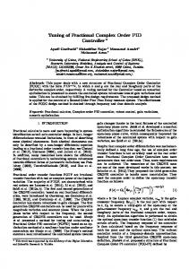
convex problems. Genetic algorithms (GA) are well suited for a variety of optimization problems in the control field [3]. The single-objective approach is implemented using the GA and direct search toolbox for Matlab 7.0. The multi-objective algorithm used here is the Strength Pareto Evolutionary Algorithm (SPEA2) [8], [7], which is one of the most powerful multi-objective techniques, and has outperformed many other algorithms (e.g. the one proposed in [6]). II. T ITRATION AND N EUTRALIZATION P LANT A laboratory scale chemical plant, allowing titration and neutralization of chemical substances, is available at the TUHH Institute of Control Engineering and was used to neutralize hydrochloric acid (HCl) and Natrium Hydroxide (N a OH). Fig. 1 shows a diagram of the reaction tank. The acid inflow is controlled by a pump, and the base inflow by a valve. The pH value of the acid is 1.7 ± 0.05 and the pH of the base is 12.5 ± 0.1. Separate loops are controlling the liquid level and the temperature in the reaction tank to keep it at 210 ± 10 mm and 21 ± 1 ◦ C, respectively. Those lowlevel loops and the mixer in the tank operate independently and are not considered here. acid
base
HCl
NaOH
pH
Fig. 1.
Reaction tank
The neutralization plant is characterized by strongly nonlinear behaviour, having operating points with very high gain and operating points with very low gain, as well as saturation and time variations caused by buffering species (salt, contaminations, etc). An additional difficulty is due to the significant longer time delay of the base actuator (valve) than that of the acid actuator (pump). Two titration curves (one showing transition from acid to base and one the opposite direction) are shown in Fig. 2. Depending on its sign, the control signal is applied either to the valve (positive values of the control signal) or the
Titration curves 12
Disturbance signal normalized units
Base inflow 0.83 ml/s Acid inflow 3 ml/s
pH
10
8
0.2 0 −0.2
6 0 4
0
50
100
150
Fig. 2.
200 Time [s]
250
300
350
500
1000 time [s]
1500
2000
400
Fig. 4.
Titration curves
Applied disturbance signal
Comparison with P controller and K = 0.015 p
12 TINA output NN output
11
pump. Both have non-linear characteristics, shown in Fig. 3. As a first step, the dead-zone of the actuators was compensated for by adding an offset, and the characteristics were linearized around 0 by increasing the gain for the base signal.
10 9
pH
8 Actuator characteristics 100
7 Valve Pump
6
output flow [ml/s]
80
5 60 4 40
3
0
500
1000 time [s]
1500
2000
20
0
Fig. 5. 0
0.2 0.4 0.6 0.8 input for valve and pump (normalized signal [0 1])
Fig. 3.
Model validation
1
Actuator characteristics
III. PROBLEM FORMULATION A stabilization and disturbance rejection task is considered. The pH value in the reaction tank should be kept constant at 7 and disturbances applied to the input of the plant should be rejected. Experimental data from the plant running in closed-loop operation with varying disturbance signals (Fig. 4) have been gathered. During the experiment a proportional controller was used to keep the pH value around 7 and avoid saturation. The same disturbance signal was used again later in the tuning process. The data set was then used to train a neural network (NN). Using the NN identification toolbox ([9]), a satisfactory model of the plant was obtained. Comparison of the model output with a cross-validation data set is shown in Fig. 5. One can clearly see that step disturbances of same amplitude but opposite directions (acid and base) have different effects. For large disturbance amplitudes the compensation of acid takes about twice the time as that for base. IV. FIXED GAIN PID CONTROL Two design objectives are considered: (1) minimal error (e) between the reference signal and the output and (2) minimal control (u). Whereas minimizing the first objective will provide good reference tracking and better disturbance
rejection, minimizing the second reduces the quantity of of acid and base and thus the cost of the control. The mathematical description of these objectives are given below Z Ts J1 = e2 (t)dt (1) 0
Z J2 =
Ts
|u(t)|dt
(2)
0
where Ts = 2000s is the simulation time. The first objective is the integral squared error, so large amplitudes are penalized. On the other hand, J2 is a good measure of the total acid and base quantities required for control. Using the NN non-linear model and J2 as the integral of the absolute error makes the optimization problem non-convex. Here we will use only these two objectives, the Pareto-surface of which can be easily displayed. However, more objectives (e.g. separate measures for acid and base) can be introduced if necessary. First we use the objective aggregation method and combine the two objectives into a single one. Then we compare the results with those obtained by multi-objective optimization. In both cases we have three design parameters: KP , KI and KD of the PID controller. The sampling time is Ts = 0.5s. The transfer function of the PID controller is 2z−2 KTs +KD K(z) =KP +KI z−1 (Ts +2Tc )z +Ts −2Tc where Tc = 0.5ms is the time constant for the derivative.
Pareto−surface obtained with single−objective optimization
A. Objective Aggregation
120
When using objective aggregation, weight factors are introduced that give different priority to different objectives. Here we need only one weight W to aggregate J1 and J2 to
Log scale 10−1:102 Scale 0.1:0.1:1 Scale 1:1:10 Scale 10:10:100 Scale 50:1:70
110 100
Objective values J
80 70 60 50 40 30 20 5000
6000
Fig. 6.
7000 8000 Objective values J1
9000
10000
Single-objective optimization results
The algorithm selected here is SPEA [7], [8]. The available C code, PISA format ([13]) version of the algorithm, was modified to allow system simulation and calculation of the objective functions in a MATLAB environment. Here again fragment-exponential encoding of the PID coefficients was used. Population size and Pareto-set size of 50 points were found to give a good distribution over the Pareto-surface. At the same time 200 generations are enough for the algorithm to converge to a set close to the expected optimal one. The resulting Pareto-surface is shown in Fig. 7. Pareto−optimal set obtained with SPEA 120
100
2
Before starting the optimization, one needs to specify a value for W . At this stage factors like the ”raw” values of the objective functions and their importance could be considered when choosing the appropriate weight. When, however, such information is not available, different values of W are used and the corresponding system behaviors are compared. A population size of 20 individuals for the GA is chosen. Fragment-exponential encoding of the PID coefficients is used, by which each coefficient is encoded by two design variables using the form K = p1 10p2 . This allows the GA to search a wide range of values, with a small change of the exponential variable. Preliminary optimization runs show that 200 generations are sufficient from the point of view of convergence and repeatability of the results. Simulations for 52 different weights were performed. With the obtained PID coefficients the separate values of J1 and J2 were computed and the results are shown in Fig. 6. Seven dominated points, which are above and to the right of the plot area, are not shown. At first a logarithmic scale for the weight was used from 10−1 to 102 and 7 points were found. It is important to note that the computation time for each weight value is approximately 45 min on a 2.6 GHz Pentium IV processor. The results were used to define the precise search area: from 0.1 with step size 0.1 to 1; from 1 with step size 1 to 10 and from there with step size 10 up to 100. The resulting points on the Pareto surface were still clustered in two areas, and the edge elements were found to be 50 and 70. A step size of 1 was used to scan the area between them, but the corresponding results were still on either side of the gap. Significantly increasing the population size (500) did not help finding points in the gap. Due to the long computation time this approach was not pursued further. The main reason for the gap existing in Fig. 6 is the high sensitivity of the aggregated objective function (J1 + W J2 ) at some regions of the Pareto-set to changes in the tuning parameter W . For example a very small change of the weight between 56 and 61 gives a huge change of the trade-off between J1 and J2 . The elements in-between were converging either to one of the sides or to a dominated point far from the surface.
Objective values J
(3)
2
90
Ja = J1 + W J2
80
60
40
20
0 4000
5000
6000
7000
8000 9000 10000 11000 12000 13000 Objective values J 1
Fig. 7.
Multi-objective optimization results
B. Multi-Objective GA (MOGA) In contrast to the single-objective algorithms, which try to find a single solution of the problem, the multi-objective technique searches for the optimal Pareto set directly. A solution is said to be Pareto-optimal (non-dominated), if there exists no other solution which simultaneously improves the values of both objectives (J1 and J2 ). GA are particulary well suited for multi-objective techniques, because they work with a population of solutions rather than a single solution.
C. Simulation and Experimental Results In Fig. 8 the results obtained with the two methods are shown together. In [7] a method for comparing results from multi-objective optimizations is proposed, but since it involves knowledge of the Pareto-optimal surface we cannot apply it here. It is important to note that to obtain the 52 points with the aggregation method, a total number of 52 × 200 × 20 = 208000 closed-loop simulations had
Output pH for−6 point 2 −17 KP = 1.56 10−2; KI = 9.97 10 ; KD = 5.39 10 ≈ 0 12
pH
10 8 6 4 0
500
0.1 control units
to be performed, while for the 50 points on the multiobjective method only 50 × 200 = 10000 simulations were needed. This means that MOGA is 20 times faster than the aggregation technique. Furthermore, the aggregation method was not able to find all points of the Pareto optimal set. Three of the solutions, numbered from 1 to 3 in Fig. 8 were chosen and experiments on TINA were performed with the corresponding controllers. Points number 1 and 3, were chosen to match both the results from single-objective and multiobjective optimization. The simulation and experimental results are compared in Fig. 9 to 11.
1000 time [s] Applied control signal
1500
2000
1000 time [s]
1500
2000
Experiemental Simulation
0.05 0 −0.05
Pareto−surface obtained with single− and multiobjective optimization −0.1
120 Single Objective Multiobjective Selected results
100
0
500
1
Fig. 10.
Simulation and experimental results for point 2
Objective values J2
80 Output pH for point 3 −3 −12 −11 KP = 5.74 10 ; KI = 9.75 10 ; KD = 1.91 10
2
60
12 10 pH
40
8 6
3 20
4 0
0 5000
6000
7000
8000 9000 10000 Objective values J
11000
500
12000 0.1
Fig. 8. Single and multi-objective optimization Pareto-sets and chosen points for experiments
control units
1
1000 time [s] Applied control signal
1500
2000
1000 time [s]
1500
2000
Experiemental Simulation
0.05 0 −0.05 −0.1 0
Output pH for point 1 −2 −12 −3 KP = 2.77 10 ; KI = 9.20 10 ; KD = 2.40 10
500
12
Fig. 11.
pH
10
Simulation and experimental results for point 3
8 6
V. GAIN-SCHEDULED PID CONTROL
4 0
control units
0.1
500
1000 time [s] Applied control signal
1500
2000
1000 time [s]
1500
2000
Experiemental Simulation
0.05 0 −0.05 −0.1 0
Fig. 9.
500
Simulation and experimental results for point 1
As shown in the figures the integral gain of the PID controller is relatively small, because the plant itself has integral action: even a small input, applied to the plant for a long time, can drive it into saturation zones. The derivative gains are small, due to the oscillatory behavior introduced by modelling errors.
Having shown that multiobjective GA optimization delivers better results than the single-objective optimization for the given design problem, we will use the former to find a gain-scheduled PID controller for the titration and neutralization plant. The objective functions remain the same as in (1) and (2). The gain-scheduled control law is of the form KP (k) = KP 0 + KP 1 ε(k) + KP 2 ε2 (k)
(4)
where ε(k) = pH(k) − CpH . Thus we have a total of 6 design parameters: KP 0 , KP 1 , KP 2 , CpH and KI and KD . Running SPEA with the same parameters (population size of 50 and 200 generations) we obtain a new Pareto-surface, which is shown in Fig. 12 together with the one obtained via a fixed-gain PID controller. From the obtained points we select one (number 4 in Fig. 12) with coefficients
Gain−scheduled and fixed−gain Pareto surfaces
VI. CONCLUSIONS AND FUTURE WORKS
120 Fixed coefficients PID Selected fixed. coef. PID Gain−scheduled PID Selected gain−scheduled PID
100
Objective values J2
80
60
40
4
R EFERENCES
5 20
0 2000
Fig. 12.
4000
6000 8000 10000 Objective values J1
12000
Comparison between fixed-gain and gain-scheduled controllers
KP 0 = 5.26 · 10−4 ; KP 1 = −2.52 · 10−3 ; KP 2 = 1.25 · 10−3 ; CpH = 8.68; KI = 2.28 · 10−8 ; KD = 2.62 · 10−4 . To demonstrate the performance improvement achieved by gain-scheduling, the responses achieved with controllers corresponding to points 3 and 4 are compared in Fig. 13.
Output pH for points 3 and 5 12
pH
10 8 6 4 0
0.1 control units
Two GA search techniques - aggregation into a single objective and using Pareto-optimal solutions (MOGA) - have been used to design a fixed-gain PID controller for a highly nonlinear chemical pilot plant. Experimental results confirm that MOGA is superior in terms of efficiency. This latter approach has also been used to design a gain-scheduled PID controller for this plant, which has been successfully tested experimentally.
500
1000 time [s] Applied control signal
1500
2000
1000 time [s]
1500
2000
Fixed gain Gain scheduled
0.05 0 −0.05 −0.1 0
500
Fig. 13. Comparison of the response with fixed-gain and gain-scheduled PID control for the same value of J2
From the results it is obvious that the gain-scheduled PID controller shows most of the time a faster disturbance rejection than the fixed-gain PID controller. For the last three disturbance impulses the response is almost two times faster with the gain scheduled controller. The only exception is the third group of disturbance impulses (600 to 900 s), where the fixed-gain PID controller shows better performance. The better performance of the gain-scheduled controller in rejecting acid disturbances is due to the larger control signal (larger amplitude for a short period of time).
[1] M. Mwembeshi, C. Kent and S Salhi, ”Flexible on-line Modeling and Control of pH in waste neutralisation reactors”, Chemical Engineering & Technology Journal, 27 (2), (2004), pp. 130-138. [2] M. Mwembeshi, C. Kent and S Salhi, ”A GA Approach to Robust and Flexible Modelling and Control of PH in reactors”, Computers and Chemical Engineering, 28 (9), (2004), pp. 1743-1757. [3] A. Farag, H. Werner, M. Aten, Decentralised Control of a High Voltage DC System Using Genetic Algorithms, Proceeding of IFAC World Congress, Barcelona, Spain,2002. [4] D. Dougherty and D. Cooper, ”A Practical Multiple Model Adaptive Strategy for Multivariable Model Predictive Control”, Control Engineering Practice, 11 2003, pp. 649. ˚ om and T. H¨agglund, PID Controllers: Theory, Design and [5] K. Astr¨ Tunning, ISA-The Instrumentation, Systems and Automation Society, NC, 1995. [6] C. Fonseca and P. Fleming, ”Genetic algorithms for multiobjective optimization: Formulation, discussion and generalization”, Proceedings of the Fifth International Conference on Genetic Algorithms, 1993, pp. 416423. [7] E. Zitzler, K. Deb, and L. Thiele, ”Comparison of multiobjective evolutionary algorithms: Empirical results”, Evolutionary Computation, 8(2), 2000, pp. 173195. [8] E. Zitzler, M. Laumanns and L. Thiele, ”SPEA2: Improving the Strength Pareto Evolutionary Algorithm for Multiobjective Optimization”, Evolutionary Methods for Design, Optimisation and Control with Application to Industrial Problems, Proceedings of the EUROGEN2001 Conference, 2001, pp.95-100. [9] M. Nørgaard, (on-line) http://www.iau.dtu.dk/research/control/nnsysid.html [10] H. Pohlheim, ”Visualization of Evolutionary Algorithms - Set of Standard Techniques and Multidimensional Visualization”, Proceedings of the Genetic and Evolutionary Computation Conference, 1999, pp. 533540. [11] G. Agrawal, K. Lewis, K. Chugh, C.-H. Huang, S. Parashar and C. Bloebaum, ”Intuitive Multidimensional Visualization for MDO”, 10th AIAA/USAF/NASA/ISSMO Symposium on Multidisciplinary Analysis and Optimization, 2004. [12] I. Griffin, P. Schroder, A. Chipperfield, and P. Fleming, Multi-objective optimization approach to the ALSTOM gasifier problem, Proceedings of the Institution of Mechanical Engineers, 214(I), 2000, pp. 453-468. [13] S. Bleuler, M. Laumanns, L. Thiele, E. Zitzler, ”PISA - A Platform and Programming Language Independent Interface for Search Algorithms”, Conference on Evolutionary Multi-Criterion Optimization, 4/2003, pp 494-508.