A Software Development Process for COTS-Based Information System Infrastructure: Part 1 Greg Fox, TRW Systems Integration Group Karen Lantner, EDS Steven Marcom, TRW Information Services Division The Infrastructure Incremental Development Process fills two gaps within the realm of software development processes: It provides a programmatic, prototype-driven, but carefully controlled approach to commercial-off-the-shelf selection and integration, and it provides a process that specifically addresses development not of applications but of the infrastructure of a large distributed information system.
T
he level of abstraction at which the software developer works has changed markedly throughout the last 40 years. Early programmers used ones and zeros to control the electronic switches within computers. That technology was followed by procedural languages that, from the programmer’s view, removed much of the physical housekeeping associated with the specific design of the computer. In recent years, an even higher level of abstraction has appeared: the integration of prepackaged commercial-off-the-shelf (COTS) software into system designs. In addition, the domain of software development has become segmented into different layers. For example, application-level software development can be distinguished from infrastructure-level software development.
The Emerging Divide in System Functionality The value of layering in software architecture and implementation is an established concept. Key to the layering model is the idea that through use of defined interfaces between layers, the impact of changes in any given layer can be largely isolated from the other layers. The concept of a services layer and of specialized software in the system acting as service providers has continued to © 1997 IEEE. This material is adapted and reprinted, with permission, from a paper presented at the IEEE/SEI-sponsored Fifth International Symposium on Assessment of Software Tools and Technologies, Pittsburgh, Pa. held June 3-5,1997, pp. 133-142. Part 2, which will appear in the April 1998 issue of CROSSTALK, describes real-world applications of the IIDA model and examines the practical lessons learned and pitfalls encountered. 20 CROSSTALK The Journal of Defense Software Engineering
grow from the simple beginnings in the operating system to become a fundamental architectural concept in modern system design. As reuse and portability of software applications across different vendor hardware platforms become an increasingly important goal, a more sophisticated model of service layers and service providers has emerged. The open systems movement cites application portability across computing platforms as a major economic driver [1, 2]. The National Institute of Standards and Technology (NIST) Application Portability Profile (APP) [3] provides one convenient model to define system layers and services that support portability. This model, along with standards, helps achieve application portability by guiding designers who plan to code new information systems in their entirety and by guiding selection of available software computing components from those available in the marketplace. Modern information system design models separate the business-specific application software layer in a system from the technology-based infrastructure software layer. An illustration of this approach is the information engineering method of separating business system architecture from technical architecture, which contains the computing infrastructure [4]. This separation into software layers, which is less formally addressed in other design methods, recognizes that change and evolution in information systems are driven by two independent forces: change in business requirements and change in technology. Decoupling the impact of business rule change from change in technology de-
creases the total amount of system rework necessary to support system evolvability over time. This decoupling is effectively implemented by modeling the infrastructure software using the concept of services layers and service providers.
Views of Infrastructure There are two ways to look at the infrastructure. One view is the services view of infrastructure as seen by business application developers. It includes Human Computer Interface, Systems Management, Security, Work-Flow Management, Telecommunications, Data Interchange, Transaction Processing, Data Management, and Operating Systems. This grouping of infrastructure services was derived from the NIST APP. Infrastructure services are delivered to the applications through an application programming interface (API). The second view is the structural view, which includes the kinds of components infrastructure developers use to construct their view of the infrastructure: a set of connected software, network, and hardware components. These include developed software components, COTS software components, communications circuits, local area networks, special purpose servers, general purpose servers, workstations, and laptops. An additional set of functionalities, treated as part of the infrastructure during the development process, are the technical applications needed to operate the system. These applications neither implement business functionality nor provide services to the business application. They are, for example, the tools for system security administration, database
March 1998
A Software Development Process for COTS-Based Information System Infrastructure: Part 1
administration, system configuration control, software distribution, and, in general, the tool-set for enterprise-level systems management. Other infrastructure services are also used internal to the infrastructure but are not visible to business applications or end users. For example, a remote data access protocol is a level of service provided between infrastructure components that is used to construct a mechanism to access data: It is not directly visible to business applications or end users. Infrastructure services provide functionality that the application developer can access external to the application and, therefore, does not develop as part of the application. Economy of scale is achieved through common use of technical services by application development projects across the enterprise. Programmers can access infrastructure services without regard to how underlying infrastructure services have been implemented using a properly designed API. By allowing application and infrastructure development to be separate and independent, infrastructure enhancements, e.g., increased performance, additional services, and new computing platforms, can be made with minimal effects on application development.
The COTS Challenge for Infrastructure Although distributed systems (popularly described as client-server or networked systems) dominate today’s computer system design, they still have the character of adolescence. We are in the middle of a dramatic and somewhat uncontrolled expansion and evolution of standards for COTS software products for distributed systems. COTS products provide portions of needed supporting technical functionality to turn collections of computing platforms into unified, distributed computing environments. Available COTS software products offer varying degrees of standards compliance, interoperability, heterogeneous computing platform support, security functionality, performance efficiency, and distributed environment transparency for applications using their services. March 1998
Two separate panels at the 1995 Software Engineering Institute/Microelectronics and Computer Technology Corporation Symposium on “The Use of COTS in Systems Integration” concluded that “there is a need for process definitions for COTS usage,” [5] and “new lifecycle models for COTS integration projects are needed.” [6] Currently, documented software development lifecycle processes provide little practical guidance to developers to achieve the advantages of COTS software or to assist in the selection of specific products from the myriad available. COTS product selection and integration are complicated by an intrinsic set of special characteristics: incompatibility, inflexibility, complexity, and transience. Development Lifecycle Process Impact The special characteristics of COTS software integration change the emphasis in the classic waterfall lifecycle stages of planning, definition, analysis, design, construction, integration and test, implementation, deployment, and maintenance. COTS-based development differs from business application-oriented development in that the COTS selection process must occur early in the lifecycle. COTS evaluation and selection become a critical part of the early analysis process rather than a peripheral activity within the later design process. The challenges of COTS incompatibility, inflexibility, complexity, and transience must be addressed in the selection process because the infrastructure will ultimately consist of a suite of COTS products that must operate in harmony. In addition, since COTS software does not require coding but does require integration with other components, it starts the lifecycle as a partially developed component. The design, construction, and integration and test development stages must be recast to accommodate early COTS software integration and testing as well as to develop glue code: interface software, configuration files, scripts, utilities, and data files required to make the COTS software deliver its intended functionality. The proper development and
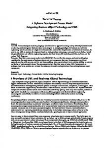
testing of the glue code to make a COTS package work may not be a trivial undertaking. For more complex COTS software, the development of glue code might need to be treated in the same manner as the development of a traditional custom-coded software module. When a COTS product enters the development process, the first task is to test and integrate it into the system. This activity starts early in the development process. Waiting until late in the development process to test and integrate COTS products, particularly those that are complex, will not give adequate time to master all their intricacies and complexities. COTS product testing and integration activities must be interwoven into more of the development process stages. COTS Incompatibility Many vendors do not develop their products along the lines of the layering models discussed earlier. As this is being written, no single commercially available software product or product family can provide all the infrastructure services needed for an enterprise-level information system of substantial size or complexity. The problem to be solved in system design and development is to select a compatible set of software products that can be integrated together and augmented by glue code to produce a complete set of services. In an ideal world, a set of products that provide all the needed infrastructure services would simply “snap together” like the pieces in the puzzle shown in Figure 1. In the real world, this is not the case: when put together, COTS pieces have gaps and overlaps. At any point in time, the set of services that a system designer can specify as useful exceeds what is available in mature products in the marketplace. The resulting gaps can be overcome in two ways. One is by traditional design and development of custom infrastructure software added around the commercially available products selected (either adding layers between the COTS-based infrastructure and the applications or adding custom service-provider software that is concepCROSSTALK The Journal of Defense Software Engineering 21
Software Engineering Technology
replace the software, work around the unexpected behavior, or change requirements. Understanding the behavior of an unmodifiable software component is a different process than specifying the behavior of a component to be constructed. Most documented software development methods take the latter approach and do not address the former.
Figure 1. Generic information system infrastructure service.
tually parallel to the COTS software). Another way is by leaving it to the application designers to deal with at the application level. Overlaps between products can cause a greater system design problem than gaps. Commercial software suppliers are driven much more by a desire to capture larger segments of the marketplace than they are by adherence to recommended system implementation layering models. For example, boundaries between database access, transaction processing, and work-flow management software products begin to overlap and blur as each vendor community expands its product’s features in pursuit of increased market share. This expansion in features is driven by requests for increased functionality by the installed base, not by the boundaries defined in layering models. The net result is that certain products and product sets do not work synergistically with other products; yet, none of the products on its own is complete enough to provide all of the necessary functionality. Selection of a specific product that provides a certain set of services often precludes selection of another functionally complementary product. COTS Inflexibility The inflexibility characteristic of COTS software can cause both design and integration difficulties. Unlike customdeveloped software, when a piece of commercial software exhibits a behavior not expected by the system designer, the developer cannot merely change the behavior of that software but must either 22 CROSSTALK The Journal of Defense Software Engineering
COTS Complexity The complexity characteristic of many of today’s advanced COTS software products causes distortions in the traditional development process time line. The flexibility and tailorability of product families like transaction monitors, workflow managers, and system management frameworks mean a significant education investment. The investment must be made upfront before the product can be fully evaluated for selection, and in cases when the product proves unsuitable, the investment might have a zero net return. Experience shows that the selection process for one major product can require three to six months of calendar time, multiple engineers and programmers, access to sophisticated suites of hardware and software environments, and will likely entail the purchase of vendor-provided training classes. The more complex COTS software products are tailorable and scalable to multiple hardware configurations, software environments, and workload environments. To achieve this flexibility, they contain from dozens to hundreds of adjustable parameters (or “knobs”). Each of these must be set for the specific system configuration. If the system is being built for deployment in multiple locations with different hardware configurations or workload environments, the COTS software parameters might need to be tuned for each installation. This can be a complex task requiring product expertise, experience with the behavior of the integrated system, and, potentially, support from analytic modeling efforts. Software configuration files for each location might need to be tailored using the information developed during system integration. Not only does this require additional development effort, the scheduling process must recognize
that just because the system has been integrated and tested in a test facility does not mean that it can be quickly made operational at a production location. The tailoring and tuning process for each location’s configuration can require days, weeks, or months. COTS Transience COTS software products are characterized by periodic updates. Updates might add functionality but are often incompatible with other system components. On the other hand, remaining with older versions of COTS products might cause future interoperability problems with upgrades to other COTS software. COTS software updates, particularly operating system updates, must always be evaluated for insertion into the system, since critical vendor maintenance and support for older versions often ceases. Management, cost, and technical factors in the transition to new COTS software versions can be formidable, particularly in a system with dozens of interrelated products upgraded by their vendors on different calendar cycles.
The Infrastructure Incremental Development Approach (IIDA) The development of a COTS-based technical infrastructure demands an approach that is fundamentally different from traditional approaches used for business-oriented applications: one that is heavily prototype-oriented, emphasizes testing, and evolves through multiple iterations. The IIDA is a tailored lifecycle that preserves the benefits of existing structured processes for software development while adapting to the particular characteristics of integrating COTS products. The IIDA is a combination of the classical waterfall development model [7] and the spiral development model [8], but the emphasis is on establishing compatibility and completeness rather than on component-level specifications. Overview of IIDA The IIDA is an iterative and incremental approach to infrastructure development where each version of the infrastructure is an increment that is integrated into March 1998
A Software Development Process for COTS-Based Information System Infrastructure: Part 1
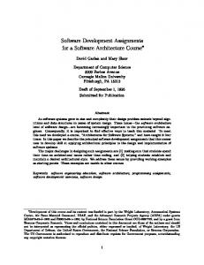
Figure 2. Infrastructure development approach.
the existing infrastructure baseline. Within each version, development proceeds in time-sequenced stages with iterative feedback to preceding stages (see Figure 2). The target infrastructure is the longterm vision for the infrastructure. It is defined and subsequently refined during the Definition and Analysis Stage through a top-down process of analysis of the enterprise requirements, enterprise adopted standards, and the system architecture. The Technical Strategies component captures the high-level description of the complete system vision and defines how the infrastructure will operate [9]. The Services Identification component is built up over time and is influenced by technology trends, product assessments, and the anticipated needs of the business applications. Development cycle stages are augmented with a series of structured prototypes for COTS product evaluation and integration. For each COTS family, the prototypes evolve from initial analysis prototypes for a make-or-buy decision to, first, a series of design prototypes for COTS product selection and detailed assessment, and next, to a demonstration prototype that becomes part of the development test bed. The timing of the prototypes aligns with the development stages, which depend on the products from their corresponding prototypes. This close coupling of prototyping and classic development stages characterizes the IIDA. Each pass through the stages in Figure 2 yields an incremental version March 1998
of the infrastructure that can be integrated with applications and deployed. After the implementation of each version, successive developmental cycles are initiated. The infrastructure thus evolves toward the target infrastructure by providing an increased level of services to business applications and developers and by incorporating new underlying technology and products. Infrastructure components are integrated into the existing infrastructure baseline. The components in this integrated infrastructure baseline are then ready to be integrated and tested with business applications. Infrastructure development ends with a technical platform upon which business applications can run effectively rather than with an operational product. The scope of this article is infrastructure development: It does not include the external integration, testing, or distribution of business applications. IIDA Stages The following is a summary of the major activities of each IIDA stage. Definition and Analysis Stage • Enterprise requirements and standards, system architecture, and technical strategies are defined and refined. • Version-specific functional infrastructure requirements are established by considering business application areas, architectural imperatives, and technology availability.
Functional Design Stage • Services included in the target and current versions are identified and defined. • Prototypes are used to identify leading candidate COTS components. Physical Design Stage • Interfaces between applications and infrastructure are defined (API is established). • Internal design of services is defined both functionally and technically. • COTS and to-be-built components are identified. • Prototypes are used to select and characterize COTS components. • Preliminary bill of materials is created for acquisition of equipment and COTS software products. • Design is calibrated for scaling and performance considerations to provide site designers with site configuration guidelines. • Structure of each to-be-built component and its interfaces is defined. Construction Stage • To-be-built components are constructed. • Glue code is developed, and the unit is tested. • COTS components, glue code, and built components are integrated into the infrastructure using the demonstration prototype as a test bed. Test Stage • Infrastructure versions are tested prior to being integrated and tested with business applications.
IIDA Milestones and Deliverable Documentation The infrastructure development approach uses formal and informal reviews, turnovers, and walk-throughs to maintain the degree of formality necessary to control and communicate the design (see Figure 3). Formal reviews include • Technical Review at the end of the Analysis Stage. • Design Review during the Physical Design Stage. • Test Review at end of the Test Stage. Formal reviews are attended by organizations external to the infrastructure development group as well as infrastructure developers and managers. CROSSTALK The Journal of Defense Software Engineering 23
Software Engineering Technology
These reviews occur once during the development cycle for each version of the infrastructure. Other reviews, turnovers, and walkthroughs are informal, rolling peer, or management reviews that typically occur when pieces of the design, construction, or integration are ready to be walked through. Infrastructure developers and managers participate in the following informal internal reviews. • Top-Level Design Walk-throughs during the Definition and Analysis Stage. • Design Turnovers (from design to development organization) during the Physical Design Stage. • Detailed Design Walk-throughs at the end of the Physical Design Stage. • Code Walk-throughs during the Construction Stage. • Test Design Walk-throughs during the Construction Stage. • Development Turnovers (from development to test organization) at the end of the Construction Stage. The lower portion of Figure 3 shows the key documents produced during the IIDA process. Target infrastructure documents, which include Enterprise Requirements, Technical Strategies, and Services Identification, are created once at the beginning of infrastructure development and updated as versions are produced. Version-specific infrastructure documents are created for each infrastructure version. Not shown in the tables are the informal documentation packages developed for the formal reviews and informal walk-throughs.
The Critical Role of Prototypes At the heart of the IIDA approach is a series of tailored prototypes, shown as Analysis, Design, Detailed Design, and Demonstration prototypes in Figure 2, which also illustrates their respective time phasing in the overall process. This can be viewed as a tailoring of the spiral development model as each successive set of prototypes narrows the solution space for the final implementation. Analysis Prototypes Analysis prototypes are used to identify leading candidate COTS software prod24 CROSSTALK The Journal of Defense Software Engineering
Figure 3. Infrastructure milestones and deliverable documents.
ucts in each COTS family. A COTS family is defined as a group of COTS software products that performs similar functions or provides related services to the application developers. Analysis prototypes are designed to exercise a COTS product to determine its general capabilities and to discover how well it satisfies the needs of the current version of the infrastructure. Selection of the best product in each family is performed later using the design prototypes. A sample application can be written to serve as a test vehicle for the family of products under evaluation because infrastructure, by its very nature, provides services rather than active applications. The results of the analysis prototypes feed the version-specific services definition and the version-specific services application programming interface (API) efforts with information on available COTS product behavior and performance. A suite of COTS products will be recommended as a result of these prototypes that, when combined with custom-developed glue code and to-bebuilt software, cover all the requirements of the combined service areas. Analysis prototypes are also used to examine emerging technologies for possible inclusion in future versions of the infrastructure. Technology insertion
plays an important role in infrastructure evolution from version to version. Through the analysis prototypes, methods to implement target technical strategies into future infrastructure versions can be postulated and developed. In this role, the analysis prototype supports the evolving definition of the longterm vision or target infrastructure. Design Prototypes Design prototype help select the best COTS product to incorporate into the design from several candidates in each area identified through the earlier analysis prototypes. A design prototype exercises a COTS product to determine its functional capabilities and how well it performs in accordance with its documentation. Specific benchmarks can be run in addition to functional tests. Sample applications will usually be written as test vehicles for the products under evaluation and to stimulate service performance under conditions that would be found in the application environment. Detailed Design Prototypes Detailed design prototypes are a special case of the design prototypes. They serve as proof-of-concept prototypes and are designed to exercise the selected COTS products to demonstrate that detailed March 1998
A Software Development Process for COTS-Based Information System Infrastructure: Part 1
COTS product capabilities are consistent with the design expectations. Sample applications are usually written to serve as a test vehicle for the products under evaluation. The results of the detailed design prototypes feed the services’ detailed internal design with information on COTS behavior and performance and with specific language and syntax requirements to invoke services. At this level of detail, designers might find that a COTS product does not perform as documented or as expected or that there are unexpected side effects of a product’s behavior. The functional design activity receives this feedback, and may need to modify or redesign the solution with a substitute COTS product. The evaluation documentation created during earlier analysis and design prototypes is used to streamline alternate COTS selection.
of technology for the Information Services Division. He has 28 years experience in mostly large or complex information systems. He has lead the architecture development and system integration for several large COTS-based systems and has been TRW’s information systems infrastructure project manager and chief architect for the Integration Support Contract for Internal Revenue Service (IRS) modernization. He has engineering degrees from Massachusetts Institute of Technology and University of Southern California and has published over a dozen papers.
Demonstration Prototype The demonstration prototype is used to unit test infrastructure components and to serve as a platform for infrastructure component-to-component integration. The sample applications used for the design prototypes might be reused if they are robust enough to exercise the elements tested in the unit test. The results of the demonstration prototype feed back into the unit test activity. Unlike the analysis and design prototypes, which are investigative and throwaway in nature, the demonstration prototype is cumulative and evolves into a test-bed environment for the infrastructure.
Karen W. Lantner is a program/project manager for EDS in New York City. She has 24 years management and technical experience, during which she has managed and consulted on large federal software development and COTS integration projects. A member of the team that developed the EDS Systems Life Cycle Methodology, she continues to have a special interest in software development methods. She has a bachelor’s and a master’s degree from Brown University.
Application of IIDA Between 1994 and 1997, the IIDA method was applied to develop the initial versions of an infrastructure to support business application developers for a large enterprise-wide heterogeneous system. In the April 1998 issue of CROSSTALK, we will describe the application of the IIDA model to that development and examine the practical lessons learned and pitfalls encountered. u About the Authors Greg Fox is a TRW Systems Integration Group technical fellow and the director March 1998
TRW, Inc. MVA1/4943 12900 Federal Systems Park Drive Fairfax, VA 22033 Voice: 703-876-4396 E-mail:
[email protected]
EDS A5N-B50 13600 EDS Drive Herndon, VA 22071 Voice: 800-336-4498, box no. 52032 E-mail:
[email protected]
Steven Marcom is a senior systems analyst with the Information Services Division of TRW. He has 30 years managerial and technical experience developing computer systems for civil government, defense, and commercial customers. He was TRW’s systems lifecycle deputy manager and information systems infrastructure process engineer
for the Integration Support Contract for IRS modernization. He has been active in Rapid Application Development, COTS integration, and prototyping activities. He has a bachelor’s degree from Pomona College and a master’s degree from the American University of Beirut, both in mathematics. He teaches software development and integration at TRW. TRW, Inc. FP1 12900 Federal Systems Park Drive Fairfax, VA 22033 Voice: 703-803-4814 E-mail:
[email protected]
References 1. Berson, A., “Openness and Proprietary Standards,” Client/Server Architecture, McGraw-Hill, New York, 1992, Section 1.2.2. 2. Cerutti, D. and D. Pierson, “The Rise of Open Systems,” Distributed Computing Environments, McGraw-Hill, New York, 1993, Chap. 2. 3. National Institute of Standards, Application Portability Profile, The U.S. Government’s Open System Environment Profile OSE/1 Version 2.0, NIST Special Publication 500-210, June 1993. 4. Martin, James, Information Engineering, Prentice-Hall, Englewood Cliffs, N.J., 1989. 5. Software Engineering Institute, “A Commercial/Business Perspective,” Proceedings of the SEI/MCC Symposium on the Use of COTS in Systems Integration, Special Report CMU/SEI-95-SR-007, June 1995, p. 24. 6. Software Engineering Institute, “Systems Architecture and COTS Integration,” Proceedings of the SEI/MCC Symposium on the Use of COTS in Systems Integration, Special Report CMU/SEI-95-SR-007, June 1995, p. 26. 7. Royce, W.W., “Managing the Development of Large Software Systems: Concepts and Techniques,” Proceedings of ICSE9, IEEE Computer Society Press, 1987. 8. Boehm, B.W., “A Spiral Model of Software Development and Enhancement,” Computer, May 1988, pp. 61-72. 9. Cooper, R. and G. Fox, “Technical Strategies to Guide the Design of Distributed Information Systems,” SIG Technology Review, TRW Systems Integration Group, Winter 1996.
CROSSTALK The Journal of Defense Software Engineering 25