IEEE TRANSACTIONS ON MICROWAVE THEORY AND TECHNIQUES, VOL. 52, NO. 11, NOVEMBER 2004
2601
A Space-Mapping Design Framework John W. Bandler, Fellow, IEEE, Qingsha S. Cheng, Student Member, IEEE, Daniel M. Hailu, Student Member, IEEE, and Natalia K. Nikolova, Member, IEEE
Abstract—We present a comprehensive microwave design framework for implementing the original, aggressive, implicit, and response residual space-mapping (SM) approaches through widely available software. General steps and tools for possible SM implementations are elaborated. Our presentation is a reference guide for microwave designers using the SM technique. An instructive “multiple cheese-cutting” example demonstrates the SM approach to engineering design and some possible pitfalls. For the first time, an ADS framework implements the SM steps interactively. A three-section transformer example illustrates the -plane waveguide filter approach, step by step. A six-section design emerges after four iterations, using the implicit SM and the response-residual space-mapping (RRSM) optimization entirely within the design framework. An RRSM surrogate is developed to match the fine (HFSS) model. We use sparse frequency sweeps and do not require Jacobians of the fine model. Index Terms—Computer-aided design (CAD), engineering optimization, filter design, parameter extraction (PE), space mapping (SM), surrogate modeling.
I. INTRODUCTION
S
PACE MAPPING (SM) effectively connects fast coarse models to align with CPU-intensive fine models [1]–[4] in the design parameter space. The original and aggressive SM match responses using the specified optimizable design parameters. Implicit space mapping (ISM) [5] utilizes preassigned parameters (other design parameters whose values are held fixed in the fine model, e.g., dielectric constant). The output space mapping (OSM) [6] addresses the residual misalignment of coarse and fine models in the response space. We describe in Section II the basic steps of SM and the corresponding software implementation. The optimization steps for an SM framework are elaborated and discussed. We introduce a response-residual space-mapping (RRSM) surrogate. It is used in a way that differs from the approach described in [6]. Here, we match the RRSM surrogate with the fine model in a parameter-extraction (PE) process.
Manuscript received April 29, 2004; revised July 7, 2004. This work was supported in part by the Natural Sciences and Engineering Research Council of Canada under Grant OGP0007239 and Grant STPGP 269760, through the Micronet Network of Centres of Excellence and Bandler Corporation. J. W. Bandler is with the Simulation Optimization Systems Research Laboratory, Department of Electrical and Computer Engineering, McMaster University, Hamilton, ON, Canada L8S 4K1 and also with Bandler Corporation, Dundas, ON, Canada L9H 5E7 (e-mail:
[email protected]). Q. S. Cheng and D. M. Hailu are with the Simulation Optimization Systems Research Laboratory, Department of Electrical and Computer Engineering, McMaster University, Hamilton, ON, Canada L8S 4K1. N. K. Nikolova is with the Computational Electromagnetics Laboratory, Department of Electrical and Computer Engineering, McMaster University, Hamilton, ON, Canada L8S 4K1. Digital Object Identifier 10.1109/TMTT.2004.837201
An instructive “multiple cheese-cutting” example demonstrates the SM approach to engineering design and some possible pitfalls. In a MATLAB1 implementation, we show that, in certain cases, the explicit SM or ISM [5] technique may not converge to the optimal solution. Using the OSM or RRSM, the same example converges. An Advanced Design System (ADS)-based2 design framework exploiting explicit SM, ISM, and OSM is presented. The framework implements SM, specifically, the ISM and RRSM approaches. Entirely in ADS, we demonstrate a three-section transformer design, step by step in full detail. A good six-section -plane waveguide filter [7], [8] design is achieved after only five EM simulations (Agilent HFSS3) or four iterations. We show the ADS schematics for the surrogate optimization and PE. II. SM OPTIMIZATION FRAMEWORK The tools for SM implementation that we typically use are Agilent EEsof EDA, which includes ADS, HFSS (finite-element method electromagnetic (EM) simulator), and Momentum4; OSA905 (circuit simulation and optimization tool); MATLAB (modeling and optimization tool); Sonnet em6 (planar EM simulator); Ansoft HFSS7 (finite-element method EM simulator). Table I shows a list of software packages that can be used as coarse models and/or fine models. Generally, SM-based optimization algorithms comprise four essential steps [9] (possible tools are listed). Step 1) Fine-model simulation (verification) (typically parameterized Agilent Momentum, HFSS, and Sonnet em). Step 2) Extraction of the parameters of a coarse or surrogate model (typically ADS, MATLAB, and OSA90). Step 3) Updating the surrogate (typically ADS, MATLAB, and OSA90). Step 4) (Re)optimization of the surrogate (typically ADS, MATLAB, and OSA90). These are the key steps and possible tools in the implementation. 1MATLAB,
ver. 6.1, The MathWorks Inc., Natick, MA, 2001. ADS, ver. 2003A, Agilent Technol., Santa Rosa, CA, 2003. 3Agilent High-Frequency Structure Simulator (HFSS), ver. 5.6, Agilent EES of Electronic Design Automation (EDA), Agilent Technol., Santa Rosa, CA, 2000. 4Agilent Momentum, vers. 4.0, Agilent Technol., Santa Rosa, CA, 2003. 5OSA90/hope, vers. 4.0, Agilent Technol. (formerly Optimization Systems Associates Inc.), Santa Rosa, CA, 1997. 6Sonnet em, vers. 7.0b, Sonnet Software Inc., North Syracuse, NY, 2001. 7Ansoft HFSS, Ansoft Corporation, Pittsburgh, PA. 2Agilent
0018-9480/04$20.00 © 2004 IEEE
2602
IEEE TRANSACTIONS ON MICROWAVE THEORY AND TECHNIQUES, VOL. 52, NO. 11, NOVEMBER 2004
TABLE I SOFTWARE PACKAGES AS SM MODELS
Fig. 2. Illustration of the RRSM surrogate.
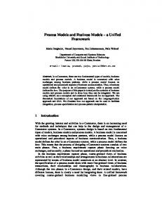
Fig. 3. Multiple cheese-cutting problem. (a) Coarse model. (b) Fine model.
B. Comments and to represent As shown in Fig. 1, we use symbols represent implied. Steps 6–8, respectively. We let operator We can see that rebuilding the surrogate (Step 7) may be implied in either the PE process (Step 6) or in the reoptimization (Step 8). Steps 6–8 are separate steps in neural SM (training data is obtained by PE, the surrogate is rebuilt by the neural-network training process, and prediction is obtained by evaluating the neural network). However, Step 7 may be implied in either the PE process (Step 6), e.g., ISM, where the surrogate is rebuilt by extracting preassigned parameters, or in the prediction (Step 8), e.g., aggressive SM, where the surrogate is not explicitly rebuilt. Step 6 can be termed “modeling” in certain cases. Fig. 1.
SM framework.
A. SM Framework Optimization Steps A flowchart of a general SM is shown in Fig. 1. Step 1) Select a coarse model suitable for the fine model. Step 2) Select a mapping process (original, aggressive SM, neural or ISM, etc.) Step 3) Optimize the coarse model (initial surrogate) with respect to design parameters. Step 4) Simulate the fine model at this solution. Step 5) Terminate if a stopping criterion is satisfied, e.g., response meets specifications. Step 6) Apply PE using preassigned parameters [5], neuron weights [10], coarse space parameters, etc. Step 7) Rebuild surrogate (may be implied within Steps 6 or 8). Step 8) Reoptimize the “mapped coarse model” (surrogate) with respect to design parameters (or evaluate the inverse mapping if it is available). Step 9) Go to Step 4.
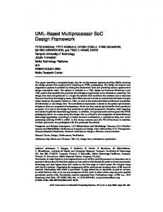
III. RRSM APPROACH A. Surrogate The response-residual surrogate is a calibrated (implicitly or explicitly space mapped) coarse model plus an output or response residual [6] (1) where and represent, respectively, the response at selected of the surrogate and the coarse model, e.g., is the number of sample points. Each frequency points residual element (sample point) may be weighted using a . From experience weighting parameter (2) The coarse-model design parameters and preassigned parameters are denoted by and . The residual is a vector whose elements are the differences between the previous calibrated coarse- and fine-model responses at each sample point after PE. The surrogate is shown in Fig. 2.
BANDLER et al.: SM DESIGN FRAMEWORK
Fig. 4. Parameter errors between the ISM algorithm (solution x = 12:2808) and MATLAB minimax direct optimization (solution x = 12).
2603
Fig. 6. Parameter difference between the RRSM design and minimax direct optimization. Finally, x = x = 12.
Fig. 7. S2P (two-port S -parameter file) symbol with terminals.
Fig. 5. “Multiple cheese-cutting” problem: step-by-step ISM and RRSM optimization.
In the PE process, we match the previous RRSM surrogate (instead of the calibrated coarse model of [6]) to the fine model at each sample point. B. Multiple Cheese-Cutting Problem [11] We develop a physical example suitable for illustrating SM optimization. Our “responses” are the weights of individual cheese slices. The designable parameter is the length of the top slice [see Fig. 3(a)]. A density of one is assumed. The goal is to cut through the slices to obtain a weight for each one as close to a desired weight as possible. Note that we measure
Fig. 8. Three-section 3 : 1 microstrip impedance transformer. (a) Structure and dimensions. (b) Coarse model.
the length from the right-hand end. We cut on the left-hand side (the broken line). The coarse model involves three slices of the same height , namely, the preassigned parameter shown in Fig. 3(a). The lengths of the two lower slices are units shorter than the top can be calculated to minimize the one. The optimal length differences between the weights of the slices and the desired weight . We use minimax optimization. The responses of the coarse model are given by
(3)
2604
IEEE TRANSACTIONS ON MICROWAVE THEORY AND TECHNIQUES, VOL. 52, NO. 11, NOVEMBER 2004
Fig. 9. Coarse-model optimization of the three-section impedance transformer. The coarse model is optimized using the minimax algorithm.
The fine model is similar, but the lower two slices are and units shorter, respectively, than the top slice [see Fig. 3(b)]. The heights of the slices are and , respectively. The corresponding responses of the fine model are
Fig. 10. Fine model of the three-section transformer simulated in ADS Momentum.
(4) We set and . The specification is set to ten. The heights of the slices are fixed at unity for the fine . The coarse-model preassigned model, i.e., parameter is initially unity. If the mismatch between the coarse and fine models is not compensated by varying certain preassigned parameters, the ISM approach may not converge to the optimal solution. Fig. 4 illustrates such nonconvergence through a MATLAB implementation of our example. For the same example, using MATLAB, we demonstrate the implicit and RRSM optimization process. Fig. 5 shows the first two iterations of the algorithm step by step. The RRSM algorithm converges to the optimal fine-model solution, as shown in Fig. 6. IV. ADS SCHEMATIC DESIGN FRAMEWORK Agilent ADS has a huge library of circuit models that can be used as “coarse” models. ADS also has a suite of easy-to-use optimization tools, e.g., random search, gradient search,
Fig. 11. Coarse- (—) and fine-model (o) responses jS of the three-section transformer.
j
at the initial solution
Quasi-Newton search, discrete search, and genetic algorithm. An -parameter file SnP in ADS can import data files ( -parameters) in a Dataset or Touchstone format. Here, is the port number. Fig. 7 is a symbol of two-port -parameter file component S2P with terminals. Many EM simulators (“fine” model) such as Sonnet Software’s em, Agilent Momentum, and Agilent HFSS support Touchstone file format. Using this file, we import
BANDLER et al.: SM DESIGN FRAMEWORK
2605
Fig. 12. Calibration of the coarse model of the three-section impedance transformer. This schematic extracts preassigned parameters x . The coarse and fine models are within the broken line. The goal is to match the coarse- and fine-model real and imaginary S from 5 to 15 GHz. The optimization algorithm uses the Quasi-Newton method.
Fig. 13. Reoptimization of the coarse model of the three-section impedance transformer using the fixed preassigned parameter values obtained from the previous calibration (PE). This schematic uses the minimax optimization algorithm. The goal is to minimize jS j of the calibrated coarse model.
2606
IEEE TRANSACTIONS ON MICROWAVE THEORY AND TECHNIQUES, VOL. 52, NO. 11, NOVEMBER 2004
-parameters and match them with the ADS circuit model (coarse model) responses in the PE procedure. The residual between the calibrated coarse and fine models can also be obtained using the SnP file and MeasEqn (measurement equation) component. These major steps of SM are friendly for engineers to apply. A. ADS Schematic Design Framework for SM Step 1) Step 2)
Set up the coarse model in ADS schematic. Optimize the coarse model using the ADS optimization algorithm. Step 3) Copy and paste the parameters into the parameterized fine model (Agilent Momentum, HFSS/ Empipe3D,8 or Sonnet Software’s em). In Momentum, the fine model can also be generated using the Generate/Update Layout command. Step 4) Simulate the fine model and save the responses in Touchstone format (Agilent Momentum, HFSS, or Sonnet Software’s em) or Dataset (Momentum); check the stopping criteria; if satisfied, stop. Step 5) Import the responses to the ADS schematic using the SnP component under Data Items. Set up ADS (calibrated) coarse-model or RRSM surrogate to match the SnP component and run the ADS optimization algorithm to perform PE. Here, you may extract the coarse-model design parameter or the preassigned parameters to implement explicit (original or aggressive SM) or ISM, respectively. Step 6) Predict the next fine-model solution by the following: a) explicit SM: transfer extracted parameters to MATLAB (or other scientific computing tool) and calculate a prediction based on the algorithm in [1], [2] or, b) ISM: reoptimize the calibrated coarse model with respect to design parameters to predict the next fine-model design and/or, c) RRSM: reoptimize the surrogate (calibrated coarse model plus response residual) with respect to design parameters to predict the next fine-model design. Step 7) Update the fine-model design and go to Step 4. We implement the SM optimization process in the ADS schematic framework in an interactive way. The following three ADS schematic designs are needed: 1) coarse-model optimization design (Steps 1 and 2); 2) PE design (Step 5); 3) surrogate (re)optimization design (Step 6). Each subsequent iteration of the framework involves only designs 2) and 3), where only the values of the parameters are updated. Currently, the fine model is Agilent Momentum, HFSS, or Sonnet Software’s em.
Fig. 14. Optimal coarse- (—) and fine-model (o) responses jS j for the three-section transformer using Momentum after one iteration (two fine-model simulations). The process satisfies the stopping criteria.
TABLE II OPTIMIZABLE PARAMETER VALUES OF THE THREE-SECTION IMPEDANCE TRANSFORMER
Fig. 15.
(a) Six-section
H -plane waveguide filter. (b) ADS coarse model.
B. Three-Section Microstrip Transformer 8Empipe3D, vers. 5.6, Agilent EESof EDA, Agilent Technol., Santa Rosa, CA, 2000.
An example of ADS implementation of ISM optimization is the three-section microstrip impedance transformer [see
BANDLER et al.: SM DESIGN FRAMEWORK
2607
H
1RR
Fig. 16. -plane filter design. (a) ADS setup for RRSM surrogate optimization. We (re)optimize the surrogate (current ADS coarse-model response plus obtained from the previous coarse-model response S55 and fine-model response S33) to satisfy the specifications. (b) ADS setup for RRSM PE. We minimize the difference between the surrogate (current ADS coarse-model response plus obtained from the previous coarse-model response S55 and previous fine-model response S77) and the current fine-model response S33. In both schematics, the current ADS coarse models used are shown in Fig. 15(b) and are omitted here to save space.
1RR
Fig. 8(a)] [12]. The coarse model is shown in Fig. 8(b). Empirical formulas express electrical parameters in terms of physical dimensions. The design specifications are for
GHz
GHz
(5)
The designable parameters are the width and physical length of each microstrip line. Here, the reflection coefficient is used to match the two model responses. The fine model is an Agilent Momentum model. The preassigned parameters of the
fine model are the substrate height and dielectric constant of each section. The height of the dielectric substrate is 0.635 mm (25 mil) and its relative permittivity is 9.7. The effect of nonideal dielectric is considered by setting the loss tangent to 0.002. We use 11 frequency points in the sweep. The first step is to obtain an optimal coarse-model design using the ADS Schematic (minimax) optimization utilities, as shown in Fig. 9. In this schematic, we show the starting point (in mils) of the coarse-model design parameter values. The coarse-model parameter conversion components implement
2608
IEEE TRANSACTIONS ON MICROWAVE THEORY AND TECHNIQUES, VOL. 52, NO. 11, NOVEMBER 2004
well-known empirical formulas [13]. The schematic will sweep -parameters in the band. When we “simulate” the schematic, ADS provides an optimal coarse-model solution. We apply the obtained design parameters to the fine model (Fig. 10). To achieve this, we can copy and paste the parameters to the parameterized Momentum fine model or create a Momentum layout from the schematic layout directly. In the fine model, the preassigned parameters are (always) kept fixed at nominal values. We obtain the fine-model response as in Fig. 11. Imported by S2P (two-port -parameter file), the fine-model real and imaginary responses are used in the PE (calibration) step (Fig. 12). In this step, the preassigned parameters of the coarse model are calibrated to match the fine- and coarse-model responses. The goal is to match the real and imaginary parts at the same time. A quasi-Newton algorithm is used of to perform this procedure. If we obtain a good match between the fine and coarse models, i.e., a set of preassigned parameter values providing the best match are found, we proceed to the next step. With fixed preassigned parameters, the new coarse model (surrogate) is reoptimized with respect to the original specification. This is done as shown in Fig. 13. This schematic is similar to Fig. 9, but with a different set of preassigned parameter values. The ADS minimax algorithm is used again in this case. We apply the prediction to the fine model again. The finemodel simulation gives a satisfactory result, as shown in Fig. 14. The initial and final solutions are shown in the Table II. It takes two fine-model simulations. V.
H
Fig. 17. -plane filter optimal coarse-model response (—), and the fine-model response at: (a) initial solution (o). (b) Solution reached via RRSM after four iterations (o). TABLE III OPTIMIZABLE PARAMETER VALUES OF THE SIX-SECTION -PLANE WAVEGUIDE FILTER
H
-PLANE FILTER DESIGN
A. Implicit and RRSM Optimization Steps We use the ADS framework exploiting ISM and RRSM to design an -plane filter. The following iterations are employed: two iterations of ISM to drive the design to be close to the optimal solution, one ISM and RRSM iteration using weighting ( because the parameters optimization algorithm has difficulty reoptimizing the surrogate with the full residual added), and a second ISM and RRSM iteration with the full residual added. B. Six-Section
-Plane Waveguide Filter
The six-section -plane waveguide filter [7], [8] is shown in Fig. 15(a). The design parameters are the lengths and widths: and . Design specifications are for frequency range for frequency for frequency
GHz GHz GHz
We use 23 sample points. A waveguide with a cross section of 1.372 0.622 in (3.485 1.58 cm) is used. The six sections are separated by seven -plane septa, which have a finite thickness of 0.02 in (0.508 mm). The coarse model consists of lumped inductances and waveguide sections. There are various approaches to calculate the equivalent inductive susceptance corresponding to
an -plane septum. We utilize a simplified version of a formula due to Marcuvitz [14] in evaluating the inductances. The coarse model is simulated using ADS, as shown in Fig. 15(b). Fig. 16(a) shows the ADS setup for RRSM surrogate optimization, and Fig. 16(b) shows the ADS setup for RRSM PE. We select the waveguide width of each section as the preassigned parameters to calibrate the coarse model. The frequency coefficient of each inductor, for convenience PI, is also harnessed as a preassigned parameter to compensate for the susceptance change. The fine model exploits Agilent HFSS . One frequency sweep takes 2.5 min on an Intel Pentium 4 (3-GHz CPU) computer with 1-GB RAM and running in Windows XP Pro. Fig. 17(a) shows the fine-model response at the initial solution. Fig. 17(b) shows the fine-model response after running the algorithm using the Agilent HFSS simulator. Since no Jacobian is needed, the total time taken for five
BANDLER et al.: SM DESIGN FRAMEWORK
fine-model simulations is 15 min on an Intel Pentium 4 (3-GHz CPU) computer. Table III shows the initial and optimal design parameter values of the six-section -plane waveguide filter.
2609
[13] D. M. Pozar, Microwave Engineering, 2nd ed. New York: AddisonWesley, 1998, pp. 162–163. [14] N. Marcuvitz, Waveguide Handbook, 1st ed. New York, NY: McGrawHill, 1951, p. 221.
VI. CONCLUSION We present and discuss a comprehensive microwave SM design framework and possible software implementations. A new “multiple cheese-cutting” design example illustrates our approach and possible pitfalls. We describe an interactive ADS implementation, illustrated step by step through a three-section microstrip transformer. We present an RRSM modeling technique that matches the RRSM surrogate with the fine model. A good -plane filter design emerges after only five HFSS simulations using the ISM and RRSM approaches with sparse frequency sweeps and no Jacobian calculations. ACKNOWLEDGMENT The authors thank Dr. J. C. Rautio, Sonnet Software Inc., Liverpool, NY, for making em available, and Agilent Technologies, Santa Rosa, CA, for ADS, Momentum, HP HFSS, and HP Empipe3D. REFERENCES [1] J. W. Bandler, R. M. Biernacki, S. H. Chen, P. A. Grobelny, and R. H. Hemmers, “Space mapping technique for electromagnetic optimization,” IEEE Trans. Microwave Theory Tech., vol. 42, pp. 2536–2544, Dec. 1994. [2] J. W. Bandler, R. M. Biernacki, S. H. Chen, R. H. Hemmers, and K. Madsen, “Electromagnetic optimization exploiting aggressive space mapping,” IEEE Trans. Microwave Theory Tech., vol. 43, pp. 2874–2882, Dec. 1995. [3] A. M. Pavio, “The electromagnetic optimization of microwave circuits using companion models,” presented at the IEEE MTT-S Int. Microwave Symp. Workshop, 1999. [4] J. Snel, “Space mapping models for RF components,” presented at the IEEE MTT-S Int. Microwave Symp. Workshop, 2001. [5] J. W. Bandler, Q. S. Cheng, N. K. Nikolova, and M. A. Ismail, “Implicit space mapping optimization exploiting preassigned parameters,” IEEE Trans. Microwave Theory Tech., vol. 52, pp. 378–385, Jan. 2004. [6] J. W. Bandler, Q. S. Cheng, D. H. Gebre-Mariam, K. Madsen, F. Pedersen, and J. Søndergaard, “EM-based surrogate modeling and design exploiting implicit, frequency and output space mappings,” in IEEE MTT-S Int. Microwave Symp. Dig., June 2003, pp. 1003–1006. [7] L. Young and B. M. Schiffman, “A useful high-pass filter design,” Microwave J., vol. 6, pp. 78–80, 1963. [8] G. L. Matthaei, L. Young, and E. M. T. Jones, Microwave Filters, Impedance-Matching Network and Coupling Structures, 1st ed. New York: McGraw-Hill, 1964. [9] J. W. Bandler, Q. S. Cheng, S. A. Dakroury, A. S. Mohamed, M. H. Bakr, K. Madsen, and J. Søndergaard, “Space mapping: The state of the art,” IEEE Trans. Microwave Theory Tech., vol. 52, pp. 337–361, Jan. 2004. [10] M. H. Bakr, J. W. Bandler, M. A. Ismail, J. E. Rayas-Sánchez, and Q. J. Zhang, “Neural space-mapping optimization for EM-based design,” IEEE Trans. Microwave Theory Tech., vol. 48, pp. 2307–2315, Dec. 2000. [11] J. W. Bandler, Q. S. Cheng, D. M. Hailu, and N. K. Nikolova, “An implementable space mapping design framework,” in IEEE MTT-S Int. Microwave Symp. Dig., June 2004, pp. 703–706. [12] M. H. Bakr, J. W. Bandler, R. M. Biernacki, and S. H. Chen, “Design of a three-section 3:1 microstrip transformer using aggressive space mapping,” Simulation Optimization Syst. Res. Lab., Dept. Elect. Comput. Eng., McMaster Univ., Hamilton, ON, Canada, Rep. SOS-97-1-R, 1997.
John W. Bandler (S’66–M’66–SM’74–F’78) was born in Jerusalem, on November 9, 1941. He studied at Imperial College of Science and Technology, London, U.K., from 1960 to 1966. He received the B.Sc. (Eng.), Ph.D., and D.Sc. (Eng.) degrees from the University of London, London, U.K., in 1963, 1967, and 1976, respectively. In 1966, he joined Mullard Research Laboratories, Redhill, Surrey, U.K. From 1967 to 1969, he was a Post-Doctorate Fellow and Sessional Lecturer with the University of Manitoba, Winnipeg, MB, Canada. In 1969, he joined McMaster University, Hamilton, ON, Canada, where he has served as Chairman of the Department of Electrical Engineering and Dean of the Faculty of Engineering. He is currently Professor Emeritus in Electrical and Computer Engineering, and directs research in the Simulation Optimization Systems Research Laboratory. He was President of Optimization Systems Associates Inc. (OSA), which he founded in 1983, until November 20, 1997, the date of acquisition of OSA by the Hewlett-Packard Company (HP). OSA implemented a first-generation yield-driven microwave CAD capability for Raytheon in 1985, followed by further innovations in linear and nonlinear microwave CAD technology for the Raytheon/Texas Instruments Joint Venture MIMIC Program. OSA introduced the computer-aided engineering (CAE) systems RoMPE in 1988, HarPE in 1989, OSA90 and OSA90/hope in 1991, Empipe in 1992, and Empipe3D and EmpipeExpress in 1996. OSA created empath in 1996, marketed by Sonnet Software Inc. He is currently President of Bandler Corporation, Dundas, ON, Canada, which he founded in 1997. He has authored or coauthored over 365 papers from 1965 to 2004. He contributed to Modern Filter Theory and Design (New York: Wiley-Interscience, 1973) and Analog Methods for Computer-aided Analysis and Diagnosis (New York: Marcel Dekker, 1988). Four of his papers have been reprinted in Computer-Aided Filter Design (New York: IEEE Press, 1973), one in each of Microwave Integrated Circuits (Norwood, MA: Artech House, 1975), Low-Noise Microwave Transistors and Amplifiers (New York: IEEE Press, 1981), Microwave Integrated Circuits, 2nd ed.(Norwood, MA: Artech House, 1985), Statistical Design of Integrated Circuits (New York: IEEE Press, 1987), and Analog Fault Diagnosis (New York: IEEE Press, 1987). He joined the Editorial Boards of the International Journal of Numerical Modeling (1987), the International Journal of Microwave and Millimeterwave Computer-Aided Engineering (1989), and Optimization Eng. in 1998. He was Guest Editor of the International Journal of Microwave and Millimeter-Wave Computer-Aided Engineering Special Issue on Optimization-Oriented Microwave CAD (1997). He was Guest Co-Editor of the Optimization Eng. Special Issue on Surrogate Modelling and Space Mapping for Engineering Optimization (2001). Dr. Bandler is a Fellow of the Canadian Academy of Engineering, the Royal Society of Canada, the Institution of Electrical Engineers (U.K.), and the Engineering Institute of Canada. He is a member of the Association of Professional Engineers of the Province of Ontario (Canada) and a member of the Massachusetts Institute of Technology (MIT) Electromagnetics Academy. He was an associate editor of the IEEE TRANSACTIONS ON MICROWAVE THEORY AND TECHNIQUES (1969–1974), and has continued serving as a member of the Editorial Board. He was guest editor of the IEEE TRANSACTIONS ON MICROWAVE THEORY AND TECHNIQUES Special Issue on Computer-Oriented Microwave Practices (1974) and guest co-editor of the IEEE TRANSACTIONS ON MICROWAVE THEORY AND TECHNIQUES Special Issue on Process-Oriented Microwave CAD and Modeling (1992). He was guest editor of the IEEE TRANSACTIONS ON MICROWAVE THEORY AND TECHNIQUES Special Issue on Automated Circuit Design Using Electromagnetic Simulators (1997). He is guest co-editor of the IEEE TRANSACTIONS ON MICROWAVE THEORY AND TECHNIQUES Special Issue on Electromagnetics-Based Optimization of Microwave Components and Circuits (2004). He has served as chair of the MTT-1 Technical Committee on Computer-Aided Design. He was the recipient of the 1994 Automatic Radio Frequency Techniques Group (ARFTG) Automated Measurements Career Award and the 2004 Microwave Application Award presented by the IEEE MTT-S.
2610
IEEE TRANSACTIONS ON MICROWAVE THEORY AND TECHNIQUES, VOL. 52, NO. 11, NOVEMBER 2004
Qingsha S. Cheng (S’00) was born in Chongqing, China. He received the B.Eng. and M.Eng. degrees in automation from Chongqing University, Chongqing, China, in 1995 and 1998, respectively, and the Ph.D. degree from McMaster University, Hamilton, ON, Canada, in 2004. In September 1998, he joined the Department of Computer Science and Technology, Peking University, Beijing, China. In September 1999, he joined the Simulation Optimization Systems Research Laboratory, Department of Electrical and Computer Engineering, McMaster University, where he is currently a Post-Doctoral Fellow. His research interests are computer-aided design (CAD), modeling of microwave circuits, software design technology, and methodologies for microwave CAD. Dr. Cheng was the recipient of a one-year Nortel Networks Ontario Graduate Scholarship in Science and Technology (OGSST) for the 2001–2002 academic year.
Daniel M. Hailu (S’99) was born in Winnipeg, MB, Canada, in 1979. He received the B.Eng. degree (with distinction) in computer engineering from McMaster University, Hamilton, ON, Canada, in 2002. In May 2002, he joined the Simulation Optimization Systems Research Laboratory and the Department of Electrical and Computer Engineering, McMaster University, as a graduate student. His research interests are in CAD and modeling of microwave circuits, EM optimization, SM technology, OSM, device modeling, and CAD methods for antennas. Mr. Hailu was awarded honors for a statewide geometry test in California 1995. He was on the Dean’s Honor List from 1998 to 2003. He was the recipient of the 2001–2002 Dr. Rudolf de Buda Scholarship for academic achievement and the 2002–2003 Natural Sciences and Engineering Research Council Undergraduate Student Research Award (NSERC USRA).
Natalia K. Nikolova (S’93–M’97) received the Ph.D. degree from the University of Electro-Communications, Tokyo, Japan, in 1997. From 1998 to 1999, she was with the Natural Sciences and Engineering Research Council of Canada (NSERC), during which time she was initially with the Microwave and Electromagnetics Laboratory, DalTech, Dalhousie University, Halifax, NS, Canada. For a year, she was then with the Simulation Optimization Systems Research Laboratory, McMaster University, Hamilton, ON, Canada. In July 1999, she joined the Department of Electrical and Computer Engineering, McMaster University, where she is currently an Associate Professor. Her research interests include theoretical and computational electromagnetism, high-frequency analysis techniques, as well as computer-aided design (CAD) methods for high-frequency structures and antennas. Dr. Nikolova was the recipient of an NSERC Post-Doctoral Fellowship from 1998 to 1999. She currently holds the 2000 NSERC University Faculty Award.