Energies 2014, 7, 5922-5952; doi:10.3390/en7095922 OPEN ACCESS
energies ISSN 1996-1073 www.mdpi.com/journal/energies Article
A STATCOM with Supercapacitors for Low-Voltage Ride-Through in Fixed-Speed Wind Turbines Andrés Felipe Obando-Montaño, Camilo Carrillo *, José Cidrás and Eloy Díaz-Dorado Department of Electrical Engineering, University of Vigo, EEI, Campus Universitario. s/n, Vigo 36310, Spain; E-Mails:
[email protected] (A.F.O.-M.);
[email protected] (J.C.);
[email protected] (J.C.) * Author to whom correspondence should be addressed; E-Mail:
[email protected]; Tel.: +34-986-813912; Fax: +34-986-812173. Received: 26 June 2014; in revised form: 20 August 2014 / Accepted: 3 September 2014 / Published: 10 September 2014
Abstract: Fixed-speed wind generator (FSWG) technology has an important presence in countries where wind energy started to be developed more than a decade ago. This type of technology cannot be directly adapted to the grid codes, for example those requirements related to the immunity level under voltage dips. That behavior is typically referred as low-voltage ride through (LVRT), and it usually implies certain reactive and active power injection requirements, both during a voltage dip and during the voltage recovery. In this context, a review is presented of the LVRT exigencies present in some of the countries with the most advanced grid codes (Denmark, Germany, Spain and the United Kingdom). In this paper, the capabilities of STATCOM-based devices for fulfilling the LVRT requirements in FSWGs are analyzed. For this purpose, two technologies are considered: a STATCOM with a supercapacitor, which improves its energy storage features; and a STATCOM with a supercapacitor and a DC-DC converter, to achieve higher discharge levels. Keywords: wind energy; fixed-speed wind generator; STATCOM; supercapacitor; low-voltage ride-through
1. Introduction Currently, wind power is the most promising renewable energy source due its increasing penetration in the world’s energy mix. For example, in the European Union at the end of 2012, the installed capacity
Energies 2014, 7
5923
reached 100 GW, and 11% of the electricity generated in the European Union was from wind energy [1,2]. In this context, system operators (SOs) are becoming stricter with the use of wind energy sources in terms of their behavior compared with conventional energy sources. This restricted use of wind energy sources is implemented through a continuous updating of their grid codes, where the technical conditions demanded for renewable power plants are stricter, or even more exigent, than those for conventional power plants. Regarding these grid codes, typically one of the most demanding requirements is the low-voltage ride-through (LVRT) capability. This requirement refers to the ability of a generating unit or power plant to withstand a voltage dip, whose profile is established by the SO in the grid code. Furthermore, grid codes usually establish the required behavior in terms of the active and reactive power generation during this voltage dip [3–7]. From the point of view of the technology of wind turbine generators (WTGs), most of the WTGs installed during the boom of wind energy were fixed speed wind generators (FSWGs) formed by induction generators [8]. However, in recent years, the most frequently installed WTGs were variable-speed wind turbines formed by doubly-fed induction generators or by synchronous generators with back-to-back converters [9]. Despite this market tendency, FSWGs have an important presence in countries where wind energy started to be developed more than a decade ago (e.g., in 1995, 70% of the market was dominated by Squirrel Cage Induction Generators, which decreased to 25% by 2004) [8,10]. According to the Spanish Wind Energy Association (Asociación Empresarial Eólica AEE), by 2009, the total installed wind power capacity was 16.740 MW, and those wind turbines with induction generators represented 20% (3380 MW) [11]. In FSWGs, the induction generator is directly connected to the grid, which makes it difficult for this technology to fulfill almost any grid code requirement. For example, FSWGs are usually disconnected when the voltage drop exceeds 10%–20% with respect to the rated voltage [12]. Commonly, FSWGs have mechanically switched capacitors to assist them with the power factor; however, for LVRT fulfillment, reactive power compensators, such as static VAR compensators (SVC) and static synchronous compensators (STATCOM) [9,13,14], must be used. A STATCOM is a reactive power compensator that exhibits a good dynamic response with a high control bandwidth and the capability of providing higher currents at low voltage levels [12]. It is also desirable to use a STATCOM due to the possibility of working with decoupled control of the DC-link voltage and the reactive current [15]. However, one of the main drawbacks is the low energy density on the DC link capacitor installed in the STATCOM; this limits the reactive and active power capability of the STATCOM [16,17]. An improved version of the STATCOM is called the STATCOM + ES (energy storage). This variant includes a storage device, usually batteries, supercapacitors (SCs), etc. The storage device provides more capabilities to the STATCOM, such as power oscillation damping or mitigation of phase-jump-related disturbances [18–24]. Moreover, the STATCOM + ES can be used for reactive compensation when an LVRT system is implemented [25,26]. The main objective of this paper is to propose a robust and reliable solution that provides FSWG LVRT capability, allowing these types of generators to withstand voltage dips and comply with different grid code requirements. The proposed approach to accomplish this purpose is the use of a STATCOM + ES-based on an SC, which enables not only the fulfillment of the reactive power requirements during a voltage dip, but also the active power requirements, i.e., a complete fulfillment of the LVRT conditions can be achieved. The capability of active power generation is implemented by
Energies 2014, 7
5924
means of an SC and a DC-DC converter in the DC link of the STATCOM [23,27]. One of the main features of SCs is their high energy density and large time constants, which makes them very suitable for short-term applications, such as voltage dips, where the disturbances always last less than a second [21,28] (see Appendix 1 for commercially available SCs). In this study, the grid codes of the following countries are analyzed to establish the LVRT requirements used to define and simulate the compensation system: Denmark, Germany, Spain and the United Kingdom (UK). The paper is organized as follows. Section 2 summarizes the LVRT requirements in the grid codes. Section 3 presents the system model, including the STATCOM description. Section 4 presents the proposed compensations systems. Section 5 presents the system control with the decoupled control capability. In Section 6, the method implemented for the simulations is presented. In Section 7, the results of all of the simulations are presented, and finally, the conclusions are presented in Section 8. 2. LVRT Requirements in the Grid Codes One of the most severe types of disturbances in a power network is a voltage dip. According to international standards, voltage dips are characterized by a temporary reduction of the voltage below a threshold that can last from milliseconds up to minutes [29]. Generally, these voltage dips are caused by short circuits in the transmission network. Due to these faults and with the aim of restoring the network to its pre-fault value, the grid codes require that all generation units, including WTGs, must back up the grid. This requirement is called LVRT, and it requires the WTGs to remain connected to the grid, even if, in some cases, the faults reduce the voltage to zero at the point of common coupling (PCC). Furthermore, limits to the active and reactive power consumption during a voltage dip are established in the grid codes [14]. This paper is focused on analyzing the LVRT behavior of FSWGs, because this is typically one of the most demanding requirements from a technologic point of view. The countries whose grid codes have been taken into account are Denmark, Germany, Spain and the United Kingdom. 2.1. Denmark The Danish grid code has two separate requirements for the connection of WTGs to the grid, one for voltages below 100 kV and the other one for voltages above 100 kV. In this paper, the LVRT requirements regarding the voltages above 100 kV [4] are considered due to them being more demanding (e.g., active power generation) and also because the profile in both codes is the same. In Figure 1, the voltage profile is shown that the WTGs must withstand without disconnection. This profile is only valid for three-phase short circuits. This code also establishes that the wind farm shall produce the rated power no later than 10 s after the voltage recovers the 0.9 p.u. (per-unit system) during the voltage dip. The active power in the PCC shall meet the following condition:
Pactual
U kp Pt 0 actual U t 0
2
(1)
Energies 2014, 7
5925
where:
Pactual: the actual active power measured in the PCC; Pt = 0: the power measured in the PCC immediately before the voltage dip; Ut = 0: the voltage in the PCC immediately before the voltage dip; Uactual: the actual voltage measured in the PCC; Kp = 0.4: the reduction factor considering any voltage dips at the generator terminals.
During the voltage dip, the wind farm is allowed to consume a reactive current equal to the nominal current at most. The Danish SO also established the use of a simulation model that shall be based on the Thévenin equivalent of the power system. In this equivalent, the grid impedance is characterized by a short-circuit power ten-times higher than the wind turbine’s rated power and an impedance ratio of 0.1 [4]. Figure 1. Low-voltage ride-through (LVRT) profile in the Danish grid code.
2.2. Germany The LVRT restrictions given by the German grid code [3] establish two different borderlines that the WTG must accomplish to interconnect with the grid (see Figure 2). This paper will study the behavior of the profile given by Borderline 2, due it being the most demanding one. The conditions for this type of voltage dip are:
Above Borderline 2, all generating facilities must pass through the fault without being disconnected from the network; Below Borderline 2, short-time disconnections are always permitted, but the resynchronization must occur after 2 s. Active power feed-in must be increased with a gradient of at least 10% of the nominal generator capacity per second of the original value; For all generating facilities that are not disconnected from the network during a fault, an active power supply must be continued immediately after the fault clearance and increased to the original value with a gradient of at least 20% of the nominal capacity per second; The generating facilities must contribute to the network stability during a voltage dip by means of additional current. For this purpose, a voltage control according to Figure 3 shall be activated
Energies 2014, 7
5926
in the event of a voltage dip of more than 10% of the effective value of the generator voltage. This voltage control must ensure the supply of a reactive current at the low-voltage side of the generator transformer with a contribution of at least 2% of the rated current for each percent of the voltage dip. The facilities must be capable of feeding the required current within 20 ms into the grid. If necessary, a reactive power output of at least 100% of the rated current must be possible. Figure 2. LVRT profile in the German grid code.
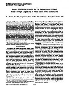
Figure 3. Reactive output current under disturbances according to the German grid code (Vn, nominal voltage; V, instantaneous voltage during the disturbance; In, nominal current; Ir, reactive current).
∆Ir/In (%) Dead band
Limitation of voltage through voltage control (under excited operation)
Dead band limits: Vmax = 1.1Vn Vmin = 0.9Vn -50
Ir max ≥ In
-10 10 20
-100
∆V/Vn (%)
Energies 2014, 7
5927
2.3. Spain The LVRT requirements that a WTG must withstand to allow its connection to the Spanish grid are summarized in the operation procedure P.O. 12.3 [7]. In Figure 4a is shown the voltage profile that the WTG must ride through without disconnection, and Figure 4b shows the reactive current response during the voltage dip. There are other requirements demanded by the Spanish SO to support the grid; according to these requirements, the LVRT profile is divided into three zones [30] (see Figure 4a):
Zone 1 starts after the fault and lasts 150 ms; Zone 2 is during the fault, between Zone 1 and Zone 3; Zone 3 starts when the fault is cleared and the voltage begins to recover to its pre-fault value. Figure 4. (a) LVRT profile and (b) reactive current response, according to the Spanish grid code.
In the Spanish grid code, certain active and reactive power consumption is allowed in all three zones, as shown in Table 1. For example, in Zone 1, during the first 0.35 s, the WTG cannot consume more than the 60% of the nominal active power.
Energies 2014, 7
5928
Table 1. Active and reactive requirements during three phase faults. WTG, wind turbine generator. Spanish grid code requirements Active power (P) Reactive power (Q) Reactive energy (Er) Reactive current (Ir)
Zone 1 No limit