A New Single-Phase Inverter with D-STATCOM Capability for Grid-connected Small Wind Turbines Pedram Sotoodeh, and Ruth Douglas Miller Electrical and Computer Engineering Department, Kansas State University, Manhattan, Kansas 66506, USA Corresponding email:
[email protected] is used to perform a specific function in a system. There are a number of advantages to use power electronic devices, but the most important is the capability to control and manage the flow of electrical power. Using power electronics has made it possible to connect AC or DC sources with different voltage or frequency levels to each other. Among all power quality concerns, controlling the active and reactive power transferring to or from the grid requires major attention. Power electronic-based flexible AC transmission System (FACTS) devices have been developed in order to provide more knowledge and control on power systems. Traditionally, capacitor banks have been used to control the reactive power on a power grid, but with deployment of power electronics in power systems, STATCOMs were born and received more and more attention during recent years. The aim of this work is to combine the two concepts of inverters and D-STATCOMs into a so-called D-STATCOM inverter in order to enjoy the benefits of an inverter with DSTATCOM capability without any additional cost. A multilevel D-STATCOM inverter is a power electronic device that is placed between a renewable energy source and a distribution grid not only to provide active power, but to control reactive power on the system. Multi-level converters have several advantages compared to the conventional twolevel converter. They have the capability to perform at a lower switching frequency, they have lower total harmonic across switches distortion (THD), and they have less and therefore less voltage stress on the devices [2-6]. The proposed D-STATCOM inverter in this paper could replace existing inverters used for renewable energy systems, specifically for small- to mid-sized wind applications. The D-STATCOM inverter is a cost-effective inverter with a DSTATCOM’s capability to regulate active and reactive power on distribution systems. Deployment of DSTATCOM inverters can provide utilities with more information and control, specifically at end points that utilities do not monitor adequately. The unique contribution of this work is to combine the two concepts of inverter and D-STATCOM using modular multi-level converter (MMC) topology in a single unit, which is in series with the renewable energy source, without any additional cost. Fig. 1 shows a complete configuration of the proposed MMC inverter with FACTS capabilities.
Abstract— This paper presents the design of a novel multi-level D-STATCOM inverter for renewable energy systems using modular multi-level converter (MMC) topology. The aim of the work is to design a new type of inverter with FACTS capabilities to provide utilities with more knowledge about the distribution systems, specifically on end points. The inverter is placed between the renewable energy source, specifically a wind turbine, and the distribution grid in order to regulate the active and reactive power required by the grid. This inverter is capable of controlling active and reactive power by controlling its phase angle and modulation index, respectively. The unique contribution of the proposed work is to combine the two concepts of inverter and D-STATCOM using a novel voltage source converter (VSC) multi-level topology in a single unit without any additional cost. Simulations of the proposed inverter, with 5 levels, have been completed in Matlab/Simulink. The simulation results validate the performance of the proposed control strategy.
Keywords—Multi-level Inverter, Modular Multi-level Converter (MMC), STATCOM, Wind Applications
I.
INTRODUCTION
The electric utility industry has begun to update more and more in recent years. New issues such as global warming, toxic emissions, energy cost, a broadening power market, and increasing demand have affected the growth of the power industry. Over the past decade, the willingness of utilities to invest in large-scale power plants has decreased and utilities have started shifting to smaller distributed energy sources closer to loads [1]. Renewable energy systems offer several advantages over conventional energy sources such as natural gas or coal. They are clean sources of energy that can be found in most regions without emitting any greenhouse gases. Renewable energy is abundant and free, and generally not affected by political instability. The main disadvantage of renewable energy sources is that they are mostly located in remote areas and far away from large loads. In addition, the use of renewable energy sources is limited by the fact that they are not always available. Nowadays, with recent developments in semiconductor technologies, power electronic devices have been enormously deployed in power systems to control the active and reactive power flow. A power electronic device is one that consists of a number of semiconductor components that
978-1-4673-5602-2/13/$31.00 ©2013 IEEE
175
Fig. 1. Complete configuration of the proposed D-STATCOM inverter system
II.
is able to provide utilities with distributive control of VAR compensation and power factor (PF) on feeder lines. To enhance the reactive power control of the proposed inverter, it is equipped with the additional D-STATCOM option. This option permits the inverter to deliver reactive power fully independent from the wind speed. When the wind speed is too low to generate active power, the inverter acts as a source of reactive power to control the PF of the grid, like a D-STATCOM. The inverter is able to control the active and reactive power regardless of the input active power required by the DC link. Generally, there are two modes of operation for D-STATCOM inverter when it is connected to the grid: 1) when active power is gained from the wind turbine, which is called inverter mode, 2) when no active power is gained from the wind turbine, which is called D-STATCOM mode. The active and reactive power flow of the D-STATCOM is governed by:
PROPOSED D-STATCOM INVERTER
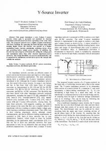
At this time, the modular multilevel converter (MMC) is the newest topology for large scale commercial applications [7-8]. Fig. 2 shows the configuration of the MMC topology. The structure of this topology is based on several modules in which each module consists of a floating capacitor and two switches. This topology is an ideal choice for FACTS applications if the capacitor voltages are kept balanced. It requires only one DC source which is proper for renewable energy inverters, it is easy to design for higher levels, and it can deliver active and reactive power regardless of the load characteristics. MMC has a modular design based on identical converter cells [9-11] which make it a suitable choice for high-level applications. The main drawback of this topology is that it requires large capacitors in comparison with similar topologies which may affect the total cost of the inverter. However, this problem can be alleviated by the lack of need for any snubber circuits. Each leg of an n-level MMC inverter consists of several basic submodules (SMs) and two inductors which are in series. This and therefore the voltage stress across the lowers switches.
sin
(1)
, , , and are the voltage of the Where STATCOM, voltage of the line, power angle, modulation index, and inductance between the inverter and the grid, respectively. The steady state operation of the D-STATCOM inverter is controlled by adjusting and , so that it provides the desired amount of active power and reactive compensation. The modulation index is used to control the active power while the power angle is used to control the reactive power transferring between the wind turbine and the grid. Fig. 3 shows the proposed control system. The control system consists of three separate parts. The first part is to define the modulation index which is done by comparing the actual reactive power on the grid with the required reactive power considering the target power factor (PF). The second part is to define the power angle which is done by comparing the DC link voltage with a reference voltage defined by the specifications of the inverter. The defined values of modulation index and power angle are applied to the reference sinusoidal signal which is required to generate the PWM signals. The third part of the control system is to select the required SMs to generate the proper gate signals. Generally, the controller measures the SMs’ capacitor voltages and sorts them in descending order. The suitable switching pattern will be chosen based on the direction of the current flowing through the switches.
Fig. 2. Configuration of the MMC topology and its sub-module
III.
&
PROPOSED CONTROL STRATEGY
This inverter is designed to control the flow of active and reactive power between the wind turbine and the grid. It
176
Fig. 3. The proposed controller system
time frame is between the 7th second and the 10th second in which the input power from the wind turbine ramps up to 7 kW. In the last time frame the input power ramps down to 1.5 kW in four seconds and remains constant around 3.5 kW. In this case, the active and reactive loads of the grid are 50 kW and 34.8 kVAR making the power factor 0.82. The function of the inverter is to keep the PF constant on the target PF which is assumed to be 0.90. As soon as the inverter provides VAR compensation, the amount of the VARs provided by the grid to the load is decreased to 22 kVAR. After the 7th second, the active power provided to the load by the grid is decreased when the input power of the inverter form wind turbine is increased. The target power factor on the grid is set to 0.90 while the load is demanding a power factor of 0.82. Therefore, the DSTATCOM tries to inject reactive power to the grid to increase the power factor of the grid. The simulated output voltage of the D-STATCOM inverter before filter is shown in Fig. 4. Fig. 5 shows the power factor of the grid which is constant on the target PF of 0.90 regardless of the input power from wind turbine.
To maintain the SM capacitor voltages balanced, a carrier-based PWM (CPWM) method is used to control the voltages of the capacitors [12-13]. For a 5-level MMC inverter, this technique requires four in-phase carriers that are displaced with respect to the zero-axis. The output voltage level is determined by comparing a sinusoidal signal reference with these four carriers. In a 5-level inverter, at each instant four SMs should be chosen based on their capacitor voltages considering the direction of the current. Depending on the output voltage level, if the current is positive, the SM capacitors are being charged, and therefore a number of SMs with lowest capacitor voltage should be chosen. Likewise, if the current is negative, the SM capacitors are being discharged, and therefore a number of SMs with highest capacitor voltage should be chosen. Generally, when the output voltage of a SM is equal to zero, it is called Off and when the out voltage of a SM is equal to its capacitor voltage, it is called On. The number of required SMs for each voltage level is as follows: for voltage level 1, , all the four upper SMs should be On in which and all the lower SMs should be Off. For voltage level 2, in , three upper SMs and one lower SM which should be On and the other SMs should be Off. For voltage 0, two upper and two lower SMs level 3, in which should be On and the others should be Off. For voltage level , one upper SM and three lower SMs 4, in which should be On and the other SMs should be Off. For voltage , all the upper SMs should be Off level 5, in which and all the four lower SMs should be On. Considering this algorithm, the voltages of the capacitors are maintained balanced and the proper gate signals can be chosen. IV.
SIMULATION RESULTS
All the simulations of the proposed 5-level MMC inverter were done in MATLAB/Simulink. The time of the simulation is 20 seconds which divides into three time frames. The first time frame is before the 7th second being assumed that the wind speed is too low or zero. The second
Fig. 4. Output voltage of the D-STATCOM inverter
177
V.
Power angle and modulation index are shown in Fig. 6, respectively.
CONCLUSIONS
In this proposal the concept of a D-STATCOM inverter is presented. The proposed inverter suggests a new way in which small renewable sources can be used to provide control and support in distribution systems. The MMC DSTATCOM inverter has the ability to provide utilities with capacitive VAR compensation. The unique work of this research is to combine the two concepts of D-STATCOM and inverter using the most advanced multi-level topology to make a single unit called D-STATCOM inverter. In the current research a new D-STATCOM inverter using the most advanced multi-level topology called MMC is presented. In this project, MMC is used as the voltage source converter (VSC) topology to make a D-STATCOM that is not only able to regulate reactive power, but is able to link to a wind turbine and regulate the active power transferred to the grid. The proposed device provides an inverter and D-STATCOM in a single unit without any additional cost. The proposed DSTATCOM inverter can provide utilities with more knowledge at end points of the distribution lines. The goal is to increase the penetration of renewable energy systems, specifically wind, to the distribution systems.
Fig. 5. Power factor of the grid
REFERENCES
Fig. 6. Power angle and modulation index
[1]
J.T. Bialasiewicz, “Renewable energy systems with photovoltaic power generators: Operation and Modeling”, Ind. Electronics, IEEE Trans. on, vol. 55, pp. 2752-2758, 2008
[2]
J. Rodriguez, J. S. Lai and F. Z. Peng, “Multilevel inverters: Survey of topologies, controls, and applications,” Industry Applications, IEEE Transactions on, vol. 49, no. 4, pp. 724-738, 2002
[3]
F. Z. Peng, J. S. Lai, J. W. McKeever, J. VanCoevering, “A multilevel voltage-source inverter with separate DC sources for static var generation,” Industry Applications, IEEE Transactions on, vol. 32, no. 5, pp. 1130-1138, 1996
[4]
L. M. Tolbert, F. Z. Peng, “Multilevel converters as a utility interface for renewable energy systems,” in Proceedings of 2000 IEEE Power Engineering Society Summer Meeting, pp. 1271-1274, 2000
[5]
Kouro, S., Malinowski, M., Gopakumar, K., Pou, J., Franquelo, L.G., Bin Wu, Rodriguez, J., Pérez, M.A., Leon, J.I., “Recent advances and industrial applications of multilevel converters”, IEEE Electronics, IEEE Transaction on, vol. 57 , no. 8, pp. 2553–2580, 2010
[6]
C. Tareila, P. Sotoodeh, R. D. Miller., “Design and control of a singlephase D-STATCOM inverter for wind application”, Power Electronics and Machines in Wind Application PEMWA 2012, Denver, Co, 2012
[7]
M. Davies, M. Dommaschk, J. Dorn, J. Lang, D. Retzmann, and D. Soerangr, “HVDC PLUS basic and principle of operation,” Siemens AG Energy Sector, Erlandgen, Germany, 2009
[8]
B. Gemmell, Siemens USA, J. Dorn, D. Retzmann, D. Soerangr, Siemens Germany, “Prospects of multilevel VSC technologies for power transmission,” in Proc. IEEE Transmission and Distribution Conference and Exposition, pp. 1-16, 2008
[9]
R. Marquardt and A. Lesnicar, "New concept for high voltage – modular multilevel converter," Power Electronics Specialists Conference, Aachen, Germany, 2004
[10] A. Lesnicar and R. Marquardt, "An innovative modular multilevel converter topology suitable for a wide power range," IEEE Power Tech Conference Proceedings, Bologna, Italy, 2003 [11] M. Saeedifard, R. Iravani, “Dynamic performance of a modular multilevel back-to-back HVDC system”, Power Delivery, IEEE Trans. On, vol. 25, no. 4, pp. 2093-2912, 2010
Fig. 7. Active and reactive power of the feeder line, active and reactive power of the D-STATCOM inverter, and the output power of the wind turbine
178
[12] J. Kim, S. Sul, P. Enjeti., “ A carrier-based PWM method with optimal switching sequence for a multilevel four-leg voltage-source inverter” , Industry Applications, IEEE Transactions on , vol. 44, no. 4, pp.1239-1248, 2008
for a three-level neutral-point-clamped converter”, Power Electronics, IEEE Transactions on, vol. 27, no. 2, pp. 642-651, 2012
[13] J. Pou, J. Zaragoza, S. Ceballos, M. Saeedifard, D. Boroyevich, “A carrier-based PWM strategy with zero- sequence voltage injection
179