Earth Surf. Dynam. Discuss., https://doi.org/10.5194/esurf-2018-53 Manuscript under review for journal Earth Surf. Dynam. Discussion started: 6 July 2018 c Author(s) 2018. CC BY 4.0 License.
A Structure from Motion photogrammetry-based method to generate sub-millimetre resolution Digital Elevation Models for investigating rock breakdown features Ankit K. Verma1 and Mary C. Bourke1 5
1
Department of Geography, Trinity College Dublin, The University of Dublin, Dublin, Ireland
Correspondence to: Ankit K. Verma (
[email protected])
Abstract We have generated sub-millimetre resolution DEMs of weathered rock surfaces using SfM photogrammetry
10
techniques. We apply a close-range Structure from Motion (SfM) photogrammetry-based method in the field and use it to generate high-resolution topographic data for weathered boulders and bedrock. The method was pilot tested on extensively weathered Triassic Moenkopi Sandstone outcrops near Meteor Crater in Arizona. Images were taken in the field using a consumer grade DSLR camera and were processed in commercially available software Agisoft Photoscan to build dense point cloud. Dense point clouds were registered to a local 3D coordinate
15
system (x, y, z) which was developed using a specially designed triangle coded control target and then exported as Digital Elevation Models (DEMs). The accuracy of the DEMs was validated under controlled experimental conditions. A number of checkpoints were used to calculate errors. We also evaluated the effects of image and camera parameters on the accuracy of our DEMs. We report a horizontal error of 0.5 mm and vertical error of 0.3 mm in our experiments. Our approach provides a low-cost method, for obtaining very high-resolution topographic
20
data on weathered rock surfaces (area < 10 m2). The results from our case study confirm the efficacy of the method at this scale and show that the data acquisition equipment is sufficiently robust and portable. This is particularly important for field conditions in remote locations or steep terrain where portable and efficient methods are required.
25
Keywords Rock breakdown, Geomorphology, Structure from Motion, Close-range photogrammetry, Digital Elevation Model, Micro-topographic survey
30
1
Earth Surf. Dynam. Discuss., https://doi.org/10.5194/esurf-2018-53 Manuscript under review for journal Earth Surf. Dynam. Discussion started: 6 July 2018 c Author(s) 2018. CC BY 4.0 License.
1.
Introduction
Rock breakdown describes a range of geomorphic processes that transform rock masses into soil or regolith and unconsolidated rock materials. It plays a vital role in climate control via atmosphere-lithosphere interaction, biogeochemical cycling and landform evolution on a planetary scale (Goudie and Viles, 2012). The scale of
5
features range from µm (e.g., fractures, weathering pits, fractures) to m scale (e.g., tafoni, scaling and blisters) (Viles, 2001; Bourke and Viles, 2007). In addition, many active rock breakdown processes that operate over a short geological timescale (100-102 years) produce observable microscale (mm-cm) breakdown features.
Quantitative analysis of landforms is necessary for the identification and interpretation of landform genesis and
10
history. In the past few decades, a range of micro-topographic data collection methods have been used in rock breakdown and soil erosion studies. These include: (1) laser scanning techniques (Fardin et al., 2001; Fardin et al., 2004; Bourke et al., 2007; Bourke et al., 2008; Aguilar et al., 2009; Sturzenegger and Stead, 2009; MŁynarczuk, 2010; Medapati et al., 2013; Chen et al., 2014; Ge et al., 2014; Lai et al., 2014), (2) stereophotogrammetry (Rieke‐Zapp and Nearing, 2005; Taconet and Ciarletti, 2007; Aguilar et al., 2009; Bui et
15
al., 2009; Sturzenegger and Stead, 2009; Kim et al., 2015), (3) Micro-roughness meters (MRM) (McCarroll, 1992; McCarroll and Nesje, 1996; White et al., 1998) . However, there are significant logistical, technical and financial constraints that have hindered the adoption of these methods, particularly in physically challenging terrains such as remote, difficult to access and steep terrains.
20
Laser scanning permits collection of high-resolution topographic data at the relevant scale for the study of smallscale rock breakdown features. However, due to difficulties associated with transporting the often-cumbersome instrument in the field (Ehlmann et al., 2008), this technology has rarely been used to collect data on rock surfaces in situ (Fardin et al., 2004). Additionally, laser scanners require a stable platform, on which to operate and this can be difficult to find in steep terrain (e.g. crater and canyon walls, and mountainous terrain). There are hand-
25
held portable laser scanners available which do not require a stable platform to operate, but the resolution offered by them is currently insufficient to resolve mm-cm scale rock breakdown features (Chan et al., 2016). Stereophotogrammetry is a method of DEM generation using stereo images of an object/surface. It is widelyapplied in terrestrial and planetary terrains (Kim and Muller, 2009; Li et al., 2011). The knowledge of camera internal geometry (i.e. sensor type and size), camera calibration parameters and Ground Control Points (GCPs)
30
with known coordinates along with inertial measurement parameters (i.e., yaw, pitch and roll) are critical requirements for stereo photogrammetry to solve collinearity equation and orient photogrammetric model (Taconet and Ciarletti, 2007; Aguilar et al., 2009). While both methods have been effectively used to analyse rock breakdown at larger scales. We have found limitations in their use in higher resolution applications. In our fieldwork, we found the techniques to be time-
35
consuming, particularly for the acquisition of appropriate resolution data. In addition, they can require significant investment in equipment and software. Both traditional photogrammetry and laser scanning techniques require expensive software (e.g. SocetSet, PHOTOMOD, FARO Scene, Trimble RealWorks, Leica CYCLONE, VisionLidar) and expert knowledge to process data and generate DEMs, the cost of which may push this technology beyond many academic research budgets.
2
Earth Surf. Dynam. Discuss., https://doi.org/10.5194/esurf-2018-53 Manuscript under review for journal Earth Surf. Dynam. Discussion started: 6 July 2018 c Author(s) 2018. CC BY 4.0 License.
The micro-roughness meter (McCarroll, 1992; McCarroll and Nesje, 1996; White et al., 1998) is operated manually and has been used to characterise and quantify breakdown on rock surfaces. It can be a time-consuming task (Gómez‐Pujol et al., 2006). Moreover, the topographic data obtained is one dimensional and limits the analysis to the calculation of profile roughness parameters. Direct physical access to the rock surface is also
5
required, which limits sampling of out of reach locations (McCarroll and Nesje, 1996). 1.1. Structure from Motion (SfM) Structure from Motion (SfM) is an established and widely used method to generate 3D models in the geosciences (Favalli et al., 2012; Westoby et al., 2012; Smith et al., 2016). It is increasingly used in geomorphology for characterisation of topographic surfaces and analysis of spatial and temporal geomorphic changes, with an
10
accuracy comparable to existing laser scanning and stereo photogrammetry techniques in close range scenario (Aguilar et al., 2009; Thoeni et al., 2014; Smith et al., 2016; Wilkinson et al., 2016). SfM photogrammetry utilises a sequence of overlapping digital images of a static subject taken from different spatial positions to produce a 3D point cloud. Image metadata for image matching is used to estimate 3D geometry and camera positions using bundle adjustment algorithm (Smith et al., 2016). The workflow uses an automated Scale Invariant Feature
15
Transform (SIFT) image matching method (Smith et al., 2016). The advancement in new image matching algorithms has eased and automated the SfM workflow compared to stereophotogrammetry (Remondino et al., 2014; Smith et al., 2016). Applications in geomorphology include laboratory flume experiments (Morgan et al., 2017), rockslides and landslide (Niethammer et al., 2012; Russell, 2016), eroding badlands (Smith and Vericat, 2015), fluvial
20
morphology (Javernick et al., 2014; Dietrich, 2014; Bakker and Lane, 2016; Dietrich, 2016a, b), peatland microforms (Mercer and Westbrook, 2016), glacial processe dynamics (Piermattei et al., 2016; Immerzeel et al., 2017), river restoration (Marteau et al., 2016), mapping coral reefs (Casella et al., 2016), beach surveying (Brunier et al., 2016), soil erosion (Snapir et al., 2014; Balaguer-Puig et al., 2017; Prosdocimi et al., 2017; Vinci et al., 2017; Heindel et al., 2018), volcanic terrains (James and Robson, 2012; Bretar et al., 2013; Carr et al., 2018),
25
porosity of river bed material (Seitz et al., 2018), grain size estimation of gravel bed rivers (Pearson et al., 2017) and coastal erosion (James and Robson, 2012). The increased uptake of this method is primarily due to its relatively low cost, high portability, and ease of data processing workflow. Much of the SfM workflow is automated in a range of relatively affordable commercial (e.g. Agisoft Photoscan, SURE, Photomodeler), closed source free software (e.g. VisualSfM, CMPMVS), and
30
open source software (e.g., Bundler, OpenMVG, OpenMVS, MicMac, SFMToolkit). There is a considerable amount of available literature on SfM techniques and workflows. For a detailed discussion of SfM techniques and workflows we recommend (Westoby et al., 2012; Fonstad et al., 2013; Thoeni et al., 2014; Micheletti et al., 2015a, b; Eltner et al., 2016; Ko and Ho, 2016; Smith et al., 2016; Schonberger and Frahm, 2016; Bedford, 2017; Zhu et al., 2017;Ozyesil et al., 2017).
35
Several studies have reported a high accuracy in 3D topographic data obtained using SfM when compared to existing methods such as Terrestrial Laser Scanner (TLS) or RTK-GPS surveys (Harwin and Lucieer, 2012; Favalli et al., 2012; Andrews et al., 2013; Fonstad et al., 2013; Dietrich, 2014; Nilosek et al., 2014; Caroti et al., 2015; Palmer et al., 2015; Clapuyt et al., 2016; Koppel, 2016; Piermattei et al., 2016; Panagiotidis et al., 2016;
3
Earth Surf. Dynam. Discuss., https://doi.org/10.5194/esurf-2018-53 Manuscript under review for journal Earth Surf. Dynam. Discussion started: 6 July 2018 c Author(s) 2018. CC BY 4.0 License.
Wilkinson et al., 2016). However, the recent advances in Structure from Motion approaches (SfM) have not yet been widely applied to micro-scale landforms, such as rock breakdown features.
Here we trial the use of SfM for very high resolution (sub-mm) application. Our approach uses high-resolution
5
digital photography (from consumer grade camera) combined with SfM workflow. We evaluate errors in our DEMs using checkpoints in the field and validate our approach through a series of controlled experiments. We also assess the error propagation with distance from the control target in DEMs generated in our experiment. We find that SfM offers a robust approach to the appropriate resolution for rock breakdown studies. Our work provides an alternative cost-effective, a transportable and fieldwork-friendly method for use in
10
geomorphological studies that require the production of high-resolution topographic models from field sites. Below, we outline the development and test of our approach in the field and under controlled conditions. We provide a detailed guide so that others may adopt our approach in their research.
15
20
25
30
4
Earth Surf. Dynam. Discuss., https://doi.org/10.5194/esurf-2018-53 Manuscript under review for journal Earth Surf. Dynam. Discussion started: 6 July 2018 c Author(s) 2018. CC BY 4.0 License.
2.
Methodology
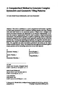
Figure 1. This schematic diagram shows the typical workflow for Digital Elevation Model (DEM) production described in this study.
5
5
Earth Surf. Dynam. Discuss., https://doi.org/10.5194/esurf-2018-53 Manuscript under review for journal Earth Surf. Dynam. Discussion started: 6 July 2018 c Author(s) 2018. CC BY 4.0 License.
2.1. Equipment The quality of image data collection can be improved by careful camera system selection, configuration, and image acquisition. The Camera system plays a vital role in effective resolution, signal-to-noise ratio, and distortion (Mosbrucker et al., 2017). For this work, low-cost, consumer-grade, ultra-compact and lightweight Nikon D5500
5
DSLR camera was used. A Digital Single Lens Reflex (DSLR) camera system includes a camera body and a lens. This camera has an Advanced Photo System type-C (APS-C) sensor (366.6 mm2) with no anti-aliasing filter and captures an image with an effective resolution of 24.2 Mega Pixels (MP). A DSLR camera provides flexibility in selecting different kinds of lenses and captures high-resolution images in raw (RAW) format. Images in raw format store more Red Green blue (RGB) pixel information than in Joint Photographic Experts Group (JPEG)
10
format. We used a zoom lens with a variable focal length of 18-55 mm and a 35 mm prime or fixed focal-length lens in this study. More comprehensive discussion of camera system consideration and configuration for SfM Photogrammetry work is found in Bedford (2017) and Mosbrucker et al. (2017).
2.2. Control target and local coordinate system
15
The dense point cloud generated by SfM is not scaled or oriented to real-world dimension. Therefore, registration to a known coordinate system (geographic or local) using Ground Control Points (GCPs) is required to reference and scale the model. GCP refers to a point with known coordinates (x, y, z). Incorporating GCPs in the SfM workflow is known to reduce systematic errors such as doming and dishing (Javernick et al., 2014; James and Robson, 2014) and permits a check on the accuracy of DEMs. At least three GCPs are required to generate a DEM
20
from a dense point cloud. For our study, we designed and built a new, portable control target (Figure 2). The triangle control target was made from 13 cm long craft sticks covered with textured plastic tape to protect it from shrinking and swelling in humid conditions (Figure 2). Each vertex served as a GCP. A set of three 12-bit coded markers were printed from Agisoft Photoscan software, laminated and attached at each vertex (Figure 2). The advantage of using coded
25
markers is that they can be automatically identified in Photoscan which minimises the time and reduces error. Goldstein et al., (2015) found that the number and the placement of GCPs affect the accuracy of SfM derived DEMs. In this work, our area of interest was small (