Email: 1goodidea,bubblegame,blues,[email protected]. AbstractâThis ... basic concept of. LINC is to convert the phase-and-amplitude-modulated signal ..... PSD [dB]. (a) Ideal case. (b)1+ÎG/G0=1dB, ÎÏ=10o, w/o calibre. (c)1+ÎG/G0=1dB, ...
A Sub-mW All-Digital Signal Component Separator with Branch Mismatch Compensation for OFDM LINC Transmitters Tsan-Wen Chen, Ping-Yuan Tsai, Jui-Yuan Yu, and Chen-Yi Lee Dept. of Electronics Engineering and Institute of Electronics, National Chiao-Tung University, Hsinchu, Taiwan, R.O.C. Email: {goodidea,bubblegame,blues,cylee}@si2lab.org
Abstract— This paper presents a sub-mW all-digital signal component separator (SCS) with a novel branch mismatch compensation scheme for OFDM LINC transmitters, including a phase calculator and a digital-control phase shifter (DCPS) pair. This chip is manufactured in 90nm standard CMOS process with active area 0.06mm2 . The DCPS can generate phase-modulated signal at IF 100MHz with 8-bit resolution and RMS error 9.33ps (0.34∘ ). The phase calculation can be operated with maximum 50MHz speed at 0.5V supply voltage, resulting in 73.88% power reduction, and the overall SCS power is only 949.5𝜇W. With the aid of this SCS, the branch mismatch compensation scheme provides 0.02dB gain and 0.15∘ phase fine-tune resolution. The system EVM with 64-QAM OFDM signals is -29.81dB, and the spectrum can pass the mask test of IEEE 802.11a.
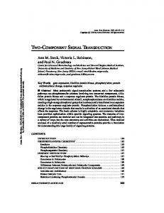
I. I NTRODUCTION Orthogonal frequency division multiplexing (OFDM) is a promising solution for high-data-rate wireless transmission in frequency selective channels. Due to the high peak-toaverage-power-ratio (PAPR) of the signals, the linear power amplifier (PA) requires to back off the operation point to avoid distortion, resulting in considerable efficiency degradation. Linear amplification by nonlinear components (LINC) [1] has been proposed to maintain the PA efficiency along with the good linearity. As shown in Fig. 1, the basic concept of LINC is to convert the phase-and-amplitude-modulated signal to two phase-modulated signals by a signal component separator (SCS) and then through two high-efficiency nonlinear PAs, such as class-D or E. Then the original signal can be reconstructed by combining these two amplified signals. Although LINC can improve the amplification efficiency, a low power and accurate SCS becomes another design challenge. To achieve high separation accuracy, digital implementation [2] is assumed to be the best choice. However, digital SCS requires four DACs, and the power consumption suffers from high operation frequency (more than 8x symbol rate) due to the nonlinear separation process [3]. Several analog designs are proposed to reduce the power consumption [4]–[6], but it is difficult to realize accurate mathematical functions and sensitive to PVT variations. Besides, those published chips still cost tens-milli-order power consumption which is a significant overhead for the transmitter. This work presents a sub-mW and This work was supported by MOEA of Taiwan, R.O.C., under Grant 98EC-17-A-03-S1-005.
Nonlinear PAs S C S
Fig. 1.
LINC schematic.
all-digital SCS design for LINC transmitters. Instead of four DACs, two digital-control phase shifters (DCPSs) are used to generate the phase-modulated signals. This chip can be globally operated at 0.5V to save lots of power dissipation. Another limitation in an LINC transmitter is the tight tolerance on the branch imbalance, resulting in unacceptable outof-band spectrum and signal quality [7]. Fortunately, digital mismatch calibration schemes have been proposed to detect the gain and phase mismatch information [8]. The phase mismatch can be compensated by DSP functions or adding delays on another branch. However, changing the magnitude before a nonlinear PA is useless since only the phase information can be recognized. Adding high-resolution gain adjustable capability to PA results in higher design complexity and efficiency loss. This work proposes a compensation scheme integrated in the SCS to balance both gain and phase mismatches, such that PA design complexity can be reduced. This paper is organized as follows. In section II, the SCS behaviors with the proposed mismatch compensation scheme are given. Then the chip implementation details are described in section III. Section IV shows the system simulation and experimental results, followed by the conclusion in section V. II. LINC SCS WITH M ISMATCH C OMPENSATION The transmitted signal can be generally expressed as } { 𝑆(𝑡) = Re (𝑆𝑖 (𝑡) + 𝑗𝑆𝑞 (𝑡))𝑒𝑗𝑤𝑐 𝑡 = 𝐴(𝑡) cos(𝑤𝑐 𝑡 + 𝜃(𝑡)) where the envelope 𝐴 (𝑡) =
√ 𝑆𝑖2 (𝑡) + 𝑆𝑞2 (𝑡),
and 𝜃(𝑡) is the phase given by 𝜃 (𝑡) = tan−1 (𝑆𝑞 (𝑡)/𝑆𝑖 (𝑡)) .
(1)
Proposed SCS S1 θ+φ1 S φ1 Amax
S1 φ2
θ
S2 θ-φ2
V2
φ1
V1
Gain comp.
S
θ
Si φ2
S2 θ-φ2
PM Phase Calculator
PM
Sˆ1 Sˆ2
(2)
𝜙1 (𝑡) = 𝜙2 (𝑡) = cos−1 (𝐴 (𝑡)/𝐴max ) .
(3)
Therefore, these two phase-modulated signals can be generated by two phase modulators (PMs). Considering the gain mismatch Δ𝐺 and phase mismatch Δ𝜙, the amplified signal 𝑆𝑜 (𝑡) becomes 𝑆𝑜 (𝑡) = 𝐺0 𝑆1 (𝑡 + 𝜙0 ) + (𝐺0 + Δ𝐺)𝑆2 (𝑡 + 𝜙0 + Δ𝜙)), where 𝐺0 and 𝜙0 are gain and phase delay of the PA and other front-end (FE) circuits. 𝑆𝑜 (𝑡) contains not only the desired signal 𝐺0 𝑆 (𝑡) but also other in-band and out-band noises [8]. Assuming the mismatch values can be detected accurately from the feedback loop by giving certain patterns [8], a SCS with mismatch compensation scheme shown in Fig. 3 is proposed to balance these mismatches. First, the phase mismatch can be compensated by adding a tunable delay chain to each branch, and set the delay difference of these two delay chains as 𝜙𝑐 = Δ𝜙, such that the phase delay can be balanced. For gain compensation, this work proposes to feedback the gain mismatch information to the phase calculator and to compensate the gain mismatch by giving the specified phases. The gain ratio of two branches denoted as 𝐺𝑐 = 1 + Δ𝐺/𝐺0 can be considered during the signal separation to satisfy the following quality: (4)
The vector representation of (4) is shown in Fig. 2(b). Define 𝑉1 = 𝐴𝑚𝑎𝑥 and 𝑉2 = 𝐴𝑚𝑎𝑥 𝐺𝑐 , then 𝜙1 (𝑡) and 𝜙2 (𝑡) can be derived from (2) and (4): 𝑉12 +4𝐴2 (𝑡)−𝑉22 ) 4𝐴(𝑡)𝑉1 2 2 2 𝑉 +4𝐴 (𝑡)−𝑉 cos−1 ( 2 4𝐴(𝑡)𝑉2 1 ).
𝜙1 (𝑡) = cos−1 ( 𝜙2 (𝑡) =
FE + PA
Sˆo
FE + PA
Gc = 1 + ΔG / G0 Fig. 3.
φc = Δφ
SCS with the proposed branch mismatch compensation scheme.
III. C HIP I MPLEMENTATION
𝑆1 (𝑡) = 0.5𝐴max cos (𝑤𝑐 𝑡 + 𝜃 (𝑡) + 𝜙1 (𝑡)), 𝑆2 (𝑡) = 0.5𝐴max cos (𝑤𝑐 𝑡 + 𝜃 (𝑡) − 𝜙2 (𝑡)),
𝑆1 (𝑡) + 𝐺𝑐 𝑆2 (𝑡) = 𝑆(𝑡)
G0δ (t + φ0 )
(G0 + ΔG )δ (t + φ0 + Δφ )
Vector representation of SCS (a)ideal case, (b)gain mismatch.
From Fig. 2(a), the signal 𝑆(𝑡) can be separated to two constant-envelope signals 𝑆1 (𝑡) and 𝑆2 (𝑡):
where
Sq
Phase comp .
(b) V1 = Amax , V2 = Amax(1+ΔG/G0 )
(a)
Fig. 2.
θ+φ1
(5)
Denote 𝑆ˆ1 (𝑡) and 𝑆ˆ2 (𝑡) as the signals after mismatch compensation, the amplified signal with the proposed compensation denoted as 𝑆ˆ𝑜 (𝑡) can be verified: 𝑆ˆ𝑜 (𝑡) = 𝐺0 𝑆ˆ1 (𝑡 + 𝜙0 ) + (𝐺0 + Δ𝐺)𝑆ˆ2 (𝑡 + 𝜙0 + Δ𝜙) = 𝐺0 [𝑆1 (𝑡 + 𝜙𝑐 + 𝜙0 ) + 𝐺𝑐 𝑆2 (𝑡 + 𝜙0 + Δ𝜙)] ′ = 𝐺0 𝑆(𝑡 + 𝜙0 ), which is the desired signal with a constant delay. Therefore, the branch mismatch effect can be eliminated by the proposed SCS without changing the FE or PA circuits.
Figure 4(a) presents the chip block diagram and signal paths. With the signal bandwidth 5MHz, the source signal from the baseband modem is 10x interpolated and quantized to 8bits in this work. So the phase calculator calculates the 8-bit phase codeword P1 and P1 for the PMs with 50MHz operation speed. Here a delay-line based DCPS is suggested to behave as not only a PM but also a phase compensation unit. Two mappers are used to transfer the phase codewords to the DCPS control codewords. With the detected gain and phase mismatch value, the phase calculator and the DCPS can provide the gain and phase compensation capability respectively. To achieve low power and accurate SCS, this chip is partitioned into two independent power domains with different supply voltages. The default domain uses 1.0V to interface with IO pads, and the DCPS pair also uses 1.0V to achieve accurate results. All DSP functions, including the phase calculator, codeword mappers, registers, and the controller, are operated with 0.5V supply voltage to save power consumption. A. DCPS Design Figure 4(b) shows the proposed DCPS design architecture. This DCPS design contains two-stage delay-lines with 9bits coarse-tune codeword C and 5bits fine-tune codeword F to achieve adequate dealy range and accuracy, and the delayline is based on power-of-two architecture to avoid complex codeword encoder. The digital control varactors (DCV) [9] is applied to the fine-tune stage to generate ps-level resolution by adding small capacitance loading, implying a ps-level phase compensation resolution can be achieved too. With the phase codeword P = 𝑘, the output delay of DCPS can be expressed by 𝑇0 + 𝑘𝑇𝑟𝑒𝑓 /256, 𝑘 = 0, 1, . . . , 255, where 𝑇0 is the constant delay and 𝑇𝑟𝑒𝑓 is the IF clock period. Denote the DCPS codewords corresponding to the delay 𝑇2𝜋 = 𝑇0 + 255𝑇𝑟𝑒𝑓 /256 as C(M) and F(M) , and the ratio of coarse-tune resolution and fine-tune resolution as 𝛽. To generate the desired phase 2𝑘𝜋/256, the mapper provides the DCPS coarse-tune codeword as ⌊ (M) ⌋ (6) C = C256 𝑘 , and the fine-tune codeword as ⌊( (M) ⌊ (M) ⌋) C 𝑘 C 𝑘 𝛽+ F= − 256 256
F(M) 𝑘 256
⌋
.
(7)
However, C(M) , F(M) , and 𝛽 are influenced by PVT conditions, so an automatic detection flow is embedded to detect
Si
0
Clock Manager 50MHz
P1
8
Phase Calculator
8
14
P2
8
0
1
0.5V domain
Mapper1
From OFDM Modem
Sq
Default domain
100MHz
IF Clk. 100MHz
14
C1, F1
256
S1
DCPS1
1 1
C[8]
C[0]
5
8
Mapper2
14
C2 , F2
DCPS2
F[4] 16
Const.
S2
F[0] 1
F[4] 16
Const.
F[0] 1 DCV
(b)
R_IN
8
8
10
10
V1
V2
Gc
φc1 φc 2 C(M), F(M) β
Register File
10
14
PVT REG
5
UP
Control
PD
DOWN
0.5V Domain
1.0V Domain
Clock
Digital code
C1
0
0 1
C(M) C(M) C(M)
C(M)
0 0
0
F1
0
0 0
0
0
1
F(M)
0 1
β
C2
0
0 0
0
0
0
0
1 1
1
F2
0
0 0
0
0
0
0
0 0
0
0
Control
Detect
(a)
Fig. 4.
C(M)
Detect
F(M)
Detect β
(c)
(a) Proposed SCS chip design with power domain partitions, (b) DCPS architecture, (c) Parameters detection flow and codeword settings.
these information for mapper before the normal operation. Taking the advantage of the same property in the dual DCPSs, only an additional phase detector (PD) is added to construct a delay-locked-loop (DLL). By the codeword setting as shown in Fig. 4(c) to the DLL, C(M) , F(M) , and 𝛽 can be detected and stored. Since the PVT is time-varying, this detection flow can be repeated before each transmission. B. Voltage Scaling and Hardware Optimization To apply the voltage scaling scheme in the standard-cellbased design procedure, the cell behavior and timing information under 0.5V supply voltage are simulated and re-calibrated, then the cell library after picking out the cells which can work normally is reconstructed. With the reconstructed 0.5V cell library, the proposed SCS design can be implemented by exploiting standard-cell-based design procedure. However, the transition duration under 0.5V is increased a lot, so complex computation can’t be implemented when the limited operation period. For the phase calculation of (1) and (5), the critical path is happened on the long-bit division. To apply the voltage scaling scheme, we use another expressions to avoid the division operations: 𝜃(𝑡) = tan−1 exp(log 𝑆𝑞 (𝑡) − log 𝑆𝑖 (𝑡)), 𝜙1 = cos−1 exp(log(𝑉12 + 4𝐴2 (𝑡) − 𝑉22 ) − log(4𝐴(𝑡)𝑉1 )), 𝜙2 = cos−1 exp(log(𝑉22 + 4𝐴2 (𝑡) − 𝑉12 ) − log(4𝐴(𝑡)𝑉2 )). Therefore, the division can be replaced by the logarithm table to meet 50MHz operation speed at 0.5V. Take a 8-bit calculation of 𝜃(𝑡) as an example, the simulated propagation delay is reduced from 22.49ns to 14.04ns within similar area. IV. S IMULATION AND E XPERIMENTAL R ESULTS The proposed SCS chip is fabricated in 90nm 1P9M CMOS standard process. The measurement instruments include a LeCroy 4000A oscilloscope and a current-meter with resolution of 100pA. And we use MATLAB to construct a system simulation platform including the RF component models. Figure 5 shows the measured output waveforms when 180∘ phase difference between two branches, and the measured
S1
skew
S2
Fig. 5.
Measured SCS output waveforms.
phase difference is 5.003ns which is close to the ideal value 5ns. With the constant delay 3.63ns, the coarse-tune and finetune stages of the DCPS can provide additional maximum delay 18.73ns and 0.127ns respectively. The average resolutions of each stage are 37.76ps and 4.21ps, and the measured RMS jitter is 8.57ps. After the detection of C(M) , F(M) , and 𝛽 automatically, Fig. 6 shows the measured DCPS output delay with different control codeword P, 8-bit resolution with RMS error 9.33ps (0.34∘ ) can be achieved. The measured result is consistent with the simulation except the larger constant delay because the IO pad delay is not considered during the simulation. The power consumption of the DCPS pair and PD is 912.9𝜇W at 100MHz IF frequency with 1V supply voltage. Cooperating with the detection scheme in [8], the proposed SCS can provide 0.02dB gain and 0.15∘ phase compensation resolution and allow maximum 1dB gain and 10∘ phase imbalance, which releases the PA design complexity. Fig. 7 shows the simulated system spectrum considering the branch mismatch effect, the spectrum without mismatch calibration is over the mask due to incomplete outphase signal cancellation. With the proposed SCS and mismatch compensation scheme, the spectrum can pass the 1/4 scaled 802.11a mask due to assumed 5MHz symbol rate in this work. And the system error vector magnitude (EVM) is -29.81dB which is less than the target specification -25dB. Figure 8 shows the micro chip photo with power domain notations, and the active area is only 0.06mm2 . The DSP blocks with 50MHz operation speed is reduced from 140.11𝜇W to 36.6𝜇W by scaling the supply voltage to 0.5V, resulting in
14 Default domain
13
0.5V domain
12
DCPS Pair+ PD+Clk. manager
Output Delay [ns]
11 10 9
Phase Calculator
150um
Control + Mapper+ Reg.
Other Testing Circuits
300um
8
450um
7 6
60um
5 170um
4 3 2
Simulation Measurement
1 0 0
Fig. 6.
32
64
96 128 160 Codeword P
192
224
450um
256
Fig. 8.
TABLE I C HIP S UMMARY AND C OMPARISON
The DCPS output delay with different codeword P.
0
Technology −10
PSD [dB]
−20
(b)
−30 (c)
−40 −50
(a) Ideal case (a)
o
(b)1+ΔG/G0=1dB, Δφ=10 , w/o calibre.
−60
o
(c)1+ΔG/G0=1dB, Δφ=10 , w calibre. Mask
−70 90
Fig. 7.
92.5
95
97.5 100 102.5 Frequency [MHz]
105
107.5
110
Chip photograph.
Design Strategy Supply Voltage Operation Frequency Power Signal Source EVM Mismatch Compensation Active Area (mm2 )
[4] 0.8um BiCMOS
[5] 0.35um CMOS
[6] 0.25um CMOS
Analog
Analog
Analog
5.0V 200MHz IF 100mW
N/A
5.0V 100MHz IF 80mW DQPSK OQPSK N/A
2.5V 20MHz Baseband 45mW 64QAM OFDM -37.6dB
This work 90nm CMOS All digital, Standard-cell 1.0V/0.5V 100MHz IF/ 50MHz DSP 0.95mW 64QAM OFDM -29.81dB
No
No
No
Yes
2.66 (*)
0.61 (*)
0.09
0.06
DQPSK
(*) die size
Output signal spectrum with branch mismatch effect.
ACKNOWLEDGMENT 73.88% power reduction. The chip summary and comparison table are shown in Table I. This work proposes an all-digital and standard-cell-based design. By using DCPS pair instead of DACs and scaling the supply voltage for DSP blocks, the overall chip consumes only 949.5𝜇W which is a significant improvement comparing to state-of-the-art solutions. With the advantages from both the technology scaling and hardware optimization, the active area is also the smallest. The EVM performance is worse than [6] because we further consider 8bit baseband quantization error and branch mismatch, but it is still acceptable for the demonstrator systems. V. C ONCLUSION An all-digital SCS is presented in this work. A branch mismatch compensation scheme is also integrated to release the PA design complexity. The proposed low-complexity DCPS pair with high resolution can generate phase-modulated signals accurately without DACs, and it also provides phase compensation capability. The power consumption of DSP circuits can be reduced by applying voltage scaling scheme. Therefore, a sub-mW and accurate LINC SCS can be achieved and applied to general OFDM systems to enhance amplification efficiency while maintaining similar link performance.
The authors would like to thank UMC for the University Shuttle Program in fabricating the test chip. R EFERENCES [1] D. C. Cox, “Linear amplification with nonlinear components,” IEEE Trans. Commun., vol. COM-22, no. 12, pp. 1942-1945, Dec. 1974. [2] S. A. Hetzel, A. Bateman, and J. P. McGeehan, “A LINC transmitter,” in Proc. IEEE Vehicular Technology Conf., St.Louis, MO, pp. 133-137, May 19-22, 1991. [3] L. Sundstrom, “Effects of reconstruction filters and sampling rate for a digital signal component separator on LINC transmitter performance,” Electron. Lett., vol. 31, no. 14, pp. 1124-1125, Jul. 1995. [4] B. Shi and L. Sundstrom, “A 200-MHz IF BiCMOS signal component separator for linear LINC transmitters,” IEEE J. of Solid-State Circuits, vol. 35, no. 7, pp. 987-993, Jul. 2000. [5] B. Shi and L. Sundstrom, “An IF CMOS signal component separator chip for LINC transmitters,” in Proc. IEEE Custum Integrated Circuits Conf. (CICC), pp. 49-52, May 2001. [6] L. Panseri, L. Romano, S. Levantino, C. Samori, A.L. Lacaita, “Lowpower signal component separator for a 64-QAM 802.11 LINC transmitter,” IEEE J. of Solid-State Circuits, vol. 43, no. 5, pp. 1274-1286, May 2008. [7] L. Romano, L. Panseri, C. Samori, and A. L. Lacaita, “Matching requirements in LINC transmitters for OFDM signals,” IEEE Trans. Circut Sys. I, vol. 53, No. 7, Jul. 2006. [8] X. Zhang, and L. E. Larson, “Gain and phase error-free LINC transmitter,” IEEE Trans. Veh. Technol., vol. 49, no. 5, pp. 1986-1994, Sep. 2000. [9] P.-L. Chen, C.-C. Chung, C.-Y. Lee, “A portable digitally controlled oscillator using novel varactors,” IEEE Trans. Circuit Sys. II, vol. 52, no. 5, pp. 233-237, May. 2005.