1988
IEEE TRANSACTIONS ON SYSTEMS, MAN, AND CYBERNETICS—PART B: CYBERNETICS, VOL. 34, NO. 5, OCTOBER 2004
A Subsumptive, Hierarchical, and Distributed Vision-Based Architecture for Smart Robotics Guilherme N. DeSouza, Member, IEEE, and Avinash C. Kak
Abstract—We present a distributed vision-based architecture for smart robotics that is composed of multiple control loops, each with a specialized level of competence. Our architecture is subsumptive and hierarchical, in the sense that each control loop can add to the competence level of the loops below, and in the sense that the loops can present a coarse-to-fine gradation with respect to vision sensing. At the coarsest level, the processing of sensory information enables a robot to become aware of the approximate location of an object in its field of view. On the other hand, at the finest end, the processing of stereo information enables a robot to determine more precisely the position and orientation of an object in the coordinate frame of the robot. The processing in each module of the control loops is completely independent and it can be performed at its own rate. A control Arbitrator ranks the results of each loop according to certain confidence indices, which are derived solely from the sensory information. This architecture has clear advantages regarding overall performance of the system, which is not affected by the “slowest link,” and regarding fault tolerance, since faults in one module does not affect the other modules. At this time we are able to demonstrate the utility of the architecture for stereoscopic visual servoing. The architecture has also been applied to mobile robot navigation and can easily be extended to tasks such as “assembly-on-the-fly.” Index Terms—Assembly-on-the-fly, automation, computer vision, distributed architectures, robotics, vision-based architecture, visual servoing.
I. INTRODUCTION A. Architectures for Robotic Systems
I
N THE past fifteen years, since the work of [1]–[3], researchers in robotic systems have begun to realize the importance of decomposing a vertically-sliced, single-threaded control architecture into smaller, horizontal, and independent units. These new multilayered architectures became widely accepted [4]–[6], and since then much work has been carried out to refine the output from each layer and to combine these outputs at the highest level of the architecture [3], [5], [7]–[9], [10]. Basically, two divergent streams of research appeared: the top-down control and the bottom-up control. In a strictly hierarchical architecture, or top-down control, all input parameters must be taken into consideration before a command output can be decided. This decision-making process runs Manuscript received September 22, 2003; revised March 12, 2004. This work was supported by the Advanced Manufacturing Technology Development, Ford Motor Company. This paper was recommended by Associate Editor F. Hoffmann. G. N. DeSouza is with the School of Electrical, Electronic, and Computer Engineering, University of Western Australia, Crawley 6009, Australia (e-mail:
[email protected]). A. C. Kak is with the School of Electrical and Computer Engineering, Purdue University, West Lafayette, IN 47907 USA (e-mail:
[email protected]). Digital Object Identifier 10.1109/TSMCB.2004.831768
from the top-layer tasks down to the bottom-layer tasks. Each task in a higher layer decides which task in the lower layer will execute subsequently. Only one task is active at a given time and the whole process can fail if the appropriate tasks are not selected by the top layers. Besides, when the execution of a command does not succeed, a complete cycle starting from the very top has to be re-evaluated, so that the higher-layer tasks can participate in the decision-making process again [11]. On the other extreme of the spectrum of multilayered architectures we find the bottom-up approaches, including the subsumption and behavior-based architectures. In these implementations, all behaviors are active all the time, and it is not uncommon for the more competent behaviors to completely subsume the function of the behaviors that are less competent. This calls for an interaction of all behaviors during the decision process. In fact, the interaction of behavior itself can be seen as a behavior. However, the modeling of such interaction is a nontrivial problem and in a large, real-life scenario this problem can become intractable. That difficulty led some researchers to recently claim that “the strict computational behaviorist position for the modeling of intelligence does not scale to human-like problems and performance” [12]. Other researchers tried to minimize this problem by layering reactive behaviors onto deliberative behaviors (or components) and by constraining the contexts in which they are active [8]. Yet, in another attempt to reduce the interaction between behaviors, Rosenblatt proposed a centralized arbitration of votes from independent decision-making processes [6]. In this model, self-contained behaviors are made simple enough so they can be implemented in a very straightforward way. Moreover, a behavior is not aware of the command outputs from other behaviors, and therefore, the burden of evaluating each output and to combine them in a more appropriate way is transfered to the arbiter (or voting scheme). The arbiter has to determine what command, or combination of commands [13], should be issued to the robot. Another frequent problem in behavior-based architectures is that outputs from all behaviors must be available at all times so that a decision regarding the next state of the system can be made. That is, if for some reason a behavior fails to provide its output, the decision-making process may be compromised, and an undesired state of the system may be reached. B. Vision-Based Robotics and Automation While researchers were debating what architecture was best for the development of vision-based robotic systems, the actual application of such systems to automation was limited
1083-4419/04$20.00 © 2004 IEEE
DESOUZA AND KAK: SUBSUMPTIVE, HIERARCHICAL, AND DISTRIBUTED VISION-BASED
Fig. 1. Example of assembly cells in the automotive industry.
to tasks that could be naturally adapted to suit robotic constraints. Welding of fixed targets, painting of large targets, and bin-picking of objects resting on conveyor belts that moved at constant speed were determined to be examples of manufacturing tasks for which robotic systems were perfectly suited. If the task to be automated required many changes in the environment, or the way the task was carried out, usually only simple parts of the task could be automated [14]. This picture is dramatically changing due the increase in computer processing power and the low prices of cameras, image grabbers, CPUs, and computer memory. These developments make it possible to address the kind of automation problems illustrated by the example shown in Fig. 1. This example, of great relevance to automobile industry, requires a wheel to be mounted onto a hub on a car chassis that is hanging by four chains attached to a moving track. The car swings in almost every direction, and its position in three–dimensional (3-D) space can only be estimated within some uncertainty. Nevertheless, for this task to be successfully automated the holes in the wheel must be precisely aligned with the lugs in the hub, which are only a few millimeters more narrow than the holes. In order to satisfy these tight constraints, a visual servoing system must run at its highest possible rate. That means that the time spent in image processing and all other intrinsic delays must be minimized. One way of reducing these delays is by separating the processing into modules and running the modules in parallel. In this case, the total delay of the system becomes the delay of one module, rather than the summation of all delays. Another important requirement regarding the automation of manufacturing tasks is safety and availability of the system. An effective autonomous system must present fault tolerance. That means that, in the presence of temporary or permanent failures of its parts, the system must continue to provide valid control outputs—outputs that allow the robot to perform its task or that move the robot into safe states, where the robot and the assembly parts cannot be damaged. As it is the case for many other computer-based control systems, a fault tolerant system must be designed with enough redundancy and independence in its different modules so that, in the case of failures, the overall availability of the system is not affected. Therefore, by decoupling and paralyzing the execution of modules in the control loop, not only are the delays minimized such that the vision constraints can be satisfied, but also the system can be made fault tolerant. In this case, independent modules can run in parallel and can subsume or replicate the functionality of other modules, improving the availability of the system.
1989
In this paper, we present such a control software architecture for visual servoing. This architecture, which is depicted in Fig. 2 and will be explained in detail in the next few sections, is composed of independent and distributed control loops that concurrently provide control for the robotic system. As we will demonstrate, our vision-based architecture is efficient, flexible, and it satisfies all the requirements of today’s automation processes, including fault-tolerance. II. NEW SOFTWARE ARCHITECTURE The resources necessary to implement distributed architectures (over a computer network) have been available for a long time and have even become part of most operating systems today [15]. However, many of the early implementations of robotic control architectures did not take advantage of these resources [1]–[3], [5]–[10], [16]. Consequently, most of these implementations lack modularity, portability, encapsulation, and parallelism (distributed processing), trades that are essential for achieving speed, fault tolerance, availability, etc. In [17], we introduced the basic software infrastructure for the visual servoing architecture presented in this paper. This infrastructure combines concepts such as threads, processes, pipes, and software wrappers in order to provide a portable and modular environment for experimenting with robotic control architectures. The infrastructure allows a system’s resources (motors, cameras, etc.) to be accessed concurrently by the different application modules1 operating in a distributed network of processors. All those considerations—use of pipes, message structure, and atomic message passing—provide fault-tolerance, flexibility, efficiency, portability, modularity, and encapsulation to any robotic system. With regard to message passing needed for a distributed architecture, not much has been done previously in the domain of robotic systems. Of course, there are general purpose tools available today for the design of distributed software systems—Common Object Request Broker Architecture (CORBA) by the Object Management Group2 being the best known of these—but they are not suitable for implementing real-time vision-based control loops.3 Despite the fact that our visual servoing architecture could sit on top of any package that provides inter-process communication, distributed processing, etc., the use of a communication middleware such as CORBA cannot be as efficient as a client/server infrastructure mounted directly on top of the operating system and the TCP/IP protocol. A. Control Software Architecture Now, we will discuss how the various elements of the software infrastructure presented in [17] can be combined to create a control software architecture that can be applied in any visual servoing system. The next section presents one specific 1A module in our architecture is a program that can be executed on a standalone basis. As we explain in Section V, control performance can be maximized by implementing the modules in different computers. 2See http://www.corba.org. 3Some ostensibly “real-time” implementations of CORBA are not real-time in the sense demanded in vision-based robotic control for manufacturing applications.
1990
IEEE TRANSACTIONS ON SYSTEMS, MAN, AND CYBERNETICS—PART B: CYBERNETICS, VOL. 34, NO. 5, OCTOBER 2004
Fig. 2. Generic organization of control loops used in our visual servoing architecture.
instance of this software architecture that was developed for the Ford Line Tracking project. Another application of the architecture—for mobile robot navigation—can be found in [18]. 1) Multiloop Control Architecture: For the reasons that we have already mentioned—fault tolerance, redundancy, availability, etc.—our architecture for visual servoing systems is composed of a stack of independent, redundant control loops. In Fig. 2 we depict such structure. The idea behind this structure is to create autonomous loops that can subsume each other and/or compete for the control of the robot. These loops are composed of different sets of modules, each of which may implement one of the several possible approaches for visual servoing: image-based look-and-move, position-based look-and-move, etc. [14]. Also, for reasons involving redundancy, fault tolerance, etc., the modules in one control loop may implement the exact same approach as the modules in another control loop. The differences in such cases can be, e.g., the cameras that different modules use to sense the robot position. These cameras could be oriented and positioned in various ways to minimize occlusions. Another difference between similar loops can be in their degrees of competence, that is, the level of detail and accuracy the control is performed. The modules in a particular control loop can be implemented only to provide a safe state for the system, and in that case, they may realize a much simpler visual servoing approach (e.g., servoing in XY space only; obstacle avoidance; etc.). 2) Independence of the Control Loops: As it should be clear now, one may draw parallels between the control loops in our architecture and the behaviors in a subsumptive, behavior-based architecture. In both cases, the task performed by a certain loop (or a behavior) can be subsumed by another, more complex loop
(or behavior). However, as we mentioned before, one of the most important aspects of our architecture is the independence of the visual-servoing loops. Therefore, unlike other subsumptive architectures where the subsumption of one behavior by a more competent one requires an intricate exchange of context and information between behaviors, in our system two loops never communicate with each other. Each control loop performs in a completely independent fashion. In fact, even the coordinate systems and the space in which the error functions are calculate may be different, as Fig. 2 illustrates. The modules in each control loop send concurrent commands to the robot through a module called Arbitrator. It is the Arbitrator that decides which loop or loops have control of the robot at any given moment. This decision is based on criteria imposed mainly by the application. For example, in the manufacturing case there may be a loop that is regarded as more important than the others: e.g., a loop that actually controls the assembly versus loops that take the robot to the initial/safe position. This loop has a higher priority and whenever it can track the part to be assembled—its cameras are not occluded, the image processing algorithm is running correctly, etc.—the loop has Arbitrator-granted control over the robot. As we explain in [18], for the case of the mobile robot, a path planner must indicate which loop has the highest priority at each moment. This decision depends upon the current navigation mode of the mobile robot: hallway following, person following, tracking, and servoing with respect to an object in the environment, etc. Also, the decision regarding which loop, or loops, are in control can be based upon how fast each loop sends commands to the Arbitrator. A loop that becomes slow in sending command
DESOUZA AND KAK: SUBSUMPTIVE, HIERARCHICAL, AND DISTRIBUTED VISION-BASED
Fig. 3. Image processing and communication threads in the image feature module referred in Fig. 2.
updates may be considered faulty by the Arbitrator and therefore, should be ignored. Finally, each control loop decides whether its vision module has none, partial, or complete sight of the target, and whether its image processing algorithms are running correctly. This fact is indicated by a confidence index which is assigned to the control loop command sent to the Arbitrator. Based on the confidence index, the Arbitrator can also decide if the control of the robot should be transferred to another loop. 3) Decoupling Application and Communication Tasks: Unfortunately, one aspect of the communication between modules has a more conceptual consequence. One of the reasons to encapsulate tasks into modules and distribute the modules over a network of interconnected computers is to provide independence between the tasks. This way, it becomes easy to design modules that can be replicated or have their tasks subsumed by other modules in case of failure. That is, modules that can be replaced by redundant or more generic ones. However, if a module happens to waste time or possibly block trying to communicate with a slower or faulty module, the whole idea of having the modules independent and running at their fastest possible rates is violated. In order to solve this problem, we designed every module as composed of at least two threads. The first thread is the application thread. It only performs the application task for which that module was created: e.g., the imaging processing task in the Image Feature Extraction module (Fig. 2). The second thread is the communication thread and it implements the client or server side of the communication with the other modules: for the same example, the communication with the Pose Estimation module in Fig. 2. These two threads run asynchronously, but they share information that must be produced (written) and consumed (read) in an organized way using a nonblocking sharedmemory access algorithm. For example, the two threads in the Image Feature Extraction module that we mentioned above can be visualized as shown in Fig. 3. The image processing thread (GotFrame) is responsible for extracting image features of the tracked object and for passing the pixel coordinates of these features to the Pose Estimation module. That is done through the communication thread (ProcessedFrame). GotFrame writes the coordinate values in a data structure that can be accessed (shared) by
1991
both threads, while ProcessedFrame reads this information and communicates with the Pose Estimation module. Since GotFrame may write new information while ProcessedFrame may still be reading the previous one, a locking of the data must be set before the write operation. The locking mechanism is a single-version two-phase locking algorithm and it consists of two locking variables, or members, of a single data structure. These variables can be reset (or set) by the producer of the information, while they can be set (or reset, respectively) by the consumer of the information. The first locking variable is called “request” and the second is called “written.” The producer of the information, GotFrame, checks constantly if the consumer, ProcessedFrame, requested the information—by checking the locking variable request (Fig. 3). If there is a request pending, the data is written to the shared memory, the written locking variable is set, and the request locking variable is reset. On the other side, ProcessedFrame sets the request variable whenever it needs the information, and it awaits for the data to be written. Once the data is available (indicated by the status of written), ProcessedFrame transmits the data, resets written, and initiates a new loop (sets request and waits for a new value to be written). This mechanism allows GotFrame to run as fast as possible—without blocking—and provides ProcessedFrame with the latest information extracted from the image. At the same time, ProcessedFrame can take as long as necessary to pass the information forward, or even timeout and start sending the information to another module that replaces the next module in the loop (in case of failure of that module). Another subtle but very important advantage of this mechanism is in the design of each module. Since the performance of each module does not depend on other module’s timings or delays, each design can be done separately. For example, to improve the performance of the visual tracking of a target object, GotFrame must be designed with a search window—a subwindow of the image plane where the object is expected to be found in the next frame. The size of this search window is greatly affected by the time GotFrame takes to process an image. If the performance of GotFrame were dependent upon the timings and delays of ProcessedFrame, it would become virtually impossible to design GotFrame. III. IMPLEMENTED APPROACHES TO VISUAL-SERVOING As explained in [14] and [19], a control system using visual-sensory feedback loops usually falls into one of the following categories: position-based look-and-move, position-based servo, image-based look-and-move, image-based servo, and various hybrid combinations. These categories, or approaches to visual servoing, are derived from choices made regarding two criteria: the coordinate space of the error function and the hierarchical structure of the control system. In this section, we will present the implementation details of two of these approaches chosen for our system. For simplicity of design and because the Kawasaki PC-Controller used with our UX120 robot provides a set of commands to control velocity and position of the end-effector in cartesian space, we decided that our system should fall in the
1992
IEEE TRANSACTIONS ON SYSTEMS, MAN, AND CYBERNETICS—PART B: CYBERNETICS, VOL. 34, NO. 5, OCTOBER 2004
look-and-move category.4 As for the second criterion, we will discuss the implementation of both approaches: image-based and position-based. As we will explain next, despite the fact that the position-based approach requires camera calibration, hand-eye calibration, and the calculation of the robot inverse kinematics, in our method it leads to a simpler control plant. On the other hand, while the image-based approach eliminates the errors from camera and hand-eye calibration, it requires a linear approximation of a nonlinear and highly coupled control plant. A. Notations 1) Homogeneous Vectors and Transformations: Unless otherwise specified, we will always assume a total of six different coordinate frames to represent points (vectors) in space. Each of these coordinate frames is attached to one of six different reference points or origins in our system. An origin may be indicated by the letters: B, E, W, O, L, and R; corresponding, respectively, to the origins at: the robot Base; the robot End-effector; the World; the Tracked Object; Left-camera; and Right-camera. In the remainder of this paper, we will follow the Denavit-Hartenberg (D-H) notation [20]. Also, in this notation, a homogeneous transformation matrix (HTM) is a 4 4 matrix that relates a homogeneous vector represented in one coordinate frame with its representation in terms of another coordinate frame. The superscript before the letter stands for the new frame the vector indicates is to be converted into, and the subscript after the the frame in which the vector was originally represented. For exis the HTM that transforms a 4 1 homogeneous ample, vector from the World coordinate frame into the Base coordi, and it nate frame. The inverse of this matrix is denoted by represents the transformation of a vector in the Base coordinate frame into the World coordinate frame. The same notation is apis plied for the rotational part of the HTMs. For example, the rotation of a vector from the World frame into the Base co. ordinate frame. The inverse of this matrix is denoted by In contrast, a vector is expressed in homogeneous coordinate form and is given by
(1)
where denotes one of the reference frames listed above (Base, End-effector, etc.). is composed of a rotational part and a transAn HTM lational part
as follows: (2)
that points to the The translation part is simply a vector is origin of the coordinate frame. The inverse of a HTM and can be obtained by the expression denoted by (3) 4Most of the systems implemented and reported in the literature fall in this same category and for these same reasons [14]
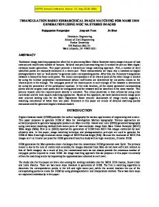
Fig. 4. Three model features of the target object and the coordinate frame defined by them.
where the superscript denotes the transpose of a vector or matrix.5 2) Target Object Coordinate Frame: In order to servo the robot with respect to a target object, the system needs to locate and track the object in the image sequence. There are many ways to do that, ranging from appearance-based methods to the use of detailed computer aided design (CAD) models of the target object. However, most methods degrade quickly with the use of extra cameras or the increase in the level of detail and number of features in the model. In [22] for example, a CAD model is employed and good results are reported, but the authors report a reduction of the system performance from 25 fps to as low as 14 fps due to the use of multiple cameras—not to mention that the system requires manual initialization. An advantage of a distributed, modular, and fault-tolerant architecture as we propose here is to allow for the deployment of several redundant algorithms running on multiple computers at the same time, which also allows for an experimentation with computer-intensive tracking algorithm. In particular, because of distributed processing, the current implementation of our system can process almost 140 fps, derived from five cameras, with virtually no limit for these numbers. Also, besides the geometric-based method reported here and in [23], we have developed other computer-intensive approaches for image tracking such as using Active Appearance Models (AAM) [24]. For the modules of the system that processes stereo images at frame rate (2 30 fps), we implemented an effective geometric-based method to determine the object coordinate frame. This method uses only three points and the cross-product among them (Fig. 4). The method relies on finding three particular circular features in the left and right images. Based on some unmistakable characteristic of these feature points—in our case, their size and relative pose in the model—our stereo algorithm can obtain the correspondence between these points in the left and right images instantaneously. Once the correspondence is known, all that is left to be done is the 3-D reconstruction of these points, which is explained in details in [23]. This method is very simple, fast, and accurate: in [23] we reported the calculation of the target pose with an uncertainty of only 2.4 mm. 5Since any rotation matrix can be represented by quaternions, and vice versa [21], our system stores and manipulates HTMs in their quaternion forms.
DESOUZA AND KAK: SUBSUMPTIVE, HIERARCHICAL, AND DISTRIBUTED VISION-BASED
1993
in Fig. 2. This matrix that will represent the reference signal HTM can be arbitrarily chosen as, for example
(5)
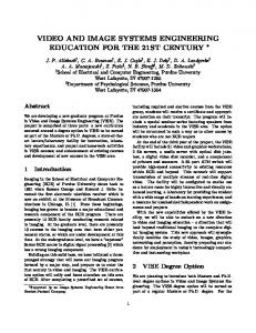
Fig. 5. Alignment between object and end-effector coordinate frames. The circular features can be used to determine the actual pose of the engine cover.
In this case, was chosen so that the axis and the axis have the same direction and orientation, while the other two pairs of axes, and have the same orientation, but they point in opposite directions. Also, the origins of each frame are apart from each other by meters along the direction. Given the above and , the error function can be defined as (6)
B. Control Law The task of a visual servoing system is to perform the positioning of the robot’s end-effector with respect to a target object while keeping track of the error in this positioning. But before we can define a control law that realizes this task, we must first formally define such task. This definition depends on the approach used—position-based or image-based—and it will be presented in the next two subsections. 1) Position-Based Visual Servoing: Definition 1: A positioning task for a position-based visual , where servoing is represented by a function is the number of degrees of freedom. This function is called the kinematics error function and it maps the task space —the set of all possible positions and orientations of the end-effector —into an error vector belonging to . A positioning task is . fulfilled when There can be many variations in the design and implementation of a visual servoing system. For example, depending on the application, the task space may be constrained by different numbers of degrees-of-freedom (DOF): three translational DOF [25], [26]; or three rotational [27]–[29]; or two translational and one rotational [30]; etc. Since in our system we want to control the robot’s end-effector so that its coordinate frame is aligned with respect to the object’s coordinate frame for any pose the object, we assume (Fig. 5). Given the definition above, we can now determine the control law for our first choice of visual servoing: position-based. One way of looking at the problem of aligning the two coordinate frames in space is by defining a transformation matrix that relates the end-effector’s kinematics, that is, the homoge, and the object’s pose, given neous transformation matrix . In other words by, say,
Since in a visual servoing system the sensory information is provided by cameras, this error function can be calculated by attaching a pair of stereo cameras on the robot end-effector. These stereo cameras can directly measure the position of the object . However, since the camwith respect to the end-effector, eras’ coordinate frames are not defined at the same position and with the same orientation as the end-effector’s coordinate frame, must be calculated in terms of two other HTMs. The first , where HTM is referred to as the hand-eye transformation, stands for or —the right and left cameras, respectively—and it is obtained through a hand-eye calibration (which we solve in , is the pose of the object with [31], [32]). The second HTM, respect to the cameras, which is obtained using 3-D reconstruction of object features (points in the object coordinate frame) and the camera calibration matrices (left and right). These features are used to determine the 3-D pose of the object’s coordinate frame, as explained earlier in this section. Given these matrices, (6) can now be written as (7) One important observation must be made regarding the difference operator in the last equations. Since we expressed the error function as the difference between two HTMs, and the arithmetic difference of such two matrices would not have a physical interpretation, one must define this operation in the correct manner. For HTMs, the difference or distance between two coordinate frames—in this case the end-effector actual poand the end-effector desired position —is the sition direct transformation from the second coordinate frame into the first coordinate frame. In other words, the difference operation in (6) must be in fact expressed as
That is (4) or is the pose of the end-effector ( in Definition 1 where above) and it can be regarded as the actual pose of the end-effector with respect to the object coordinate frame. Next, in order to define an error function and subsequently to define a control law, we need a constant homogeneous transformation
(8) In words: the HTM representing the coordinate frame of the end-effector at its desired position with respect to its coordinate frame at the end-effector’s actual position .
1994
IEEE TRANSACTIONS ON SYSTEMS, MAN, AND CYBERNETICS—PART B: CYBERNETICS, VOL. 34, NO. 5, OCTOBER 2004
Finally, our control law can be defined as a simple proportional control (9) Once again, the arithmetic multiplication of an HTM by a constant would result in a meaningless matrix in terms of the rotation and translation necessary to reach the desired position , we interpret of the end-effector. In this case, since this multiplication as a transformation that moves only a fraction of the rotational and the translational components specified by . In order to calculate the fraction of the rotation, we coninto its quaternion representation , and then we vert , while keeping the direction multiply the rotation angle by of rotation . As for the translation part, we simply multiply it . by 2) Image-Based Visual Servoing: As we have shown in the previous discussion, the position-based approach involves, among other things: a) determining the 3-D pose of the object using image features extracted from a pair of stereo images; and b) deriving the end-effector’s 6 degrees of freedom, XYZOAT, . While the first step infrom the error function volves 3-D reconstruction and therefore it requires camera and hand-eye calibrations, the second step involves the solution of the robot inverse kinematics. That is, the solution of a nonlinear system of equations, using sines, cosines, arc-tangents, etc. The accuracy of the results from either steps is highly affected by numerical errors and by noise in the images, which is not desirable. Therefore, a second way of looking at the alignment problem of end-effector and target object is commonly used. In this second approach, image-based approach, we derive an image error function directly in terms of the pixel coordinates of the object features—as opposed to spatial coordinates. Definition 2: A positioning task for an image-based visual servoing is represented by an image error function . Indirectly, this function maps the task space —the set of all possible positions and orientations of the end-effector s—into an image feature error vector belonging . to . A positioning task is fulfilled when In order to do that, since it is not always possible to calculate the function [33], [14], we must assume that there exists such a function relating the XYZOAT coordinates of the end-effector with pixel coordinates of the object features as they are seen by the cameras attached to the end-effector
(10)
are the image coordinates of each feawhere ture on the left (L) and right (R) image planes. And is the mapping function that we want to find. This function, although unknown, can be piece-wised linearized by its first-order term in the Taylor series
(11)
where is the Jacobian matrix. And as we have just mentioned, the error function now is defined directly in terms of pixel coor. That is dinates and the pseudo inverse of (12) which can be approximated by (13) Since this linear approximation is only accurate in a small vicinity of the 3-D region for which it is calculated, we must constantly recalculate the Jacobian matrix . This process is done by using the following updating equation: (14) Finally, the control law for the image-based approach can be defined as a simple proportional control (15) which is approximated by (16) is the pixel coordinates of the object features as seen where by the cameras when the end-effector is at the desired position and orientation. 3) Advantages/Disadvantages of Both Approaches: As we mentioned earlier, the position-based approach to visual servoing requires camera and hand-eye calibrations (or head-eye calibration for the case of the mobile robot stereo head). It also requires the calculation of the robot inverse kinematics in order to obtain the end-effector’s pose in terms of XYZOAT coordinates. While these procedures may introduce errors in the final positioning of the end-effector, these errors can be minimized by devising an accurate calibration procedure. In [31], we presented a fast and accurate method developed for hand-eye calibration (and in [32] for head-eye calibration for the case of mobile robots). This method combined with a camera calibration algorithm derived from [34] provided us with a 3-D reconstruction algorithm that can estimate points in space with error
DESOUZA AND KAK: SUBSUMPTIVE, HIERARCHICAL, AND DISTRIBUTED VISION-BASED
smaller than 1 mm in average for the Kawasaki robot (and 3 mm for the mobile robot stereo head). On the other side of the coin, it is well-known that the simple control law that we used in the image-based approach does not always converge [35]. Moreover, the Jacobian matrix in this approach may not always be invertible and the control law becomes unstable [14]. Therefore, a better implementation of the image-based approach must be used in the future. However, in spite of all the potential advantages and disadvantages of each approach, our goal here is not to advocate the use of one over the other. Instead, we mentioned and implemented both approaches only to stress the fact that the software architecture presented works independently of what approach is chosen. IV. APPLICATION OF THE SOFTWARE ARCHITECTURE FOR LINE TRACKING Automatic tracking of objects using computer vision will play an important role in further automation of vehicle assembly lines. Such automatic tracking will permit robots to carry out assembly operations without stopping the line, which moves at an average speed of 4.4 in./s, with instant velocities ranging from 1 to 10 in./s and accelerations of at least 0.49 in./s . Still, a typical assembly task may require an accuracy of th or even nd of an inch—which is equivalent to the distance traversed in about 7 ms by a vehicle in the assembly line moving at average speed. For the Line Tracking project, we have implemented a three-loop approach to visual servoing. Ceiling mounted cameras keep track of a vehicle on a global basis. As far as these cameras are concerned, a vehicle is a large blob that needs to be segmented out from the background using color, texture, and motion cues. As a vehicle gets sufficiently close to an assembly station, the control function is taken over by the stereo cameras mounted on the robot end-effector. This control is in 3-D and in real-time, meaning that all the 3-D pose parameters of the vehicle are calculated at as close to the frame rate as possible. We refer to the control loop accomplished with the ceiling-mounted cameras as Coarse Control and to the control loop achieved by the robot-mounted cameras as Fine Control. To demonstrate the property of fault tolerance of our architecture, the system was implemented using one Coarse Control loop and two redundant Fine Control loops as depicted in Fig. 6. A. Fine Control The design of the tracking and control algorithms for Fine Control is critically dependent on factors such as the following: 1) time to process enough visual cues in order to obtain a sufficiently accurate 3-D-Pose Estimation of the target; 2) time it takes to compute the new coordinates of the vehicle; 3) time it takes to predict the future motion of the vehicle based on its current coordinates, its previous coordinates, the noise in the system, the dynamics of the vehicle, and the dynamics of the line; 4) control law used for visual servoing; etc.
1995
Fig. 6. Architecture for the Line Tracking project consisting of multiple Fine Controls, Coarse Control, and Arbitrator.
We believe that all these issues are addressed by our distributed, hierarchical, subsumptive architecture. For example, the success of a factory-deployable fine-control scheme depends to a great degree on the magnitude of the control delays [36]. By distributing modules among different computers in the network, we assign all the computational resources of a computer to a single module, allowing it to perform at its fastest possible rate. Also, by designing the modules in a completely independent and self-contained manner, we can explore different approaches to visual servoing at the same time. Without affecting the implementation of each control loop, better camera and hand-eye calibration algorithms can be explored in order to improve the performance of a position-based approach, while new Jacobian matrix update methods can be tested for an image-based approach. Finally, by paralyzing the control loops and directing the output of each loop into the Arbitrator, we allow the modules to subsume the functionality of others. As it is the case between the Fine Control and the Coarse Control. The Fine Control block in Fig. 6 above is in fact a collection of different modules. In reference to the diagram shown in Fig. 2, the Fine Control corresponds to almost an entire loop, starting at the cameras (grabbing) and ending at the control Arbitrator. As pointed out before, we implemented two versions of the Fine Control. The first one uses a position-based approach, which requires the camera and head-eye calibration, [31], [32]. The second version uses an image-based approach using the Jacobian matrix update rule discussed in Section III-B2. That implies that for the position-based approach, the feature extraction block, the Pose Estimation block, and the Cartesian Control Law block (refer to Fig. 2) are all included in what we call here the first version of the Fine Control. On the other hand, for the image-based approach, the same feature extraction block was linked directly to the Feature Space Control Law block to form the second version of the Fine Control. In what follows, we will present the generic architecture of the Fine Control, which applies almost indistinctly for both versions. We will point out the differences when necessary. 1) Internal Architecture of the Fine Control: As Fig. 7 depicts, the Fine Control is composed of two modules. The first module implements the feature extraction block as we mentioned briefly in II.A3. The only difference here is that, since the
1996
IEEE TRANSACTIONS ON SYSTEMS, MAN, AND CYBERNETICS—PART B: CYBERNETICS, VOL. 34, NO. 5, OCTOBER 2004
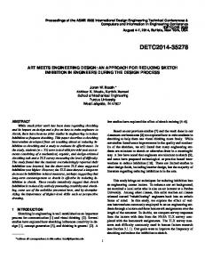
Fig. 8. Image processing performed by the Feature Extraction Module of the Fine Control. (a) The left image and (b) is the right image.
Fig. 7.
Composition of the Fine Controller.
Fine Control must servo the robot in all six degrees of freedom, we have two image processing threads: Left GotFrame and Right GotFrame, for the left and right cameras respectively. The second module encompasses one or two blocks following the arrows in Fig. 2, depending on the version of the Fine Control. For the version using image-based approach, the second module includes only the Feature Space Control Law block, while for the position-based approach it includes the Pose Estimation and the Cartesian Control Law blocks. In either cases, we call this the Servo Control Module. The Servo Control Module provides XYZOAT coordinates of the end-effector, which are transmitted to the Control Arbitrator. Also, the two modules of the Fine Control communicate with each other through a set of pipes encapsulated inside a wrapper (as discussed in [17].) This communication through the wrapper is represented here by the circle and arrows in Fig. 7. One important observation regarding the construction of these modules is that because of the concept of modularity and encapsulation discussed in [17] (e.g., use of wrappers), many of the threads and processes inside the Servo Control Module are applied to both versions of the Fine Control (image-based
or position-based). Besides all the advantages already pointed out, this characteristic of our software infrastructure also saves us time during system development. a) Feature Extraction Module: The Feature Extraction module is the same for both versions of the Fine Control (position-based and image-based). In either cases, it is composed of three threads: LeftGotFrame, RightGotFrame, and ProcessedFrame. LeftGotFrame and RightGotFrame are identical threads (almost identical source codes) whose basic algorithm is to search for three circular features and determine the pixel coordinates of their center points, [23]. In order to find these center points, GotFrame resorts to a model-based tracking algorithm where the model of the engine used describes the position and size of three predefined circular coordinates of features. During the online tracking, the each center and the apparent size of the circles are used to define a search window where the circle will be searched for in the next frame (see Fig. 8). This method allows the algorithm to adapt to different positions of the camera with respect to the target, that is, to adapt to different sizes of the circles in the image plane. At the end of the processing, the two modules write the left and right pixel coordinates of the circular features in a shared memory, using the mechanism discussed in Section II-A3. Also discussed in that section is the behavior of ProcessedFrame, which reads the information from the shared memory and passes it on to the next module: Servo Control Module. b) Servo Control Module: The Servo Control module is formed by three threads or processes. While two of these processes, VisualServo Communicator and Arbitrator Communicator, are the same for both versions of the Fine Control, the third one, Update Control Law (UCL), is different depending on the version used. For the image-based version of the Fine Control, the Update Control Law process implements the Jacobian matrix update procedure discussed in Section III-B2. Its output to the next module (Control Arbitrator) is a set of delta XYZOAT coordinates of the end-effector with respect to the robot’s base. The end-effector coordinate is calculated using a simple proportional control law, also presented in Section III-B2. The Fine Control version using a position-based approach has an Update Control Law process that implements two functions. First, from the pixel coordinates provided by the Feature Extraction Module, the UCL computes the 3-D coordinates of the circular features (using 3-D reconstruction). Given these coordinates, UCL computes a coordinate frame for the target object. This is what before we referred to as the Pose Estimation block. Next, as mentioned in Section III-B1, UCL determines the error signal given by the desired pose and the actual pose of
DESOUZA AND KAK: SUBSUMPTIVE, HIERARCHICAL, AND DISTRIBUTED VISION-BASED
Fig. 10.
Fig. 9.
Composition of the Coarse Control.
the end-effector and applies a proportional control law to determine the next motion command. This command is sent to the Control Arbitrator as a set of incremental coordinates: delta XYZOAT values. Finally, VisualServo Communicator and Arbitrator Communicator shown in Fig. 7 implement the communication protocols between the Servo Control Module and the two other modules of the control loop: Feature Extraction Module and the Arbitrator Module, respectively. B. Coarse Control As a vehicle comes down the assembly line and approaches the workcell, it is the job of the Coarse Control to detect the vehicle and initiate the motion of the robot toward the assembly part. This motion does not need to be fast or accurate regarding the relative pose of vehicle and target object. All that is required from the Coarse Control is to position the robot so that the cameras attached to the robot end-effector can effectively see the target object. Once the target is in the field of view of the stereo cameras, the Control Arbitrator can switch mode, assigning the control over the robot to the Fine Control. As one can infer, the design of the tracking and control algorithms for Coarse Control is dependent on simpler factors than those for the Fine Control. For example, one such factor is the object-to-background discrimination provided by the color of a vehicle. Another factor is the use of color cues to segment and track the image of the vehicle. Our current implementation has already demonstrated the effectiveness of using color histograms for fast tracking of moving objects. But as we mentioned before, the design and implementation of the Coarse Control is not affected by, and it does not affect, the design of other modules of the system. That is, again, in accordance with the goals of this architecture. 1) Internal Architecture of the Coarse Control: As shown in Fig. 9, the Coarse Control is formed by one single module, which is divided into two threads. The first thread implements the already discussed histogram-based tracking algorithm. This algorithm is however slightly different from the one we described above for the Fine Control. The first difference is regarding the dual-buffered storage method. In simple terms, that means that two image buffers can be handled at the same time by
1997
Image processing performed by the Coarse Control.
the image grabber (Matrox Genesis). While one buffer is being used for storing the next image from the camera, the other buffer can be used for the processing of the current image. As for the histogram-based tracking algorithm itself in the case of the Coarse Control, this algorithm is in fact much simpler than the one in the Fine Control. One may say that this algorithm is a subset of that in the Fine Control. That is, while in the Fine Control six images of the circular features—three in each camera—must be located and tracked, in the Coarse Control only one of the circular features, in the single camera image, is tracked. In the future, a larger object, such as a car door, or an entire car body, will be used instead of the circular feature (Fig. 10). In either case, since the Coarse Control commands the robot in only two degrees of freedom—parallel to the plane in which the assembly line moves—any image blob can provide the two coordinates necessary for Coarse Control. Finally, the second thread in the Coarse Control Module performs two functions: update of the control law and communication with the Control Arbitrator. Once again, finding the coordinate of the end-effector for the Coarse Control is very simple. The single camera hanging from the ceiling used in Coarse Control is calibrated within a scale factor (no depth). An arbitrary plane of motion, parallel to the vehicle motion, is chosen and obtained from the image processing the pixel coordinates thread is directly mapped into an XY coordinate in this plane. The remaining four components (ZOAT) necessary to position the end-effector are also arbitrarily chosen so that the end-effector always faces the target object. The full XYZOAT vector is transmitted to the Control Arbitrator which decides whether to use it or not. C. Control Arbitrator The Control Arbitrator is the subsystem of the Line Tracking for visual servoing system that coordinates the execution of commands that must be sent to the Kawasaki controller. It would be easy to construct a larger implementation in which the Control Arbitrator orchestrates multiple instances of the Coarse Control and multiple instances of Fine Control at the same time, each instance implementing a different approach to visual servoing and/or using different stereo cameras (different views). Another possible implementation of the Control Arbitrator would use the vision hierarchy of Dodds et al. [37] with a large number of gradations between Fine Control and Coarse Control. However, in the current implementation, the Control Arbitrator sits between two redundant instances of the Fine Control and one instance of the Coarse Control. The Control Arbitrator combines the commands from the two
1998
IEEE TRANSACTIONS ON SYSTEMS, MAN, AND CYBERNETICS—PART B: CYBERNETICS, VOL. 34, NO. 5, OCTOBER 2004
instances of the Fine Controls using a “weighted-average” of the commanded coordinates multiplied by the confidence level provided by each instance of Fine Control. The result of that is used to subsume the control provided by the Coarse Control. The Fine Control subsumes the Coarse Control in the sense that the Coarse Control provides only a linear trajectory parallel to the path of the target object, while the Fine Control provides delta values which are added to these trajectory to provide a full 6 DOF pose of the end-effector. All the Control Arbitrator’s decisions are based on the coordinates provided individually by the two instances of the Fine Control and the Coarse Control and on how well they can visually track the target object (confidence level). The idea is that both Fine and Coarse Controls concurrently run and compute the motion commands that each subsystem believes should be issued to the Kawasaki Controller. At the beginning, when only the Coarse Control is expected to track the target, the Control Arbitrator allows the Coarse Control to send commands to the Kawasaki Controller. However, as the Coarse Control causes the robot to move toward the target object and at least one of the instances of the Fine Control becomes able to track the object, the Fine Control informs the Arbitrator of this fact. Upon receiving this information, the Arbitrator maintains the robot’s last trajectory as provided by the Coarse Control and starts to add the delta-motion commands provided by the Fine Control, allowing the assembly task to be performed. It is important to mention that in the event of one of the instances of the Fine Control losing track of the target object, the Control Arbitrator can still use information from the second instance of the Fine Control, and if both instances of the Fine Control lose track of the object, the Coarse Control is granted exclusive control of the robot again. Also, if the Coarse Control loses track of the object, the Control Arbitrator would stop commanding the robot to move in the linear trajectory, but any instance of the Fine Control would still be able to control the robot in all 6 DOF using only the delta-motion commands. Finally, if all loops lose track of the target object, the Control Arbitrator moves the robot to a safe position. For obvious reasons, the implementation of the Control Arbitrator must depend on the specific application of visual servoing being pursued. This domain-specific nature of the Control Arbitrator obviously makes it look ad-hoc. Nevertheless, we believe our Control Arbitrator is based on sound reasoning given the requirements of vision-guided assembly by robots. The challenge of designing and implementing the Arbitrator resides in the fact that the Fine Control and the Coarse Control subsystems are not executing on the same CPU (same computer). In that case, the Arbitrator must arrive to a decision based on the information available in a distributed environment. 1) Internal Architecture of the Control Arbitrator: The Control Arbitrator is composed of two modules that run on different computers: PC-Controller Module and Arbitration Module (Fig. 11). The PC-Controller Module is composed of two threads: PC-Read and PC-Control. The purpose of the PC-Read thread is to keep track of the current position of the robot so it can be read by any module of the system. As for the PC-Control thread, it executes the motion commands sent to the
Fig. 11.
Internal Architecture of the Control Arbitrator.
robot. It uses a preemptive algorithm that allows the current motion to be immediately interrupted as a new one is started. The PC-Controller Module is installed on the Kawasaki PC-Controller.6 The other module, the Arbitration Module, is the core of the Control Arbitrator. It is mainly responsible for carrying out the communication with the different control loops and deciding how to combine that information. The Arbitration Module is divided in two parts. One part is formed by multiple communication threads. Each of these threads works as a stub for a specific control loop. All stubs are identical, except for the socket port (TCP/IP) [15] through which they communicate. The function of each stub is, besides the actual exchange of information over the network, to keep track of a timestamp that describes the moment when the last communication was exchanged with that control loop. The main part of the Arbitration Module—the Arbitration Decision Logic (Fig. 11)—is a single thread in which the various timestamps from the two control loops are analyzed, the confidence indices of the commands issued by the two control loops are compared, and the decision regarding the motion command to send to the PC-Control thread is taken. The Arbitration Decision Logic sends motion commands and reads the current position of the robot through wrappers for the PC-Control and PC-Read, as explained in [17] and represented by a circle in Fig. 11.
6The application program interface (API) to functions such as inverse kinematics, motion command, etc., for our Kawasaki robot is implemented in what is called PC-Controller, which communicates with a multiprocessor servo controller more immediate to the robot for joint level control.
DESOUZA AND KAK: SUBSUMPTIVE, HIERARCHICAL, AND DISTRIBUTED VISION-BASED
TABLE I OPERATIONAL MODULES AND THEIR EXECUTION RATES FOR OUR DISTRIBUTED ARCHITECTURE WITH ONE COARSE CONTROL AND ONE OR TWO INSTANCES OF THE FINE CONTROL
1999
TABLE II MOMENTARY AND PERMANENT LOSS OF CONTROL FOR OUR MULTILOOP ARCHITECTURE VERSUS A SINGLE-LOOP IMPLEMENTATION IN THE PRESENCE OF ERROR IN 5, 10, AND 20% OF THE FRAMES
TABLE III OPERATIONAL MODULES AND THEIR EXECUTION RATES FOR A CENTRALIZED IMPLEMENTATION WITH ALL MODULES, EXCEPT COARSE CONTROL, RUNNING IN THE SAME MACHINE
V. RESULTS AND DISCUSSION We run the modules of our system for Line Tracking distributed over five different computers. The most compute-intensive of the subsystems—the two instances of the Fine Control—are run on two Linux-based PCs with a 1.0 GHz Intel processor and two Matrox Meteor image grabbers in each computer. The Coarse Control runs on a different MSWindowsbased computer provided with a Matrox Genesis card. A fourth computer—a Linux-based PC with a 1.0 GHz AMD Athlon processor—runs the Arbitration Module of the Control Arbitrator, while the PC-Controller Module of the same Control Arbitrator runs on yet another computer—the Kawasaki PC-Controller, as we explained in the previous section. A. Fault-Tolerance Recall that our implementation for Line Tracking has three control loops that operate independently. To investigate the fault-tolerance properties of our architecture with regard to failures in these control loops, we individually or simultaneously decommissioned the control loops. For every sequence and combination of faulty control loops, the Control Arbitrator was able to determine how to use the controls from the remaining operational control loops. That is: combine the operational controls from Fine and Coarse loops; switch between two operational Fine loops; or move the robot to a safe configuration. Videos of such tests can be downloaded from our website at http://rvl1.ecn.purdue.edu/RVL/Projects/LineTracking. Another important aspect of our architecture is in the independence of each module in the control loop (encapsulation). As we mentioned earlier, that independence not only makes it easy to design the different modules, but most importantly, it guarantees that the overall performance of the system is determined by the worst-case delays from the individual modules, instead of the summation of the delays. In other words, our architecture ensures superior performance while allowing for individual faulty modules or loops to be subsumed or replaced. So, in order to validate these claims, we also decommissioned individual modules in each control loop and we measured the maximum frequency or rate at which operational modules executed. In order to test how the system scale with multiple competing controllers, we repeated the measurement for a system configured with one and two instances of the Fine Control. These results, shown in Table I, proved, as expected, that these times were always the same, and that they were not affected by the
number of loops or by the introduction of disturbance in the system (decommission of modules). Also, for fault-tolerance analysis, we performed a series of 200 tests simulating an assembly task, That is, the target object traverses the assembly cell from left to right and the robot end-effector must be controlled at every instant to keep its relative pose with respect to the target object. These tests were performed for two versions of the system: our multiloop architecture and a traditional single-loop implementation. In both cases, we randomly generated errors in the image processing modules—for the multiloop case, we injected equal amount of error in the image processing of both instances of the Fine Control and of the Coarse Control. The idea was to simulate errors in the tracking algorithms and to measure their effects in the overall control system—that is, the effect of the errors in terms of momentary loss vs. permanent loss of control7. In Table II, we show the results for random errors generated in 5%, 10%, and 20% of the frames. The table shows that for any percentage of errors, our multi-loop system always recovered, with very few momentary losses of control. On the other hand, the traditional single-loop implementation presented several situations from which it could not recover—due to loss of sight of the target object. B. Distributed versus Centralized Implementations Fault-tolerance is only one of the advantages of distributing modules over many computers. Another advantage is in improving the performance of the system. In order to demonstrate this advantage, we run all modules of the Line Tracking system on the same machine—including one or two instances of the Fine Control, but except the Coarse Control, which was developed for MSWindows and currently cannot be run on a Linux machine. Table III shows the performance of the Line Tracking 7A momentray loss of control means that the Control Arbitrator lost communication with all Fine Control loops and had to move the end-effector to a standard configuration given by the Coarse Control, from which point, it could recover the 6 DOF control of the robot. A permanent loss of control means that the object left the field of view of all cameras and could not be tracked—no motion command could be sent to the Control Arbitrator thereafter.
2000
IEEE TRANSACTIONS ON SYSTEMS, MAN, AND CYBERNETICS—PART B: CYBERNETICS, VOL. 34, NO. 5, OCTOBER 2004
modules in a centralized configuration of the system. In this experiment, one module in particular, the Fine Control’s Feature Extraction Module, presented a drop from the previous 4 29.8 fps (29.8 fps for the left and right images in each of the two instances of the Fine Control) in a distributed configuration (Table I) to only 4 7.5 fps in the centralized configuration (Table III). The performance of the centralized system was also affected by the number of instances of Fine Control: from 19.1 fps to 7.5 fps. These changes in performance caused a devastating impact in the system. As we mentioned in previous sections, the design of many modules of the system take into account parameters such as: the speed of the target object; the time required for image processing; etc. For example, the size of the search window in the tracking algorithm must be increased to permit a faster moving target or a longer image processing time. By running the system in a centralized manner, the image processing time was greatly affected and the size of the tracking window had to be increased to accommodate that change. Also, the nondeterminism of the time delays imposed by the centralization caused the Arbitration Module to behave inconsistently: some times it would switch between faulty modules in a promptly manner, while other times it would switch too soon, and yet, some times it could require a longer timeout to make the decision to switch. As we mentioned earlier, the design of distributed and self-contained modules allows for the design of each individual module in an independent fashion, which is definitely a major advantage in the design and implementation of complex control systems. C. Accuracy and Response Time Finally, two additional aspects of our system are accuracy and response time—in terms of time lags and other delays. These two aspects are quite difficult to measure because of the difficulty in obtaining the ground truth. That is, to measure both accuracy and time lag between motion of the target object and corresponding response of the end-effector we need to know the exact pose of the object at each moment, which is not available in our current setting. However, the superior performance of our system with respect to both these aspects can be seen in another set of MPEG movies available at http://rvl1.ecn.purdue.edu/RVL/Projects/LineTracking. 1) Response Time: The response time of our system is quantitatively shown in NewTrackingMPG1.mpg. For that experiment, we attached a engine cover to a linear slide, and with the help of two strings, we allow a human subject to rotate, shake, and stop the engine cover at many positions and orientations. We tried to reproduced the same characteristics of the actual line dynamics, (Section IV), but in many occasions, the human subject was able to impose sharper changes and larger accelerations to the target object than those actually observed in an assembly line. Despite this fact, in the experiment, the system is able to keep the robot end-effector at its relative pose with respect to the target object. 2) Accuracy: We measured the accuracy of the system using two different experiments, which can be seen in Fine AccuracyMPG1.mpg and Peg-n-HoleMPG1.mpg. For the first experiment, we glued a 1 cm color sticker on the target
Fig. 12. Snapshot of the Peg-and-Hole Experiment in http://rvl1.ecn.purdue. edu/RVL/Projects/LineTracking/Peg-n-HoleMPG1.mpg.
object and we installed a laser pointer to the end-effector. The video shows several runs of the Fine Control where the laser dot always falls inside the color sticker, implying that the translational component of the pose error in the plane of the target object was smaller than 1 cm. Fig. 12 shows the second experiment where a wooden cup in. hole was mounted onto the engine cover and a with a was attached to the peg with an approximate diameter of robot end-effector. The purpose of the experiment was to show that the robot could be guided and the peg could be inserted in the hole at the right angle and position, while the engine cover moved down the line at varying position and orientation determined by the human subject. VI. CONCLUSION We have described a visual servoing system that was implemented using a distributed, modular, and fault-tolerant software architecture. The manner in which we have combined concepts from distributed systems, computer vision, robotics, and control systems has yielded an architecture that offers reliability, safety, and fault-tolerance. This architecture is composed of a hierarchy of independent control loops that can subsume each other (Fig. 2). For additional reliability and fault-tolerance, the architecture can also accommodate duplicate versions of the same control loop. All these characteristics together make our architecture not only academically interesting, but also applicable to “real-life” problems encountered in the automation of industrial processes. In summary, from a technical standpoint, we believe that our architecture offers the following key advantages. • It is composed of a multiple control loops for visual servoing which allows algorithms (e.g., image processing) to run at their fastest possible rates. • It promotes the use of distributed systems techniques in the context of visual servoing in order to achieve fault-tolerance, modularity, elasticity, and flexibility in the implementation and design of the visual servos (control loops). • It is based on a client/server infrastructure that permits the distribution of modules over a network of computers and that nevertheless meets the stringent constraints of visionbased systems. In other words, our software architecture differs from every other architecture developed to date because it addresses at the same time issues such as fault-tolerance, CPU-efficiency, distributed (parallel) processing, interprocess communication, and modularity, while it still provides accuracy and speed in 6 DOF
DESOUZA AND KAK: SUBSUMPTIVE, HIERARCHICAL, AND DISTRIBUTED VISION-BASED
visual servoing without any a priori information about the motion of the target. The system has performed as expected. In all our tests conducted so far, all modules and control loops executed at their fastest possible rates even in the presence of deliberately introduced system faults. Finally, in several runs of the system—both in the “peg-nhole” experiment, and in the experiment using the laser pointer directed to a target—we showed that the system can be employed for any assembly task where the accuracy required is (laser-target experiment) or even (peg-n-hole experiment) of an inch. There are many directions in which we are improving our visual servoing system. For example, we are currently implementing a predictive control scheme using extended Kalman filtering, and a proportional, integral and derivative (PID) controller using summation (integral) and difference (derivative) of HTMs and their quaternion forms. Also, other implementations of the Coarse Control using an illumination invariant algorithm for tracking is being tested. Regarding the software architecture itself, we plan to measure parameters such as mean time between failures (MTBF), availability, etc. ACKNOWLEDGMENT The authors wish to thank Ford Motor Company for supporting this research. In particular, they are grateful to F. Maslar, V. Bolhouse, and the staff of the Advanced Manufacturing Technology Development, Ford AMTD, for providing inspiration and feedback in terms of what will be the requirements of the automations of the future. The work reported here would not be possible without the help of many of the past and present members of the Purdue Group, including, but not limited to, Y. Yoon and J. B. Park. REFERENCES [1] R. A. Brooks, “A robust layered control system for a mobile robot,” IEEE J. Robot. Automat., vol. RA-2, pp. 14–23, Mar. 1986. [2] R. C. Arkin, “Motor schema-based mobile robot navigation: An approach to programming by behavior,” in Proc. IEEE Int. Conf. Robotics Automation, 1987, pp. 264–271. [3] , “Motor schema-based mobile robot nabigation,” Int. J. Robot. Res., vol. 8, no. 4, pp. 92–112, 1989. [4] A. A. D. de Medeiros, R. Chatila, and S. Fleury, “Specification and validation of a control architecture for autonomous mobile robots,” in Proc. IEEE Int. Conf. Intelligent Robots Systems, 1997, pp. 162–169. [5] R. P. Bonasso, R. J. Firby, E. Gat, D. Kortenkamp, D. Miller, and M. Slack, “Experiences with an architecture for intelligent, reactive agents,” in Proc. JETAI, vol. 9, 1997, pp. 237–256. [6] J. Rosenblatt and C. E. Thorpe, “Combining multiple goals in a behavior-based architecture,” in Proc. IEEE Int. Conf. Intelligent Robots Systems, vol. 1, Pittsburgh, PA, Aug. 5–9, 1995, pp. 136–141. Aug.. [7] H. C. J. Kosecka and R. Bajcsy, “Experiments in behavior composition,” Robotics and Autonomous Systems, vol. 19, pp. 287–298, 1997. [8] R. Simmons, “Structured control for autonomous robots,” IEEE Trans. Robot. Automat., vol. 10, pp. 34–43, June 1994. [9] R. C. Arkin, “Temporal coordination of perceptual algorithms for mobile robot navigation,” IEEE Trans. Robot. Automat., vol. 10, pp. 276–286, June 1994. [10] R. C. Arkin and T. Balch, “Aura: Principles and practice in review,” J. Exper. Theoretical Artif. Intell., vol. 9, no. 2–3, pp. 175–189, 1997. [11] H. P. Moravec and A. Elfes, “High resolution maps from wide angle sonar,” in Proc. IEEE Int. Conf. Robotics Automation, 1985, pp. 116–121.
2001
[12] J. K. Tsotsos, “Behaviorist intelligence and the scaling problem,” Artif. Intell., vol. 75, no. 2, pp. 135–60, June 1995. [13] J. Pan, D. J. Pack, A. Kosaka, and A. C. Kak, “Fuzzy-nav: A vision-based robot navigation architecture using fuzzy inference for uncertainty-reasoning,” in Proc. IEEE World Congr. Neural Networks, vol. 2, July 1995, pp. 602–607. July. [14] S. Hutchinson, G. D. Hager, and P. Corke, “A tutorial on visual servo control,” IEEE Trans. Robot. Automat., vol. 12, pp. 651–670, Oct. 1996. [15] W. R. Stevens, UNIX Network Programming: Interprocess Communications. Englewood Cliffs, NJ: Prentice-Hall, 1999, vol. 1. [16] J. Rosenblatt and D. Payton, “A fine-grained alternative to the subsumption architecture for mobile robot control,” in Proc. IEEE/INNS Int. Joint Conf. Neural Networks, vol. 2, 1989, pp. 317–323. [17] A. Jones, G. N. DeSouza, and A. C. Kak, “A multi-processing software infrastructure for robotic systems,” in Proc. IEEE Int. Conf. Robotics Automation, vol. 1, Seoul, Korea, May 2001, pp. 193–8. [18] G. N. DeSouza, “A subsumptive, hierarchical, and distributed visionbased architecture for smart robotics,” Ph.D. dissertation, Dept. Elec. Comput. Eng., Purdue University, West Lafayette, IN, 2002. [19] P. Corke, Visual Control of Robot Manipulators—A Review, in Visual Servoing, K. Hashimoto, Ed, Singapore: World Scientific, 1994. [20] J. Denavit and R. S. Hartenberg, “A kinematic notation for lower-pair mechanisms based on matrices,” J. Appl. Mechan., vol. 77, pp. 215–221, 1955. [21] K. Shoemake, “Animating rotation with quaternion curves,” Comput. Graph., vol. 19, no. 3, 1985. [22] T. Drummond and R. Cipolla, “Real-time visual tracking of complex structures,” IEEE Trans. Pattern Anal. Machine Intell., vol. 24, pp. 932–946, July 2002. [23] Y. Yoon, G. N. DeSouza, and A. C. Kak, “Real-time tracking and pose estimation for industrial objects using geometric features,” in Proc. IEEE Int. Conf. Robotics Automation, Taiwan, R.O.C., May 2003, pp. 3473–3478. [24] P. Mittrapiyanuruk and G. N. DeSouza, “Calculating the 3-D-pose of rigid objects using active appearance models,” in Proc. IEEE Int. Conf. Robotics Automation, New Orleans, LA, Apr. 2004, pp. 5147–5152. [25] E. Grosso, G. Metta, A. Oddera, and G. Sandini, “Robust visual servoing in 3-d reaching tasks,” IEEE Trans. Robot. Automat., vol. 12, pp. 732–742, Oct. 1996. [26] B. Bishop, A. Castano, S. Hutchinson, R. Sharma, P. Shirkey, M. Spong, and N. Srinivasa, “Some experiments in vision-based robotics at the university of illinois,” in Proc. IEEE Int. Conf., 1995, pp. 3–8. [27] A. Arsenio and J. Santos-Victor, “Robust visual tracking by an active observer,” in Proc. IEEE Int. Conf. Intelligent Robots Systems, 1997, pp. 1342–1347. [28] W. G. Yau, L. Fu, and D. Liu, “Design and implementation of visual servoing system for realistic air target tracking,” in Proc. IEEE Int. Conf. Robotics Automation, Seoul, Korea, May 2001, pp. 229–234. [29] J. Batista, P. Peixoto, and H. Araujo, “Robust visual tracking by an active observer,” in Proc. IEEE Int. Conf. Intelligent Robots Systems, 1997, pp. 1348–1354. [30] G. N. DeSouza and A. C. Kak, “Vision for mobile robot navigation: A survey,” IEEE Trans. Pattern Anal. Machine Intell., vol. 24, pp. 237–267, Feb. 2002. [31] R. Hirsh, G. N. DeSouza, and A. C. Kak, “An iterative approach to the hand-eye and base-world calibration problem,” in Proc. IEEE Int. Conf. Robotics Automation, vol. 1, Seoul, Korea, May 2001, pp. 2171–2176. [32] G. N. DeSouza, A. H. Jones, and A. C. Kak, “An world-independent approach for the calibration of mobile robotics active stereo heads,” in Proc. IEEE Int. Conf. Robotics Automation, Washington, DC, May 2002, pp. 3336–3341. [33] A. C. Sanderson, L. E. Weiss, and C. P. Neuman, “Dynamic sensor-based control of robots with visual feedback,” IEEE Trans. Robot. Automat., vol. RA-3, pp. 404–417, Oct. 1987. [34] J. Weng, P. Cohen, and M. Herniou, “Camera calibration with distortion models and accuracy evaluation,” IEEE Trans. Pattern Anal. Machine Intell., vol. 14, pp. 965–980, Oct. 1992. [35] M. Jagersand and R. Nelson, “On-line estimation of visual-motor models using active vision,” in Proc. ARPA Image Understanding Workshop, 1996. [36] P. Corke, “Dynamic issues in robot visual-servo systems,” in Proc. Int. Symp. Robotics Research, Herrsching, Germany, 1995, pp. 488–498. [37] Z. Dodds, M. Jägersand, G. Hager, and K. Toyama, “A hierarchical vision architecture for robotic manipulation tasks,” in Proc. Int. Conf. Computer Vision Systems, 1999, pp. 312–331.
2002
IEEE TRANSACTIONS ON SYSTEMS, MAN, AND CYBERNETICS—PART B: CYBERNETICS, VOL. 34, NO. 5, OCTOBER 2004
Guilherme N. DeSouza (M’96) is with the faculty of the School of Electrical, Electronic, and Computer Engineering at The University of Western Australia, Crawley. He worked for many years as an Associate Research Scientist for the Brazilian Power Systems Research Center, CEPEL, Rio de Janeiro, Brazil, in areas such as real-time and distributed systems, neural networks, fuzzy logic, etc. For the past few years, he worked as a Principal Research Scientist at Purdue University, West Lafayette, IN, where this research was conducted. His research interests lie generally in vision-guided and intelligent robotics, as for example: feature-based and appearance-based tracking; mobile robotics; visual servoing; object recognition; etc.
Avinash C. Kak is a Professor of electrical and computer engineering at Purdue University, West Lafayette, IN. He has coauthored the widely used book Digital Picture Processing, (New York: Academic, 1982). He has also coauthored Principles of Computerized Tomographic Imaging, (Philadelphia, PA: SIAM, 1988). His latest book, Programming with Objects: A Comparative Presentation of Object-Oriented Programming with C++ and Java, (New York: Wiley, 2003). His current research interests are focused on the sensory aspects of robotic intelligence, especially robotic vision. He is the chief editor of the Journal Computer Vision and Image Understanding published by Elsevier.