Houle Gan, Student Member, IEEE, and Dan Jiao, Senior Member, IEEE ...... research interests include high-frequency digital, analog, mixed-signal, and RF.
276
IEEE TRANSACTIONS ON ADVANCED PACKAGING, VOL. 33, NO. 1, FEBRUARY 2010
Hierarchical Finite-Element Reduction-Recovery Method for Large-Scale Transient Analysis of High-Speed Integrated Circuits Houle Gan, Student Member, IEEE, and Dan Jiao, Senior Member, IEEE
Abstract—This paper proposes a hierarchical finite-element reduction-recovery method for large-scale transient analysis of highspeed integrated circuits. This method rigorously reduces the matrix of a multilayer system of ( ) to that of a single-cell system of (1) regardless of the original problem size. More important, the matrix reduction is achieved analytically, and hence the CPU and memory overheads are minimal. In addition, the reduction preserves the sparsity of the original system matrix. As a result, the matrix factorization cost is reduced to (1) by the proposed method. The CPU cost at each time step scales linearly with the number of unknowns. The method is applicable to any Manhattantype integrated circuit embedded in layered dielectric media. Numerical and experimental results demonstrate the performance of the proposed method. Index Terms—Electromagnetics, finite-element method, integrated circuits, large-scale analysis, time domain, transient analysis.
I. INTRODUCTION NTEGRATION is the trend. It is at the intersection of crosscutting technologies, materials, and spectrum that some of the greatest opportunities for future integrated circuits (ICs) arise. However, integration leads often to undesired coupling. For instance, switching currents induced by logic circuits cause ringing in the power-supply rails and in the output driver circuitry. This in turn propagates through the common substrate to corrupt sensitive analog signals on the same chip. Prevailing circuit-based signal integrity paradigms are reaching their limits of predictive accuracy when applied to high-frequency mixed-signal settings. An electromagnetics (EM)-based analysis is required to overcome the fundamental limits of circuit-based analysis. In addition to the EM-based analysis, very-large-scale analysis is also essential for the design of next-generation integrated circuits. For example, the impact of noise due to die-package interaction, substrate coupling, etc., can already be seen at all levels of a power delivery network: from chip to package to
I
Manuscript received September 25, 2008; revised February 18, 2009. First published July 21, 2009; current version published February 26, 2010. This work was supported by the Office of Naval Research under Grant N00014-06-1-0716; Intel Corporation, and the National Science Foundation under Grant 0747578. This work was recommended for publication by Associate Editor J. Tan upon evaluation of the reviewers comments. The authors are with the School of Electrical and Computer Engineering, Purdue University, West Lafayette, IN 47907 USA. Color versions of one or more of the figures in this paper are available online at http://ieeexplore.ieee.org. Digital Object Identifier 10.1109/TADVP.2009.2019844
motherboard to the voltage regulator module. The move towards integrating thousand cores on a single chip will exacerbate the problems even more. Therefore, it is of critical importance to develop scalable algorithms to tackle large problem sizes encountered in the analysis and design of next-generation ICs. Recently, efforts have been initiated to develop computational EM techniques amenable for on-chip problems. Readers can refer to [1]–[15] for recent developments. Algorithms of or computation with memory ( being the number of unknowns) have been reported. They represent an impressive improvement as compared with conventional and techniques. However, for large-scale IC is expensive since is too design problems, even large. Therefore, it is necessary to further reduce the complexity to with , also in a rigorous fashion. In [14]–[17], a time-domain layered finite element reduction recovery (LAFE-RR) method was proposed for high-frequency modeling and simulation of large-scale on-chip circuits. This method rigorously reduces the matrix of the original multilayer system to that of a single-layer system irrespective of the original problem size. More important, the matrix reduction is achieved analytically, and hence the CPU and memory overheads are minimal. In addition, the reduction preserves the sparsity of the original matrix. The method applies to any arbitrarily shaped multilayered structure. Since the reduction is analytical, only the reduced single-layer system matrix needs to be computed. Hence, this method is able to solve a single-layer , with being the number of single-layer matrix of to rigorously obtain the unknowns that is much less than solution of the original matrix. in [14] and Although the problem size is reduced to [15], solving it in complexity was not achieved yet. The single-layer sparse matrix was solved by a multifrontal-based sparse matrix solver. Though an advanced sparse solver, it can in CPU run time when is large. Here, grow beyond we propose a direct solution of complexity to solve the single-layer matrix equation. In this method, the reduction-recovery approach is hierarchically applied to the system matrix to reduce it analytically to a single-cell matrix of 1 . The single cell is a 1-D domain, the dimension of which is the number of stacks present in the IC circuit. Thus, the matrix factorization is solely time becomes negligible. The computation of unknowns of interest. The method is apspent on recovering plicable to any Manhattan-type integrated circuit embedded in layered dielectric media. For applications involving arbitrarily 1UMFPACK;
see http://www.cise.ufl.edu/research/sparse/umfpack
1521-3323/$26.00 © 2010 IEEE Authorized licensed use limited to: Purdue University. Downloaded on July 01,2010 at 21:24:54 UTC from IEEE Xplore. Restrictions apply.
GAN AND JIAO: HIERARCHICAL FINITE-ELEMENT REDUCTION-RECOVERY METHOD
shaped integrated circuits, readers can refer to our recent development in [18]. In Section II, we give a brief overview of the time-domain LAFE-RR method. In Section III, we present the proposed hierarchical finite-element reduction-recovery (HIFE-RR) method to 1 . In that analytically reduces the system from Section IV, numerical and experimental results are presented to demonstrate the capability of the proposed method. The conclusions are drawn in Section V. II. BASIC TIME-DOMAIN LAYERED FINITE-ELEMENT REDUCTION-RECOVERY SCHEME
277
Fig. 1. Illustration of the LAFE-RR process. (a) 3-D layered system. (b) 2-D layered system. (c) Single-layer system.
The electric field inside a 3-D integrated circuit satisfies the second-order vector wave equation
(1) subject to certain boundary conditions. In (1), , , , are relative permeability, free-space permeability, permittivity, and conductivity, respectively; is the current source; and is the computational domain that encloses the circuit. A time-domain finite-element solution of (1) and its boundary condition results in a system of ordinary differential equations [19] (2) in which , , and are square matrices and , column vectors. Their elements are given by
, and
Fig. 2. (a) Unknown ordering scheme. (b) 3-D layered system matrix [15].)
T (From
are
(3) are the vector bases used to expand the unknown elecwhere tric field and is an operator associated with the absorbing boundary condition. When the problem size is large, it is difficult to solve matrix (2). The time-domain LAFE-RR method [14], [15] was developed to overcome this problem. In this method, the unknowns are ordered layer by layer as shown in Fig. 1(a). The layer growth direction can be the -direction, i.e., the stackgrowth direction, or the - and -direction. In each layer, the unknowns are divided into surface and volume ones. As shown in Fig. 1(a), the unknowns associated with the solid edges are surface unknowns; and the unknowns associated with the dashed edges are volume unknowns. The 3-D layered system matrix is then analytically reduced to a 2-D layered one as shown in Fig. 1(b). The 2-D layered system matrix is then analytically reduced to a single-layer system as shown in Fig. 1(c). The reduced single-layer matrix preserves the same sparse pattern as that of a single-layer matrix in the original system matrix, which enables an efficient computation. The method permits different layout structures in different layers. It is applicable to both triangular prism and brick element based discretization. Once the
Fig. 3. (a) 2-D layered system matrix. (b) Reduced single-layer system matrix. (From [15].)
unknowns on a single surface are known, the unknowns on other surfaces and the unknowns in the volume can be recovered, as demonstrated in [14] and [15]. The reduction from a 3-D to a 2-D layered system is achieved without computational overhead by utilizing the orthogonality of the vector basis functions associated with volume unknowns and those associated with surface ones. In Fig. 2(b), we show the matrix structure of system matrix , where ( ) is the matrix formed by the unknowns residing ( ) is the matrix formed between on surface ; is the unknowns residing on surface and surface 1; the matrix formed by the volume unknowns in layer that is ( ) is the bounded by surfaces and 1; and matrix formed between surface and volume unknowns in layer . Due to the fact that the volume vector bases are perpendicular to surface vector bases, all the matrices in Fig. 2 vanish. As a result, the 3-D layered system matrix [Fig. 2(b)] can be reduced to a 2-D layered system matrix [Fig. 3(a)] without computational cost.
Authorized licensed use limited to: Purdue University. Downloaded on July 01,2010 at 21:24:54 UTC from IEEE Xplore. Restrictions apply.
278
IEEE TRANSACTIONS ON ADVANCED PACKAGING, VOL. 33, NO. 1, FEBRUARY 2010
The reduction from a 2-D layered system to a single-layer system is achieved by developing an analytical top-downbottom-up elimination procedure. Assuming that layer is of interest, the 2-D layered system matrix shown in Fig. 3(a) can be analytically reduced to a single-layer system matrix shown carries the contribution from all in Fig. 3(b). The matrix carries the the layers above layer to layer , while matrix contribution from all the layers below layer to layer . These two matrices can be obtained recursively and analytically from
well as to recover the field solution in other layers [14], [15]. An inefficient treatment of the single-layer solution can make it a computational bottleneck of the LAFE-RR method. In the following section, we describe the proposed HIFE-RR method that factorizes the single-layer matrix in 1 time and recovers the other unknowns in linear time. III. PROPOSED HIERARCHICAL FINITE-ELEMENT REDUCTION-RECOVERY METHOD The reduced single-layer matrix equation shown in Fig. 3(b) can be further reduced to (6)
.. .
where (4)
and Again, since and are linearly proportional to each other, there is no need to perform matrix inverse, matrix–matrix multiplication, and matrix–vector multiplication to obtain (6). Matrix is equal to scaled by a coefficient, where is assembled from its elemental contribution as the following:
.. . (5)
(7) and can be obtained analytically because Matrices in (4) and (5), there is no need to compute the matrix inverse and matrix–matrix multiplication. This is due to the fact that ( ) can be conin a multilayered structure, structed to be proportional to each other, ( ) can be constructed to be proportional to each other, and ( ) can also be made proportional to ( ). Therefore, ( ) of primed quantities are also proportional to ( ). As a result, the reduction shown in Fig. 3, which is mathematically represented by (4) and (5), is achieved with minimal numerical calculation. , which is in the first layer, is To be more specific, if chosen as the reference, then and can be obtained inby a certain coefficient made of permitstantly by scaling tivity, conductivity, and layer thickness in different layers. This also demonstrates that the reduced single-layer matrix preserves the same sparsity pattern as that of a single layer in the original system matrix. and As can be seen from (4) and (5), calculating only involves operations, where is the number of layers. To be more specific, take the evaluation of as an exis made linearly proportional to , the evalample. Since only costs one scalar multiplication in the uation of operations, with LAFE-RR method. However, it costs being the matrix size of and even and are diagonal matrices like what they are in the finite-difference time-domain (FDTD)-based methods. The LAFE-RR method truly takes full advantage of the layered property of IC structures in the framework of time-domain finite-element methods. It is expected that this scheme can be leveraged by other time-domain methods. The solution of the single-layer system is used to obtain the field solution in the layer to which the system is reduced as
in which are the height and dielectric constant, respecis the edge basis function tively, in layer and element , [20] that is used to construct in (3) [14], [15]. If the integrated circuit involves different layout structures in different layers, as will be augmented to shown in [16] and [17], then (7a) is conductivity that is artificially introduced in each where is constructed to have the same property as the element. The permittivity, i.e., layered. The terms associated with the difference between the true conductivity in each element and the will be moved to the right-hand side of (2) in the time-marching process. The resultant time-stepping scheme is called a fastmarching scheme, which was detailed in [16] and [17] and hence is not repeated here. reveals a similar matrix pattern A closer examination of as the global system matrix shown in Fig. 2(b) if one orders the single-layer surface unknowns in sequence from left to right and from bottom to top. This suggests a hierarchical approach to tackle it. In the following, we will elaborate on the procedure. The computational domain is discretized into brick elements. For ICs that are made of Manhattan-type structures such as interconnects and square spiral inductors, the brick elements are indeed natural for use. For ICs that are arbitrarily shaped, the triangular prism elements are natural for use. The efficient modeling and simulation for the latter was addressed in [18]. The focus of this paper is the efficient simulation of Manhattan-type integrated circuits embedded in layered dielectric media. In each brick element, the unknown is expanded by using [20, p. 292–294], which are parallel to the 12 vector bases brick edges. The resultant discretization on a single surface is
Authorized licensed use limited to: Purdue University. Downloaded on July 01,2010 at 21:24:54 UTC from IEEE Xplore. Restrictions apply.
GAN AND JIAO: HIERARCHICAL FINITE-ELEMENT REDUCTION-RECOVERY METHOD
279
Fig. 4. Unknown ordering on a single surface.
M M
M
Fig. 6. Decomposition of . (a) Matrix formed by unknowns e . (b) Decoupled matrices formed by e in each segment.
Fig. 5. Sparse pattern of
M with a brick-element-based discretization.
shown in Fig. 4. It involves segments along and segments along . The vector bases are shown as arrows. Each basis is associated with one field unknown. The horizontal unand the vertical unknowns are deknowns are denoted by noted by . We first order of line 1 ( -orientated), which is , between line 1 and line 2, which is ; we then proof line 2, which is , between line 2 and line ceed to , and so on. By doing so, the single-layer sur3, which is as given in (7) and (7a) is strucface-unknown-based matrix tured to be a banded matrix as shown in Fig. 5. It is formed by submatrices in each -orientated segment. The horizontal unand vertical unknowns are naturally decoupled knowns because the associated vector bases are perpendicular to in each other. Hence is decoupled into matrix that involves as shown in Fig. 6(a), and decoupled only unknowns ( ) formed by horismall sparse matrices zontal unknowns in each segment as shown in Fig. 6(b). Note that this does not lead to the conclusion that there is no physical coupling between vertical and horizontal unknowns. They influence each other by changing the right-hand side of each other at each time step. in each -orientated segment is formed by four block , , , and , each of which is diagonal, matrices as shown in Fig. 5. This is because the adjacent unknowns do not belong to the same element, as can be seen from Fig. 4. The , , and are evaluated from matrix elements of
is the length of the th segment along ; is in which the width of the th segment along ; is the same as that in is the permittivity in the element in layer (7); and . (Note that , , and in (8) will be augmented by when the fast-marching technique is used.) Clearly, and are linearly proportional to each other. This is the property of the vector basis functions used in a brick element, which also holds true for those in a prism element. ( ) matrices is tridiagonal beEach of cause each unknown interacts only with its upper and lower is assembled from its elemental contrineighbor directly. bution as
(9) where is the length along in the th element and is the permittivity in the th element in layer . can be further reduced to a matrix in a single segment, i.e., a matrix of 1-D size. Assuming it is reduced to segment , the reduced system is
(10)
In (10), and can be obtained by a top–down bottom–up procedure as follows: Bottom up
(11) Top down
(8) Authorized licensed use limited to: Purdue University. Downloaded on July 01,2010 at 21:24:54 UTC from IEEE Xplore. Restrictions apply.
(12)
280
IEEE TRANSACTIONS ON ADVANCED PACKAGING, VOL. 33, NO. 1, FEBRUARY 2010
and ( ) in the same segment are linearly proportional to each other, as can be seen from (8). and ( ) in different In addition, segments are also linearly proportional to each other. Hence, the reduction process in (11) and (12) is achieved analytically, i.e., there is no need to invert matrices, perform matrix–matrix multiplication, and so on. The computation in (11) and (12) essentially becomes the evaluation of two coefficients as follows: Bottom up
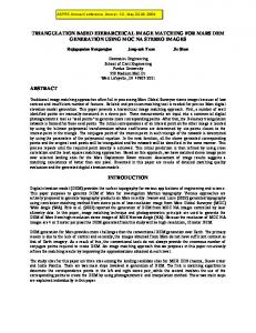
Fig. 7. Simulation of a pair of power-ground planes in comparison with the �m. (b) Electric fields analytical solution. (a) Electric field sampled at z sampled at z ; �m; and �m showing the delay in time.
=0 2
(13) and
7
=2
plier is only seven. In addition, because of the linear dependence , as can be seen from (9), only needs to be between factorized once and reused for other . A. Performance Analysis
Top down
(14) and are then used to scale The two coefficients in a single segment to obtain and in (10) instantly. Hence the cost is minimized. The reduced matrix involves unknowns on two lines. It can be further analytically reduced to involve unknowns on one line as follows:
where
(15) As a result, the reduced single-line matrix is diagonal. Hence, the matrix inversion is avoided. can be perThe recovery of all the vertical unknowns formed as
(16) and in (16) are linearly proportional to Since matrices each other and both are diagonal, again there is no need to invert matrices and perform matrix–vector multiplication. In addition, only needs to be done the inversion of diagonal matrix in (16) are, hence, once and reused for other . Unknowns obtained in linear complexity. The recovery of the horizontal unknowns can be conducted as (17) Since matrices ( ) are tridiagonal, (17) can be performed in linear complexity [21]. The constant multi-
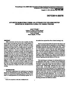
The matrix of is reduced to 1 analytically. The factorization cost of the 1 system is a constant. The time comparameters of interest is with plexity of recovering memory consumption. In addition, the constant multiplier is no greater than seven. It should be noted that even the system matrix is diagonal like what it is in explicit FDTD methods, the 1 factorization complexity cannot be achieved costs since inverting a diagonal matrix of dimension divisions. IV. NUMERICAL RESULTS AND EXPERIMENTAL VALIDATION First, the proposed method is validated with a structure having an analytical solution: a pair of power-ground planes made of perfect conductors. Its width (along ), its height (along ), and its length were set as 10 m. Along the length, the structure was subdivided into ten layers. The dominant transverse electromagnetic mode was launched on the incident . The exact absorbing boundary condition for plane at the dominant mode was placed on both the incident and exiting planes. The incident pulse was the time derivative of a Gaussian , in which pulse was chosen to be 3.0 s and was 4 . The time step s. In total, 50 000 time steps was chosen to be 2.0 10 were simulated. The electric field at m was sampled and compared with the analytical solution, which revealed an excellent agreement, as can be seen from Fig. 7(a). Fig. 7(b) m and m, respectively. depicts the time delay at Clearly, the delay is accurately simulated by the proposed method. With the accuracy validated, we tested the performance of the cross-section of the power-ground proposed method. The plane structure was discretized into 50 segments along and 50 segments along . Along , the structure is discretized into various number of segments from 25 to 200, resulting in 200 000 to more than one million unknowns. The matrix factorization time is plotted with respect to the number of unknowns in Fig. 8(a) in comparison with that cost by a conventional time-domain finite-element method and the LAFE-RR method reported in [14], [15]. Both LAFE-RR and the conventional time-domain finiteelement solver employ the state-of-the-art multifrontal solver to
Authorized licensed use limited to: Purdue University. Downloaded on July 01,2010 at 21:24:54 UTC from IEEE Xplore. Restrictions apply.
GAN AND JIAO: HIERARCHICAL FINITE-ELEMENT REDUCTION-RECOVERY METHOD
281
Fig. 9. Time-domain waveforms of a 100-�m-long test-chip interconnect and V are the voltages structure simulated by the proposed method. (V observed at the near end and far end, respectively.)
Fig. 8. Simulation of a pair of power-ground planes. (a) Decomposition time. (b) CPU cost at each time step. (c) Memory cost in decomposition.
factorize sparse matrices. In this simulation, the layer-growth direction was chosen the same as the length direction, which is . Hence, when increasing the discretization elements along , the single-layer matrix size is increased. As a result, the factorization cost of the LAFE-RR method increases, as can be seen from Fig. 8(a). In contrast, the cost for the matrix factorization of the proposed method is a constant regardless of the number of unknowns. In Fig. 8(b), we plot the CPU cost at each time step versus the number of unknowns for the three methods. Again, the proposed method outperforms the other two methods. The memory consumption of the proposed method for the matrix factorization is also plotted against the number of unknowns in Fig. 8(c) and compared with a conventional time-domain finite-element method and the LAFE-RR method. Once again, the superior performance of the proposed method is observed. Next, a test-chip interconnect structure of length 100 m [22] was simulated. The structure was fabricated using conventional silicon processing technology. It comprised three metal layers and 13 inhomogeneous dielectric stacks. The structure was divided into 338 brick elements in each layer, rendering 715 surface unknowns and 1093 volume unknowns per layer. Due to a nondisclosure agreement, the detailed structure is not given here. Fig. 9 depicts the time-domain waveforms of the sampled voltages at the near and far end of one wire in the interconnect structure, with its near end excited by a current source and the far end left open. Clearly, the results agree with those generated by a conventional time-domain finite-element method. In addition, for this short interconnect structure, it is observed that RC effects are dominant because the sampled voltage behaves as an integration of the current over the time. Since this structure involved different layout structures in different layers, the fast-marching method developed in [16] and [17] was used to increase the time step without sacrificing the stability and efficiency. The fast-marching technique was also used in all the
Fig. 10. Simulation of a test-chip interconnect of length 100 �m. (a) Decomposition time. (b) CPU cost at each time step. (c) Memory cost in decomposition.
following examples that involve different conductor configuration in different layers. The performance of the proposed method was then compared against the time-domain LAFE-RR method and the conventional time-domain finite-element method in Fig. 10. Again, the cost of the proposed method in matrix factorization is a constant. The factorization cost of the LAFE-RR method is also a constant here because the number of unknowns is grown along the longitudinal direction (layer-growth direction) in this example, and hence the single-layer matrix size remains the same. The computer used is an IBM system X3550 with two Intel Woodcrest dual core processors. Next, we considered a three-metal-layer on-chip interconnect structure with orthogonal returns. The geometry is depicted in plane) Fig. 11(a) from both the cross-sectional view (in and the 3-D view. The conductivity of all metals is 5 10 S m.
Authorized licensed use limited to: Purdue University. Downloaded on July 01,2010 at 21:24:54 UTC from IEEE Xplore. Restrictions apply.
282
IEEE TRANSACTIONS ON ADVANCED PACKAGING, VOL. 33, NO. 1, FEBRUARY 2010
Fig. 11. Geometry of a three-metal-layer on-chip interconnect. (a) Cross-sectional view and (b) 3-D view.
Fig. 13. Time-domain waveforms of a 2000-�m-long test-chip interconnect structure.
Fig. 12. Simulation of a 3-D on-chip interconnect.
The conductivity of the silicon substrate is 10 S m. There exist five -orientated wires in M1 and M3 layers, respectively, as shown in Fig. 11(b). The width of these wires is 1 m and the spacing is 1 m. The interconnect length (9 m) along is subdivided into nine layers. Its two ends are both attached to an air layer, which is truncated by a first-order absorbing boundary condition. The top and bottom boundaries along the -direction are perfect electrically conducting boundaries. The left and right boundaries along the -direction are perfect magnetically conducting boundaries. The layer growth direction is chosen as . Each layer is divided into 600 brick elements. The near end of the 1- m-wide wire in M2 was excited by a current source. The source waveform was the time derivative of a Gaussian , in which is pulse 1.0 s and is 4 . The current probe was placed underneath the 1- m-wide wire in the dielectric layer between the M1 layer and M2 layer. The voltage at the near and far end of the 1- m-wide wire was simulated. In Fig. 12, the result obtained by the proposed method is compared with that obtained by a traditional time-domain finite-element method. As shown in Fig. 12, an excellent agreement was observed, which again demonstrates the accuracy of the proposed method. The fourth example is a large-scale test-chip interconnect structure. This interconnect involves 146 parallel returns (parallel to M2 lines) in the M3 layer, two M2 signal lines and two M2 return lines, which are backed by a solid metal plane in M1. The structure is of length 2000 m. The conventional time-domain finite-element method fails to factorize the system
Fig. 14. S-parameters of a 3-D on-chip interconnect simulated by the proposed method.
matrix, whereas the proposed method successfully simulated the S-parameters of the test-chip structure. Fig. 13 depicts the time-domain waveforms, in which “current src” is the current and are source injected at the near end of one M2 wire; the voltages observed at the near ends of the two M2 wires; and are the voltages observed at the far ends. and Clearly, an inductance effect can be observed. Fig. 14 plots the simulated S-parameters in comparison with the measured data. Once again, good agreement is observed. The S-parameters are extracted from the near ends of two M2 wires, which are physically disconnected. As can be seen from Fig. 14, at low is almost zero and hence is close frequencies, crosstalk to one. However, crosstalk increases at high frequencies. We also applied the proposed method to solve a large-scale package-level power delivery problem. The structure involves a bottom ground plane with via holes, a center via layer consisting of both power and ground vias, and a top power plane with via holes. The structure occupies an area of 2500 2500 m . The thickness of each layer is 0.03, 0.025, and 0.03 mm, respectively. A bottom power via is excited by a current source as
Authorized licensed use limited to: Purdue University. Downloaded on July 01,2010 at 21:24:54 UTC from IEEE Xplore. Restrictions apply.
GAN AND JIAO: HIERARCHICAL FINITE-ELEMENT REDUCTION-RECOVERY METHOD
283
ACKNOWLEDGMENT The authors would like to thank Dr. M. J. Kobrinsky and Dr. S. Chakravarty at Intel Corporation for providing measured data and Dr. W. Shi at Intel Corporation for providing package power delivery structures.
Fig. 15. Time-domain waveforms of a package-level power delivery structure simulated by the proposed method.
Fig. 16. Simulation of a package-level power delivery structure. Voltage map s, (b) t s, and (c) t s. : sampled at (a) t
= 2210
= 3210
= 3 7210
shown by in Fig. 15. The voltages sampled at the source location and the other two via locations also are shown in Fig. 15. In Fig. 16, the voltage map of the bottom ground plane is given at three time instants. A dynamic voltage variation over the ground plane can be clearly observed. V. CONCLUSION In this paper, a hierarchical finite-element reduction-recovery method is proposed to simulate large-scale high-speed ICs in is hitime domain. In this method, the system matrix of erarchically and analytically reduced to a system of 1 , thus enabling a significant reduction in computational complexity. The matrix factorization time is a constant irrespective of the problem size. The unknown recovery time scales linearly with the number of unknowns. It is applicable to any Manhattan-type integrated circuit embedded in layered media. Numerical and experimental results demonstrate its superior performance.
REFERENCES [1] C. C. Chen, T. Lee, N. Murugesan, and S. C. Hagness, “Generalized FDTD-ADI: An unconditionally stable full-wave Maxwell’s equations solver for VLSI interconnect modeling,” in Proc. IEEE/ACM 2007 Int. Conf. Computer-Aided Design (ICCAD), Nov. 2000, pp. 156–163. [2] A. Rong and A. C. Cangellaris, “Generalized PEEC models for threedimensional interconnect structures and integrated passives of arbitrary shapes,” in Proc. IEEE 10th Topical Meeting Electr. Perform. Electron. Packag., Oct. 2001, pp. 225–228. [3] A. E. Ruehli, G. Antonini, J. Esch, J. Ekman, A. Mayo, and A. Orlandi, “Nonorthogonal PEEC formulation for time- and frequency-domain EM and circuit modeling,” IEEE Trans. Electromagn. Compat., vol. 45, no. 2, pp. 167–176, May 2003. [4] D. Gope, A. E. Ruehli, C. Yang, and V. Jandhyala, “(S)PEEC: Timeand frequency-domain surface formulation for modeling conductors and dielectrics in combined circuit electromagnetic simulations,” IEEE Trans. Microwave Theory Tech., vol. 54, no. 6, pp. 2453–2464, Jun. 2006. [5] D. Jiao, C. Dai, S.-W. Lee, T. R. Arabi, and G. Taylor, “Computational electromagnetics for high-frequency IC design,” in Proc. IEEE Int. Symp. Antennas Propag., 2004, pp. 3317–3320. [6] P. J. Restle, A. E. Ruehli, S. G. Walker, and G. Papadopoulos, “Fullwave PEEC time-domain method for the modeling of on-chip interconnects,” IEEE Trans. Computer-Aided Design, vol. 20, no. 7, pp. 877–887, Jul. 2001. [7] Z. H. Zhu, B. Song, and J. K. White, “Algorithm in FastImp: A fast and wideband impedance extraction program for complicated 3-D geometries,” in Proc. 40th ACM/IEEE Design Automation Conf., Jun. 2003, pp. 712–717. [8] W. C. Chew, “Toward a more robust and accurate fast integral solver for microchip applications,” in Proc. IEEE 12th Topical Meeting Electr. Perform. Electron. Packag. (EPEP), Oct. 2003, p. 333. [9] S. Kapur and D. E. Long, “Large-scale full-wave simulation,” in Proc. 41th ACM/IEEE Design Autom. Conf., 2004, pp. 806–809. [10] A. E. Yilmaz, J. M. Jin, and E. Michielssen, “A parallel FFT-accelerated transient field-circuit simulator,” IEEE Trans. Microwave Theory Tech., vol. 53, no. 9, pp. 2851–2865, Sep. 2005. [11] F. Ling, V. I. Okhamtovski, W. Harris, S. McCracken, and A. Dengi, “Large-scale broad-band parasitic extraction for fast layout verification of 3D RF and mixed-signal on-chip structures,” IEEE Trans. Microwave. Theory Tech., vol. 53, no. 1, pp. 264–273, Jan. 2005. [12] Y. Wang, V. Jandhyala, and C. J. Shi, “Coupled electromagnetic-circuit simulation of arbitrarily-shaped conducting structures,” in Proc. IEEE 12th Topical Meeting Electr. Perform. Electron. Packag. (EPEP), 2001, pp. 233–236. [13] Z. Cendes and A. Yen, “Mixed electromagnetic and electrical circuit simulation for RFIC characterization,” in Proc. IEEE Antennas Propag. Society Int. Symp., 2004, vol. 3, pp. 3289–3292. [14] H. Gan and D. Jiao, “A fast and high-capacity electromagnetic solution for high-speed IC design,” in Proc. IEEE/ACM 2007 Int. Conf. Computer-Aided Design (ICCAD), 2007, pp. 1–6. [15] H. Gan and D. Jiao, “A time-domain layered finite element reduction recovery (LAFE-RR) method for high-frequency VLSI design,” IEEE Trans. Antennas Propag., vol. 55, no. 12, pp. 3620–3629, Dec. 2007. [16] H. Gan and D. Jiao, “A fast-marching time-domain layered finite-element reduction-recovery method for high-frequency VLSI design,” in Proc. IEEE Int. Microwave Symp., Jun. 2008, pp. 169–172. [17] H. Gan and D. Jiao, “A fast-marching time-domain layered finite-element reduction-recovery method for high-frequency VLSI design,” IEEE Trans. Antennas Propag., vol. 57, no. 2, pp. 577–581, Feb. 2009. [18] D. Chen and D. Jiao, “Time-domain orthogonal finite-element reduction-recovery (OrFE-RR) method for fast and accurate broadband simulation of die-package interaction,” in Proc. IEEE 17th Conf. Electr. Perform. Electron. Packag. (EPEP), Oct. 2008, pp. 287–290. [19] D. Jiao and J. M. Jin, “Finite element analysis in time domain,” in The Finite Element Method in Electromagnetics. New York: Wiley, 2002, pp. 529–584. [20] J. M. Jin, The Finite Element Method in Electromagnetics, 2nd ed. New York: Wiley, 2002.
Authorized licensed use limited to: Purdue University. Downloaded on July 01,2010 at 21:24:54 UTC from IEEE Xplore. Restrictions apply.
284
IEEE TRANSACTIONS ON ADVANCED PACKAGING, VOL. 33, NO. 1, FEBRUARY 2010
[21] G. Meurant, “A review on the inverse of symmetric tridiagonal and block tridiagonal matrices,” SIAM J. Matrix Anal. Applicat., vol. 13, no. 3, pp. 707–728, Jul. 1992. [22] M. J. Kobrinsky, S. Chakravarty, D. Jiao, M. C. Harmes, S. List, and M. Mazumder, “Experimental validation of crosstalk simulations for on-chip interconnects using S-parameters,” IEEE Trans. Adv. Packag., vol. 28, no. 1, pp. 57–62, Feb. 2005.
Houle Gan (S’08) received the B.S. and M.S. degrees in information science and electronic engineering from Zhejiang University, Hangzhou, China, in 2003 and 2006, respectively. He is now pursuing the Ph.D. degree in the School of Electrical and Computer Engineering, Purdue University, West Lafayette, IN. In 2006, he was a System Engineer with Realsil Microelectronics Inc., Suzhou, China. In September 2006, he joined the On-Chip Electromagnetics Group, Purdue University, as a Research Assistant. His current research interest is computational electromagnetics for large-scale high-frequency integrated circuit design. Mr. Gan received an IEEE Antennas and Propagation Society Ph.D. Research Award for 2008–2009.
Dan Jiao (S’00–M’02–SM’06) received the Ph.D. degree in electrical engineering from the University of Illinois, Urbana-Champaign, in October 2001. She was with the Technology CAD Division, Intel Corporation, as a Senior CAD Engineer, Staff Engineer, and then Senior Staff Engineer. In September 2005, she joined the School of Electrical and Computer Engineering, Purdue University, West Lafayette, IN, as an Assistant Professor. In April 2009, she was promoted to Associate Professor with tenure. She has authored two book chapters and more than 90 papers in refereed journals and international conferences. Her current research interests include high-frequency digital, analog, mixed-signal, and RF IC design and analysis, high-performance VLSI CAD, modeling of micro- and nanoscale circuits, computational electromagnetics, applied electromagnetics, fast and high-capacity numerical methods, fast time-domain analysis, scattering and antenna analysis, RF, microwave, and millimeter-wave circuits, wireless communication, and bioelectromagnetics. Dr. Jiao received a National Science Foundation CAREER Award in 2008. In 2006, she received the Jack and Cathie Kozik Faculty Start-up Award, which recognizes an outstanding new faculty member in Purdue’s Electrical and Computer Engineering Department. She also received an ONR award through the Young Investigator Program. In 2004, she received the Best Paper Award from Intel’s annual corporate-wide Design and Test Technology Conference for her work on generic broadband model of high-speed circuits. In 2003, she received the Intel Logic Technology Development (LTD) Divisional Achievement Award in recognition of her work on the industry-leading BroadSpice modeling/simulation capability for designing high-speed microprocessors, packages, and circuit boards. She received the Intel Technology CAD Divisional Achievement Award for the development of innovative full-wave solvers for high-frequency IC design. In 2002, she received the Intel Hero Award for timely and accurate twoand three- dimensional full-wave simulations. She also won the Intel LTD Team Quality Award for her outstanding contribution to the development of the measurement capability and simulation tools for high-frequency on-chip crosstalk. She received the 2000 Raj Mittra Outstanding Research Award from the University of Illinois at Urbana-Champaign. She has been a reviewer for many IEEE journals and conferences.
Authorized licensed use limited to: Purdue University. Downloaded on July 01,2010 at 21:24:54 UTC from IEEE Xplore. Restrictions apply.