Int. J. Embedded Systems, Vol. X, No. Y, 200x
1
A system for application development using aerial robots Mohammad Fraiwan*, Ahmad Alsaleem, Hashem Abandeh and Omar Aljarrah Department of Computer Engineering, Jordan University of Science and Technology, P.O. Box 3030, Irbid 22110 Jordan Email:
[email protected] Email:
[email protected] Email:
[email protected] Email:
[email protected] *Corresponding author Abstract: Autonomous airborne systems have generated a lot of interest in civilian, as well as, military applications. The application development process for such systems is inherently expensive and is prone to costly errors. The majority of the developed applications involve routing and navigation toward targets coupled with obstacle avoidance. In this paper, we present the approach and algorithms that were employed to tackle the routing and avoidance problems. The proposed solutions were applied to land-based robots as well as a quad-rotor aerial system. The quad-rotor flight path navigation and routing was programmed based on GPS and on-board measurement data. Obstacle avoidance was implemented based on an algorithm that relies on the idea of virtual potential field. Kalman filters were implemented to improve the accuracy of the measured data. While 3D visualisation was used to visually identify obstacles. In the case of in-building reconnaissance, where GPS signals are very weak and largely useless, data from laser sensors and proximity feeds was aggregated and processed to identify obstacles and the topology of the surrounding environment. The organisation and interaction of these various modules is described in details. Keywords: quad-rotor; obstacle avoidance; Kalman filter; maps; potential field. Reference to this paper should be made as follows: Fraiwan, M., Alsaleem, A., Abandeh, H. and Aljarrah, O. (xxxx) ‘A system for application development using aerial robots’, Int. J. Embedded Systems, Vol. X, No. Y, pp.xxx–xxx. Biographical notes: Mohammad Fraiwan received his BS (with honours) in Computer Engineering from the Jordan University of Science and Technology (JUST), Jordan and PhD from the Iowa State University (ISU), USA in 2003 and 2009, respectively. He is currently an Associate Professor in the Computer Engineering Department at JUST. His main research interests include network monitoring, biomedical applications, datamining, and computer systems and applications. He spent an unpaid leave at the Institute of Applied Technology (IAT), Abu Dhabi, UAE from February 2014 to February 2016. He worked at the Akamai Technologies, Boston, USA in the summer of 2008, and as a Visiting Scientist at the ISU during the summers of 2009 and 2010. Ahmad Alsaleem received his Bachelor’s in Computer Engineering from the Jordan University of Science and Technology in 2013 and Master’s from the Utah State University, USA in 2016. He is currently enrolled for PhD in Computing at the University of Utah Hospitals and Clinics. Hashem Abandeh received his Bachelor’s in Computer Engineering from the Jordan University of Science and Technology in 2013. During his studies, he contributed to two funded projects and a conference paper. The work in this paper was conducted as part of his graduation project. He is currently a Software Engineer at ETQ, Amman, Jordan. Omar Aljarrah is the President of Jordan University of Science and Technology (JUST), Irbid, Jordan (July 2016–current). He is a Professor of Computer Engineering at the JUST. He received his BSc in Electrical Engineering from the JUST in 1991, MSc and PhD in Electrical and Computer Engineering from the Ohio State University in 1994 and 1996, respectively. His research interests include artificial intelligence, computer networks, and e-learning. He has published 66 technical papers in well-reputed international journals and conferences. During his career, he has supervised more than 100 graduate and undergraduate students.
Copyright © 20XX Inderscience Enterprises Ltd.
2
M. Fraiwan et al. This paper is a revised and expanded version of a paper entitled ‘Obstacle avoidance and navigation in robotic systems: a land and aerial robots study’ presented at 5th International Conference on Information and Communication Systems (ICICS 2014), Irbid, Jordan, 1–3 April 2014.
1
Introduction
Robots have long attracted human interest. Intelligent robot development is a long-running wide-ranging research area. In the past few years, unmanned aerial vehicles (UAVs), or drones, have increased in prominence due to the number of possible civilian and military applications. Just recently, Amazon has announced that it will be using UAVs to deliver packages to customers in the next few years pending proper usage regulations by the US Government (Amazon Prime Air, 2016). Moreover, the USA have recently announced a set of six test sites all around the country with the goal of developing proper safety and operational regulations, advancing the UAV technology, and testing commercial usage (US Drone Sites Announcement, 2013). Aviation technology has become ubiquitous, reliable, and cheap enough to allow for the development of sophisticated applications with relative ease. The majority of the complex flight control and avionic functionalities are readily available so as the road is paved for innovation. Quad-rotor also known as a quad-rotor helicopter did made the research area wide open because of the features that came with these type of UAVs. Military and security applications such as close range recognisance, agricultural applications, and commercial delivery are some of the major applications attracting great attention. The unpredictability of the deployment environments makes obstacle avoidance one of the major problems in using unmanned vehicles. Achieving deployment goals relies on autonomous navigation and avoiding the obstacles in the environment. Autonomy is needed to deal with sudden appearance of different types of obstacles and to make on-site decisions. Moreover, it is required in cases were the decisions need to be made in prompt real-time situations to avoid errors caused by the slow human decision-making process. In this paper, we tackle the navigation, routing, and obstacle avoidance problems associated with UAV deployment. To conserve resources, we initially applied all algorithm to a land-based robot, the Pioneer 3DX (2014), as a test vehicle. Only when the algorithms are fully verified and the implementation checked, we moved to the quad-rotor testing. For the UAV, we employed the Asctec Pelican quad-rotor (Ascending Technologies, 2016). The overall system organisation is described in details pointing out the data filtration using Kalman filter, obstacle avoidance algorithm, 3D environment creation and mapping, and the interaction among the various system components. Routing functionalities were programmed and relayed to the quad-rotor and the land robot using wireless connections. A map of the deployment area is fed to the
system from Google Maps (Google Maps, 2016). The flight path is then fed to the UAV as a set of points, which will be traversed in a certain order. The crux of the work involves obstacle avoidance, which will be detailed in the remainder of the paper. To achieve obstacle avoidance from on-board sensor proximity values, we applied 2D planner algorithms in 3D. The 2D planner of choice is based on the virtual potential field (VPF) approach. Much like magnetic fields, VPF treats targets and obstacles as charged particles that attract and repulse the UAV, respectively. By establishing potential fields around obstacles and targets, we can simulate this effect and navigate the robot around obstacles and toward the targets. An attractive field surrounds the target. The potential field is defined across the entire free space. In each time step, we measure the potential field around the robot position. Then, calculate the induced force by this field and the robot will move according to this force. We calculate the relative distance between the robot and the target, the required force is applied to drive the robot to the target and away from the obstacle. The remainder of this paper is organised as follows. Background into the importance of the subject along with related work is presented in Section 2. Section 3 discusses obstacle avoidance in land-based robots. Section 4 shows the quad rotor-based system architecture, and explains the interaction of the various components. Section 5 details the various components and algorithms of the quad rotor data analysis and filtration, routing, and obstacle avoidance. We conclude in Section 6.
2
Background and related work
Multiple flight solutions are commercially available with reasonably cheap cost. We give details of two aspects related to our contribution: 1
avionic technology and capabilities
2
applications.
2.1 Avionic technology and capabilities Current small-scale flying solutions offer a very high thrust to weight ratio, a varying number of rotors (4, 6, or 8), and great onboard capabilities (GPS, 3D campus, ARM7, Intel Atom Processor, laser depth sensors, and night vision). Moreover, some of these solutions are made from carbon fibre material, which is ultra light weight material. Capabilities (Ascending Technologies, 2016):
A system for application development using aerial robots •
•
•
Number of rotors: The large numbers of available rotors (up to 8) provides high lift capabilities and fault tolerance. GPS: For location awareness and navigation, this is possible by the on-board 3D campus. Li et al. (2016) have examined the use of low cost sensor in case of GPS outages.
3
3
As a starting point, all algorithms were implemented and tested on the Pioneer 3DX (2014) robot. This robot has on-board cameras as well as a sonar-based proximity sensor. It also features remote control and guidance capabilities. Algorithm 1
Laser depth sensors. This provides highly valuable information for obstacle avoidance programs. Some studies have employed the Kinect depth sensor (Chen et al., 2016).
•
Night vision, thermal, and daytime cameras: Provide excellent monitoring and surveillance tools.
•
The ARM7 and Atom processors: provide us with great processing power to create and program sophisticated applications.
•
•
Reconnaissance and monitoring: Future application scenarios include robotic security guards that can rapidly react to a triggered alarm by autonomously providing surveillance of a specific site or area. Other tasks centre around autonomous border patrol and perimeter search. See Figure 2. Firefighting (Full Spectral Imaging and a New System for Remote Sensing and Environmental Monitoring, 2011).
•
Agricultural (Drones in Agriculture, 2014).
•
Environmental (Dobers, 2011).
•
Rescue operations (Murphy, 2004).
•
Parcel delivery (Amazon Prime Air, 2016).
The obstacle avoidance algorithm
Data: dt: Distance to target // The Cartesian distance r: virtual field radius around target Qt: atan2(x, y) // The arc tangent of the difference in coordinates between robot and target do: Distance to obstacle ro: virtual field radius around obstacle Qo: atan2(x, y) // The arc tangent of the difference in coordinates between robot and obstacle
2.2 Applications There are many situations that present a hazard for humans to venture into (e.g., building collapse, radiation, fire, etc.). For example, when the crane at the Jordan Gate project collapsed (Jordan Times, 2009), it was left dangerously hanging pending rescue crew intervention, dismantling, and maintenance. Traditionally, remote-controlled land-based robots equipped with cameras were used to explore hazardous areas and objects (Murphy, 2004). Such systems have achieved a great deal of success in dealing with search and rescue missions. However, there are conditions were such systems are hindered by debris, natural obstacles, mobility, heat, and many other natural factors impeding the movement of land-based objects. Such missions require high agility, manoeuvrability, and obstacle avoidance capabilities. Land-based robots lack in this regards. Moreover, the robots need to have a degree of autonomous capabilities in order to react to external circumstances. Once provided with cheap, versatile aerial solutions. The door opens for a great number of applications are of use to the local community, a few of these include:
Obstacle avoidance in land robots
f actor speed_factor 1
Assume initial robot position (x = 0, y = 0)
2
Calculate distance to obstacle
3
Calculate the angle between obstacle and robot
4
Calculate the distance between the robot and target along with the angle /* Target check
5 6
*/
if dt > r then x_to_target = 0, y_to_target = 0
7
end
8
if (dt < r AND dt + speed_factor < dt) then // Start decreasing speed of robot
9 10 11
x_to_target = factor × (dt – r) × cos(Qt) y_to_target = factor × (dt – r) × sin(Qt) else // Move full speed to target
12
x_to_target = factor × cos(Qt)
13
y_to_target = factor × sin(Qt)
14
end /* Obstacle check
15
if (do < ro) then x_to_obstacle = –factor × cos(Qo)
16
y_to_obstacle = –factor × sin(Qo); /* else if too close to obstacle the slow down and reverse direction
17 18 19 20
else if (do > r AND do < (r + speed_factor)) then x_to_obstacle = –b × (factor + r – do) × cos(Qo) y_to_obstacle = –b × (factor + r – do) × sin(Qo) else // collision with obstacle
21
x_to_obstacle = 0
22
y_to_obstacle = 0
23
end
*/
*/
4
M. Fraiwan et al. 24
x = x_to_obstacle + x_to_target
25
y = y_to_obstacle + y_to_target
26
Go to step 2
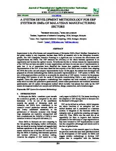
We employed Algorithm 1 for obstacle avoidance, which is based on the VPF idea as mentioned earlier. In this algorithm, if the object is moving in the field of the target then it will start decreasing its speed (line 8), and if it is outside the target’s field then it will move in a speed proportional to the power of the target’s field. Once it reaches the target then it will stop. As for the obstacle, if the moving object is inside the obstacle’s potential field then it will slow down and change its direction and orientation. Hence, the negative sign in the equation at line 16. Moreover, if the moving object is not within the range of the obstacle’s field then no change is applied. Figures 1(a) and 1(b) show the MATLAB simulation using the one stationary and two moving obstacles, respectively. It clearly shows the effectiveness of the approach in avoiding obstacles. The algorithm was also implemented to work with the P3DX robot. Figure 2(a) shows video snapshots of the robot moving toward the target while avoiding obstacles in the lab. Figure 2(b) shows the same experiment from the live feed from the robot’s camera along with a map of the location.
4
System architecture
•
On-board processor: An ARM processor that makes the required calculations and decisions to stabilise the flight system. Most of the components at this level are from the quad-rotor manufacturer Ascending Technologies (2016). The Kalman filter improves the accuracy of the data received through the IMU’s.
Table 1 shows the various types of data exchanged among the three-system components and the technologies employed. Table 1
Communication links and data exchanged among the various system components
End points
Tech.
Data exchanged
Base station ↔ Atom board
Wi-Fi
Receive: Laser scans data, IMU filtered measurements, and enhanced GPS data. Send: GPS goals, indoor location
Remote controller ↔ On-board controller
ZigBee
RC commands for directly controlling the quad-rotor
Serial
Receive: Raw IMU and GPS data. Send: control commands
Atom board ↔ On-board controller Figure 1
MATLAB simulation of robot movement with stationary and moving obstacles (a) one stationary obstacle (b) two moving obstacles
Due to the availability of three processing modules and the need to build a comprehensive system that embodies a lot of functions, we opted for a multi-level system design, see Figure 4. Data communication speed and the available processing power in each level of the purposed system were the main factors in accommodating the required functionalities (e.g., data filtration). The three-system components are as follows: •
•
Base station: The base station represents a workstation (desktop or laptop in our case) with wireless communication to the quad-rotor. Through the base station, a graphical interface is provided along with a set of tools for control, addition of navigation points using GIS maps and GPS, simultaneous localisation and mapping (SLAM)-based 2D and 3D graphical visualisation of the deployment area of the quad-rotor, and the GPS position of the quad-rotor alongside the IMU readings. Atom board: A portable processing system powered by an Intel 1.8 GHZ CPU and 1 GB of RAM, all attached to the Quad-rotor. The Atom board is responsible for collecting data from the attached sensors and laser scanner and relaying this data through the wireless connection to the base station in a proper format. In the same time, the Atom board is used to calculate the next hop, along the path to the destination, using the 2D planner algorithm. These coordinates are relayed through the serial connection to the basic on-board processor.
(a)
(b)
A system for application development using aerial robots Figure 2
A live view of the obstacles and the robot based on data feed from the robot, (a) video recording (b) video feed and robot position overlaid on map (see online version for colours)
(a)
(b)
5
6
M. Fraiwan et al.
Figure 3
The proposed system architecture (see online version for colours)
4.1 User interface For our navigation system, we are targeting a large range of system users, ranging from novices to experts. To this end, we have developed the following components: •
Environment creator: This component displays a graphical representation of the area the quad-rotor is flying in. Showing a floor plan for the area with the help of the laser scans. This has been done through the SLAM and Oct Tree algorithms provided though the robotic operating system (ROS) stack (Willog Garage, 2012).
•
Data visualisation: Represents IMU measurements and laser scans through RVIZ (data visualiser software).
5
Obstacle avoidance and navigation in quad rotor aerial robot
Once the majority of the algorithms were implemented and tested on the P3DX, we moved into the quad-rotor deployment. However, the transition is not straight forward. We have encountered several issues mainly regarding obstacle representation. In the next subsections, we go through the details of our approach to quad-rotor navigation and obstacle avoidance.
5.1 Quad-rotor navigation Figure 4 shows the Xcontrol interface (Ascending Technologies, 2016), which displays various flight parameters like location altitude, GPS data, rotor altitude, battery levels, speed, yaw, etc. This data is collected by the rotor’s inertial measurement unit (IMU) and presents the
operator with a live feed of information from the on-board sensors. This same set of data can be used to program autonomous navigation and obstacle avoidance. Figure 4 shows the interface used to program the flight path. This interface shows a live feed of the various flight parameters (e.g., location and speed) as provided by the quad rotor. Moreover, it provides capabilities to control the direction, speed, flight mode and altitude. Based on Google Earth maps (Google Maps, 2016) (or any other mapping service), the flight path is entered as a set of points to be traversed by the rotor in a predetermined order. The figure shows a path that instructs the rotor to follow the perimeter of a rectangular area.
5.2 Data filtration In the quad-rotor, we have multiple sensors with the purpose of identifying the exact position of the rotor. This data suffers from time lag because of the fast movement of the rotor, the slow speed of the UART serial communication link between the IMU and sensors, and the delay of ZigBee-based communication between the rotor and the base station. Also, the data may suffer from inherent noise and errors. To improve the accuracy of the data, we employed a Kalman filter (CCNY Robotics Lab, 2012) to the data. Figure 6 shows the actual intended movement path along with the measured data, and the improved (filtered data). Such filtration greatly improves the accuracy of efficacy of obstacle avoidance.
5.3 Obstacle and environment representation The Pioneer 3DX had sonar proximity sensor, where as our quad-rotor as the Ascending Technologies (2016) Pelican. We equipped the Pelican with a Hokuyo laser range finder
A system for application development using aerial robots (UTM-30LX Scanning Range Finder, 2014) with a 30 m detection range, which is suitable for fast moving objects. The literature is rich with real-time detection systems of stationary and moving objects (Tang et al., 2016). The complete flight path is divided into local paths. Thus we have a global planer for the whole path, and the local planner for the local paths. The local planner follows the VPF algorithm to avoid obstacles and move the rotor toward the next point along the path set forth by the global planner. Based on raw laser data only, the task now is to determine the rotor location, shape of the environment, and move in the proper direction. Algorithm 2
1
S0 = (0, 0, 0, degree)
2
For next scan Si+1 calculate next coordinates relative to previous point.
5
Connect the set of points with the minimum error factor
To achieve environment and obstacle awareness, we employed a canonical scan matcher (CSM) algorithm, see Algorithm 2. The ROS provides raw intermittent data from laser scans. The scan matcher aggregates this data to clearly model the surrounding environment. The algorithm works Figure 4
OL most recent location output:
A map drawn based on the sample data
for i ← 1 to n – 1 do // ⊕: combining pose estimations Xi = xi ⊕ OL // Choose the maximum likelihood observation
*/
Repeat step 2 till minimum error is achieved
St–1 Laser scans Lt most recent laser scan
2
/* Calculate the error of the previous step as the minimum Distance 4
input:
SLAM algorithm
// Initial guess about position
*/
Function Error(i) = Function MinDistance(Pi(t))
Algorithm 3
*/
/* Find the minimum distance of a point relative to the previous coordinates
3
by considering each laser scan as a set of 2D points (Censi, 2008; Nuchter, 2009). Each pair of points from a group of laser scans is connected to its nearest neighbour. Thus, it provides a continuous graphical representation. Figures 7 and 8 show the visualisation of this data.
1
CSM algorithm
/* First laser scan determines point of origin
7
Xˆ i = max P (OL , X i )
3
4
end
5
Choose a set of sampling points around pose Xˆ i
6
Draw the map based on the samples
The purpose of the SLAM algorithm, see Algorithm 3, is to determine the exact position and pose of the rotor while moving. It also reflects this information on the deployment map. It does not accept raw data, but need the CSM to aggregate this data. The use of SLAM is imperative for indoor deployment, where GPS signals typically fade away. It also improves the accuracy of outdoor navigation.
A screenshot of the Xcontrol quad rotor data viewer showing the various parameters (see online version for colours)
8
M. Fraiwan et al.
Figure 5
The flight path programmed and overlayed on a Google Map showing JUST soccer field (see online version for colours)
Figure 6
Data filtration showing that the Kalman filter is effective in correcting the flight data
6
Conclusions
UAVs have garnered a lot of research interest in the past few years. UAVs have found their way into a lot of civilian and military applications in what is now considered a multibillion dollars industry, and growing. Small UAVs offer cheap solutions along with great flexibility and ease of operation. In addition, these UAVs are increasingly equipped with more sensing, communication, and payload capabilities. Central to the application development using aerial robots are the problems of navigation, routing, and obstacle avoidance. If these functions are readily available then the process becomes straight forward for the commercial as well as the research community.
In this paper, we have detailed a system for the application development using aerial robots. The process starts on the ground with a land-based robot that is less prone to damage and can tolerate development errors. After that, a full-fledge aerial system was described in details. The system can handle intense data measurements and the accompanied errors via the use of Kalman filters. This data was also used to establish environment awareness and obstacle avoidance by building 3D models. Obstacle avoidance was also demonstrated along with map-based navigation. The future is bright for unmanned aerial systems; with the technology continuously improving, the costs are coming down, and many applications are finding this type of aerial capabilities useful. Tailoring UAVs to specific
A system for application development using aerial robots missions and applications would be an interesting research direction. Figure 7
A 3D view of our research lab based on laser sensor data (see online version for colours)
Figure 8
A 3D view of our research lab in real-time using Rviz data visualiser (see online version for colours)
Acknowledgements We would like to thank Jordan University of Science and Technology (JUST) deanship of research for supporting this work through research grant 20110266. This research was funded in part by King Abdullah Design and Development Bureau (KADDB) in association with King Abdullah II Fund for Development (KAFD) research grant 12/2012.
9
References Amazon Prime Air (2016) Amazon Prime Air Delivery Service [online] http://www.amazon.com/b?node=8037720011 (accessed 7 April 2016). Ascending Technologies (2016) The Asctec Pelican from Ascending Technologies [online] http://www.asctec.de/uavapplications/research/products/asctec-pelican/ (accessed 8 April 2016). CCNY Robotics Lab (2012) [online] http://134.74.16.73/wiki (accessed 4 January 2013). Censi, A. (2008) ‘An ICP variant using a point-to-line metric’, Proceedings of the IEEE International Conference on Robotics and Automation (ICRA). Chen, C., Chiang, S. and Wu, C. (2016) ‘Path planning and obstacle avoidance for omni-directional mobile robot based on Kinect depth sensor’, Int. J. of Embedded Systems, Vol. 8, No. 4, pp.343–351. Dobers, E.S. (2011) ‘Air photo interpretation for spatial analysis of land use systems’ [online] http://www.proland.iung.pulawy.pl/materials/ (accessed 25 May 2011). Drones in Agriculture (2014) [online] http://www.bbc.com/future/story/20140109-dronesfrombattlefield-to-farm (accessed 10 April 2016). Full Spectral Imaging and a New System for Remote Sensing and Environmental Monitoring (2011) [online] http://fullspectralimaging.net/hssri.aspx (accessed 5 May 2011) Google Maps (2016) [online] https://maps.google.com/ (accessed 8 April 2016). Jordan Times (2009) ‘Collapsed Jordan Gate crane to be dismantled this weekend’, 12–13 June, Jordan Press Foundation, Amman, Jordan. Li, Y., Li, X., Havyarimana, V., Wang, D. and Xiao, Z. (2016) ‘Low-cost sensors aided vehicular position prediction with partial least squares regression during GPS outage’, Int. J. of Embedded Systems, Vol. 8, Nos. 2/3, pp.125–214. Murphy, R. (2004) ‘Human-robot interaction in rescue robotics’, in IEEE Transactions on Systems, Man, and Cybernetics, Part C: Applications and Reviews, May, Vol. 34, No. 2, pp.138–153. Nuchter, A. (2009) ‘3D robotic mapping: the simultaneous localization and mapping problem with six degrees of freedom’, Springer Tracts in Advanced Robotics, ISBN 978-3-540-89883-2, DOI 10.1007/978-3-540-89884-9. Pioneer 3DX (2014) Mobile Robots Pioneer P3DX [online] http://msdn.microsoft.com/enus/library/bb483031.aspx (accessed 10 April 2016). Tang, Z., Lin, Z., Li, B. and Chen, L. (2016) ‘The embedded real-time detection system of moving object based on improved Gaussian mixture model’, Int. J. of Embedded Systems, Vol. 8, Nos. 2/3, pp.119–124. US Drone Sites Announcement (2013) [online] http://www.bbc.co.uk/news/world-us-canada-25552825 (accessed 7 April 2016). UTM-30LX Scanning Range Finder (2014) [online] http://www.hokuyoaut.jp/02sensor/07scanner/utm_30lx.html (accessed 10 April 2016). Willog Garage (2012) Robot Open Source (ROS) [online] https://www.willowgarage.com/pages/software/rosplatform (accessed 10 April 2016).