general purpose processor for a wireless body area sensor network node. The heart of the sensor node is the IPMS430 processor core. This processor core is a ...
A System-On-Chip for Wireless Body Area Sensor Network Node Z. Stamenkovi�, G. Pani�, and G. Schoof IHP GmbH Im Technologiepark 25 15236 Frankfurt (Oder), GERMANY Abstract - The paper describes the design, implementation, and verification of a system-on-chip aimed to play the role of a general purpose processor for a wireless body area sensor network node. The heart of the sensor node is the IPMS430 processor core. This processor core is a clone of the Texas Instruments MSP430 microcontroller’s central processing unit. The implemented and verified system includes the processor core, program and data memories, timer, input/output port, and interrupt chain. The paper ends presenting electrical and physical features of the implemented system-on-chip.
I.
INTRODUCTION
Wireless Body Area Sensor Networks (WBASN) are networks of a limited number of nodes, typically less than ten, deployed in an ad hoc fashion to cooperate for sensing one or more physical phenomena [1]-[6]. They offer a high capability of processing and communicating data in medical and surveillance applications. In the TANDEM project [6], we propose a flexible sensor network node architecture, which allows an easy adaptation to the application type and scenario. In principle, the sensor node should consist of a processor, wireless communication unit, one or two sensor interfaces, flash memory, random access memory and possibly PROM. Eventually, some hardware accelerators are needed for functions that cannot be efficiently executed in software by the processor. Such functions are normally time critical or resource intensive. We assume that parts of the medium access and network/transport protocol, and the whole digital base-band are implemented in hardware. All these components should be interconnected by a bus system. The actual node size is defined by the processor type and memory size, and depends on the application type and scenario. The proposed architecture allows also an easy reconfiguration or adaptation of the sensor node according to the transmission cycle or channel access mechanism. The processor is assumed to have a word width of 16 bit and work at an operating frequency of few megahertz to be energy-efficient. An example of such a processor is the TI MSP430. The processor has to perform tasks like protocol processing, signal analysis and management of the sensor node. A small real-time operating system like TinyOS [7] or Reflex [8] should run on it. The sensor node should include different types of memory. Program code, an operating system and basic parameters are stored in PROM. Further, a flash memory should be used to store registers, running program code and present settings if the sensor node goes into some kind of deep sleep mode. Some volatile random access memory is necessary for operating purposes in the working phase of the sensor node. 978-1-4244-2277-7/08/$25.00 ©2008 IEEE
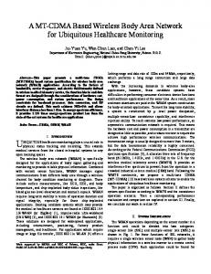
The I/O component connects the wireless sensor node with one or more sensors. In case that the node has bridge/gateway functionality, an interface to the backbone network is necessary. The node should contain an analogue front-end for corresponding wireless standard. The final goal of the project is to design and implement a node for wireless body area sensor network that integrates a general purpose processor, memory, hardware accelerators, standard input/output component, digital base-band and analog front-end on a single chip. In the starting phase, we implemented a highperformance low-power system-on-chip based on IPMS430 processor core [9], which plays the role of a general purpose processor for a wireless body area sensor network node. The paper is organized as follows. The system architecture as well as configuration details are presented in Section II. The system implementation flow, verification methodology, and chip features are summarized in Section III. The conclusion is given in Section IV. II. SYSTEM ARCHITECTURE The system-on-chip includes, beside a processor core, a clock divider, program and data memories, no flash memory, two additional peripherals (timer and input/output port), interrupt chain, and glue logic. The system is described by synthesizable VHDL. The architecture of the configured system is presented in Figure 1.
Figure 1. System architecture
A. IPMS430 Processor Core The IPMS430 processor core is an IP core designed by IPMS, Fraunhofer in form of a VHDL model [10]. It is a clone of the Texas Instruments MSP430 microcontroller’s central processing unit [11]. It is a 16 bit von-Neumann reduced instruction set computer (RISC) architecture with a 16 bit arithmetic logic unit (ALU). It contains 16 registers, where 12 are general purpose registers while the other special purpose registers are the program counter (R0=PC), the stack pointer (R1=SP) the status register (R2=SR). R2 is not only the SR, but also a constant generator. R3 serves exclusively as a constant generator. The IPMS430 core executes almost all the instructions equally to the MSP430. There are only slight differences in execution of some very synthetic instructions. A known bug of the MSP430 does not appear in the IPMS430. Memory and peripheral components are accessed via a 16 bit main address bus (MAB) and a 16 bit main data bus (MDB). Memory and peripherals are organized byte-wise and therefore every byte has an address. Both byte (8 bit) and word (16 bit) accesses are possible. B. Clock Divider The clock divider slows down the input clock signal by factor of two. The slowed down clock drives the processor core and peripherals, while the inverted input clock drives the memories. This is necessary since almost all IPMS430 instructions are executed in a single clock cycle. C. Program and Data Memories The IPMS430 uses a byte-organized memory. Bytes are located at even or odd addresses, however, words are only located at even addresses. Therefore, when using word instructions, only even addresses may be used. The address signal is stable, whenever the chip select signals are active. The read access on the peripheral is started with the falling edge of the chip select signals. The data processing during a write access on the peripheral should be started with the rising edge of the write enable signal. To access words in one step, the IPMS430 needs two byte-organized memories, one containing all bytes with the even addresses and one for all bytes with the odd addresses. This holds for both program and data memories. All of the physically separated memory areas (program and data memories, peripherals, and special function registers) are mapped into the common address space. The addressable memory is 64 kbytes. We have implemented a system memory configuration consisting of a 4 kbyte program memory and a 2 kbyte data memory. Program memory serves primary for hosting system firmware. 2
D. I C Debug Support Interface The processor system includes hardware debug support to aid software debugging on target hardware. The support is provided through I2C interface. It can put the processor in debug mode, allowing read/write access to all processor registers and an arbitrary address in the memory space, thus allowing writing a program into the system program memory.
E. Interrupt Chain Peripherals may signal an interrupt request. Interrupts are handled in an interrupt chain (Figure 2). The nearer is a peripheral to the start of the chain, the higher is its priority. Every peripheral has an interrupt input, which is connected to the interrupt source of next lower priority, and an output, which is connected to the interrupt source of next higher priority. Incoming interrupts are fed through by peripherals. Interrupts can be maskable (having provided lower priority) and non-maskable.
Figure 2. System interrupt-chain [9]
F. On-chip Peripherals This design features two standard peripherals: the timer and parallel I/O port. Peripherals have to be connected to the data bus and address bus. A multiplexer is needed to feed the input data bus of the processor core. Timer: The system’s timer mimics functionality of the MSP430 microcontroller timer [11]. The timer is a 16-bit counter with four operating modes and three capture/compare registers. It also supports multiple capture/compares, pulse width modulation, configurable outputs, asynchronous input and output latching, interval timing, and interrupts. Interrupts may be generated from the counter on overflow conditions and from each of the capture/compare registers. A dedicated interrupt vector register provides fast decoding of timer interrupts. Parallel I/O Port: The parallel I/O port mimics behavior of the MSP430 I/O port [11] as well. The difference lies in the number of ports. Our design features four digital I/O ports, while the MSP430 microcontroller features up to six. Each port has eight I/O pins. Every I/O pin is individually configurable for input or output direction, and every I/O line can be individually read or written to. The first two ports include interrupt capability. Interrupt capability of these ports can be individually enabled and configured to provide an interrupt on a rising edge, falling edge or both edges of an input signal. The first two I/O lines source different single interrupt vectors. III. SYSTEM IMPLEMENTATION For system implementation and verification, we have used the IPMS430 processor core described in VHDL, corresponding verification environment (VHDL testbenches) [10], and in-house developed simulation, synthesis and layout generation scripts. First, the system top module has been defined. Then, necessary modifications have been done to incorporate custom SRAM (for the program and data memories) Verilog simulation models into the original VHDL processor model.
In next steps, we have developed and verified VHDL models of the timer, parallel I/O port, and multiplexer. The VHDL system model is synthesized and verified too. Finally, the system-on-chip layout is generated and verified. A. Synthesis The system is fully synthesizable with most synthesis tools. After the configured processor system including SRAM models had been verified, we have modified the synthesis scripts to map the design into the target library. The design with directly instantiated SRAM blocks and pads has been synthesized for a target frequency of 20 MHz using Synopsys Design Compiler [12]. An SDF (Standard Delay Format) file of the synthesized gate-level netlist has been generated too.
The same original testbench and self-made C program have been used for verification of the generated layout netlist. C. Layout After functionality of the synthesized netlist had been verified, we have created a floorplan using Cadence First Encounter [14]. In floorplanning phase, the memory blocks have been placed as hard macros. The design layout has been generated using a standard sequence of the back-end process steps: power planning, placement, clock tree generation, routing and verification. The system-on-chip is produced in the IHP's 0.25 μm CMOS technology [15]. The chip layout is shown in Figure 5.
B. Verification A testbench is provided that performs a quick check of most on-chip functions via I2C debug interface. Numerous simulations using this testbench have been carried out after synthesis to prove the correct functionality of the design netlist. All the simulations with the corresponding SDF file have been done using ModelSim Simulator [13].
Figure 5. Chip layout
Figure 3. System verification flow
In addition, we have written a C-program that tests functionality of the timer, parallel I/O port, and program and data memories. This test program is being written into the memory by means of the I2C debug interface. However, it has to be pre-processed by a routine that translates Intel Hex binary format into one that can be understood by the I2C debug interface. This verification flow is presented by diagram in Figure 3. It has been used to prove the correct functionality of the processor system including peripherals and memories (Figure 4).
D. Testability The design is highly testable as in addition to functional testing of the complete system-on-chip, the SRAM blocks have been tested by integrated BIST. Each SRAM block includes the BIST logic, and subsequently, three additional ports: an enable signal, a ‘fail’ signal (which is asserted in case of a fault), and a ‘done’ signal (which is asserted when the test is finished). A Verilog BIST testbench has been prepared for simulation purposes. As by design all the sequential elements of the IPMS430 core are latches (for the sake of power saving), the implementation of a scan chain has not been possible. E. Chip Features Main features of the chip are summarized in TABLE I. The measurement data show high performance and low power consumption of the implemented system-on-chip. TABLE I CHIP FEATURES Area (mm2)
9
Signal/Power Ports
45/24
BIST Ports
5 6
Transistors (x10 )
Figure 4. Simulation waveforms of the processor power-down sequences
0.5
Memories (kbytes)
6
Power/Frequency (mW/MHz)
0.06
Maximum Frequency (MHz)
40/20
IV. CONCLUSION This paper presents the design and implementation of the system configured to play the role of a general purpose processor for an IEEE 802.15.4 standard compliant wireless body area sensor network node. We have shown the developed system-on-chip is a good candidate for the general purpose processor of the TANDEM communication module in respect of performance, speed, and power.
[4]
[5]
[6] [7]
REFERENCES [1]
[2]
[3]
A. Milenkovic, C. Otto, and E. Jovanov, “Wireless Sensor Networks for Personal Health Monitoring: Issues and an Implementation,” Computer Communications, vol. 29, pp. 2521-2533, 2006. E. Farella, A. Pieracci, L. Benini, and A. Acquaviva, “A Wireless Body Area Sensor Network for Posture Detection,” Proc. 11th IEEE Symposium on Computers and Communications, pp. 454-459, Cagliari 2006. R. Bults, K. Wac, A.T. van Halteren, D. Konstantas, V. Jones, and I.A. Widya, “Body Area Networks for Ambulant Patient Monitoring over Next Generation Public Wireless Networks,” Proc. 13th IST Mobile and Wireless Communications Summit, pp. 181-185, Lyon 2004.
[8] [9] [10] [11] [12] [13] [14] [15]
Z. Stamenkovic, D. Dietterle, G. Panic, W. Bocer, G. Schoof, and J.-P. Ebert, “MAC Processor for BASUMA Wireless Body Area Network,” Proc. 5th IASTED International Conference on Circuits, Signals, and Systems, pp. 47-52, Banff 2007. G. Panic, Z. Stamenkovic, and R. Kraemer, “Power Gating in Wireless Sensor Networks,” IEEE International Symposium on Wireless Pervasive Computing, Santorini Island (Greece) 2008, accepted for publication TANDEM System Specification, Technical Report, IHP - Innovations for High Performance microelectronics, Frankfurt Oder 2007. J. Hill, R. Szewczyk, A. Woo, S. Hollar, D. Culler, and K. Pister, “System Architecture Directions for Networked Sensors,” in Architectural Support for Programming Languages and Operating Systems, 2000. J. Nolte, REFLEX - Realtime Event FLow EXecutive, http://wwwbs.informatik.tu-cottbus.de/ IPMS430 Processor User’s Manual, IPMS Fraunhofer, Dresden 2007. IPMS430 Processor VHDL Model, IPMS Fraunhofer, Dresden 2007. MSP430x1xx Family User’s Guide, Texas Instruments, Dallas 2006. Synopsys Inc., http://www.synopsys.com Model Technology, http://www.model.com Cadence Design Systems, http://www.cadence.com IHP GmbH - Innovations for High Performance microelectronics, http://www.ihp-ffo.de