general method and then provides a simple example, followed by a list of systems that ... reconfigure exteroceptors Rj and influence the method how the virtual ...
A Systematic Method of Designing Control Systems for Service and Field Robots Cezary Zieli´nski, Tomasz Kornuta and Tomasz Winiarski Institute of Control and Computation Engineering Warsaw University of Technology Nowowiejska 15/19, 00-665 Warsaw, Poland Email: {C.Zielinski, T.Kornuta, T.Winiarski}@ia.pw.edu.pl
Abstract— The paper presents a systematic approach to robot control system design. The robot is treated as an embodied agent decomposed into effectors, receptors, both real and virtual, and a control subsystem. Those entities communicate through communication buffers. The activities of those entities are governed by FSMs that invoke behaviours formulated in terms of transition functions taking as arguments the contents of input buffers and producing the values inserted into output buffers. The method is exemplified by applying it to a design of a control system of a robot capable of locating an open box and covering it with a lid. Other systems that have been designed in a similar way are presented as well, to demonstrate the versatility of the approach.
I. I NTRODUCTION The majority of robot control systems is designed intuitively, without any formal specification, just relying on the experience of their designers. As currently robot controllers are mainly composed of software, design approaches originating with software engineering dominate. Those approaches differ in the way the designed systems are decomposed into modules, how those modules interact and what functions are allotted to them. As this kind of systems tend to be complex the resulting architecture or its components can rarely be reused. This paper focuses on a systematic approach to the design of robot control systems fostering reuse and thus increasing the reliability of the resulting system. Reuse is possible if different systems use common patterns, especially if those patterns are embedded in the application domain – in this case: robotics. The seminal work on software paradigms [1] singles out three classes of software patterns: architectural patterns, design patterns and idioms. Architectural patterns define the fundamental structure of the system, i.e. decompose the system into predefined subsystems, specifying their activities and provide guidelines for establishing interconnections between them. Design patterns pertain to the inner structure of the subsystems and refine the relationships between them. Idioms are patterns specific to a particular implementation language, thus they are deeply rooted in software engineering. It should be noted that [1] pertains to software engineering and not to robotics directly. Exclusion of domain specific knowledge from the design process will certainly not lead to better systems. This paper focuses on architectural and design patterns taking into account the domain knowledge.
Although a generally accepted formal approach to robot control system design, rooted in the relevant domain, i.e. robotics, has as yet not been established, many tools facilitating the design process have been produced. Initially robot programming libraries were created, e.g.: PASRO (Pascal for Robots) [2], [3] based on Pascal, RCCL (Robot Control C Library) [4] utilising C. The latter triggered among others the development of: ARCL (Advanced Robot Control Library) [5], RCI (Robot Control Interface) [6] and KALI [7]–[10]. Subsequently libraries were supplemented by patterns (mainly idioms) and thus robot programming frameworks emerged, e.g.: Player [11]–[13], OROCOS (Open Robot Control Software) [14], [15], YARP (Yet Another Robot Platform) [16], [17], ORCA [18], [19], ROS (Robot Operating System) [20] or MRROC++ (Multi-Robot Research Oriented Controller based on C++) [21]–[25]. Usually robot programming frameworks try to solve distinct implementation problems. Based on the problems they focus on, the following exemplary types of frameworks were identified by [26]: • • •
•
frameworks for device access and control (sensor and effector access), high-level communication frameworks (solve the intercomponent communication problem), frameworks for functionality packaging (e.g., focus on computer vision for robotics, but including the interface to other components of a robot system, so that work on vision is not hindered by other components of the system, however enabling testing of the system as a whole), frameworks for evolving legacy systems (enabling reuse of well tested components implemented in old technologies).
The majority of robot programming frameworks utilizes the software engineering approach to their definition, rather than the domain (robotics) based one, thus the method of defining interfaces between components prevails over the methods of defining robotics based inner workings of those components. Nevertheless currently frameworks tend to evolve in the direction of tool-chains (e.g. [27], [28]) rather than providing patterns that are domain specific. It is reasonable to assume that before such domain specific frameworks can emerge, first a formalisation for the description of the domain must be produced. Lack of such a formalism is the reason why the
development of domain specific frameworks is being hindered. There has been an ongoing effort to produce a general architecture of a robot system, e.g. CLARAty (Coupled-Layer Architecture for Robotic Autonomy) [29] – in this case with the aim to integrate robotic capabilities on different platforms through generalizing legacy software. Many architectures are biologically inspired, e.g. [30]–[32], or stem from specific applications, e.g. autonomous mobile robots [28]. Although those architectures dictate specific system structures and subsystem interactions, they do not provide general mechanisms for describing the operation of the system components. Some of those architectures over-constrain the designer requiring a specific control paradigm, e.g. reactive or deliberative. A formal approach to the design of hierarchical embedded intelligence system architectures is presented in [33]. A formalization measure is introduced that qualifies how well the considered formalism (an ADL – Architecture Description Language) supports expression, construction and reuse of intelligent systems. ADLs define patterns for connecting components and describing components. For the purpose of comparison of different ADLs a measure has been introduced assessing the fulfillment of diverse criteria, however the presented measures are qualitative rather than quantitative. The considered criteria are: flexible description, meaningful description, standardized description, description of interfaces, decomposition into individuals, description of dependencies, translation into infrastructure, exploitation of infrastructure and subsystem separation. Unfortunately this approach again does not concentrate on the domain that the system represents, giving no guide to the designer as how to structure the system. The paper [32] correctly points out that excessive freedom of choice, of how the system is structured and implemented, means that the considered framework does not capture the fundamental elements of the application domain and thus the programmer gets little benefit from it. The knowledge of the domain is of paramount importance to both the structure and the functioning of the designed system. Domain engineering focuses on common factors within a certain type of systems and their applications, what enables the creation of reusable system subparts and structures, especially reusable software. This leads to the standardization of reference architectures and components. The paper [34] states that in the case of robotics the goal of defining a single reference architecture fitting all applications of robots is elusive, because of the characteristics of robots, stemming from high variability of those devices: multi-purpose, multiform (many structures), multi-function (diverse capabilities). Five directions of research are postulated: conceptual tools enabling the identification of requirements of robotic systems, abstract models coping with hardware and software diversity, formulation of system development techniques, definition of a methodology for managing the complexity of deploying those systems in real world, creation of tools assisting software engineers in the development of robotic applications. The paper [35] proposes to single out those system elements that remain unchanged when the system itself undergoes
modification to produce a general domain specific architecture. It also postulates the separation of robot control from robot-environment interaction. Although this subdivision is obviously an important requirement the general approach to the establishment of an appropriate system structure is quite tedious in this case. However this approach is facilitated by providing an Anymorphology design pattern which enables modelling of robot mechanisms. The paper [36] presents domain specific languages (DSL) at several levels of abstraction, facilitating programming of robots by employing the task frame formalism (TFF). In general, internal DSLs employ existing general purpose languages for the representation of the concepts of a particular domain, while external ones rely on languages developed especially for that purpose. In that paper a high level Ecore metamodel is defined for the representation of actions employing the TFF. Those actions are subsequently integrated into an FSM invoking them. This paper postulates the expression of a metamodel in terms of UML type diagrams and generation of code on the basis of an instance of such a metamodel. Work also progresses in the area of software language engineering, i.e. creation of Domain-Specific Languages by using metamodels [37]. Software languages, in contrast to computer or programming languages which target the creation of code for computers, are languages for modeling and creating software, thus they encompass a much wider field of knowledge. Model-driven development focuses on automatic creation of standard portions of code, thus higherlevel instances of abstract syntax have to be automatically transformed into lower-level target languages. As the software applications are getting more complex the languages we use for their creation must be at an appropriately high level of abstraction. Ideas can be expressed clearly only if we filter out the unnecessary details. Those can be added at a later stage, preferably automatically. The presented approach to the design of robot control systems focuses on providing a general, yet not constraining, domain embedded system structure and a method of describing the operation and interconnection of its components, supplemented by a universal notation facilitating the system specification. The level of abstraction is determined by the system designer, so either a crude representation or a very detailed one can be produced. The paper first describes the general method and then provides a simple example, followed by a list of systems that this approach has been applied to. II. U NIVERSAL MODEL OF A ROBOTIC SYSTEM The proposed design method requires from the designer the specification of a specific model of a robot system executing the task that it is meant for. This model is produced on the basis of a universal model of a robotic system described below. In this approach robots in single- or multi-robot systems are represented as embodied agents. As embodied agents are the most general forms of agents, out of them any robot system can be designed. The thus produced specification is used as a blueprint for the implementation of the system.
A. General inner structure of an Embodied Agent A robotic system is represented as a set of agents aj , j = 1, . . . , na , where na is the number of agents (j designates a particular agent). Embodied agents have physical bodies interacting with the environment. This paper focuses on embodied agents [38], but all other agents can be treated as special cases with no body, thus the presentation is general. An embodied agent aj , or simply an agent, possesses real effectors Ej , which exert influence over the environment, real receptors Rj (exteroceptors), which gather information from the surroundings, and a control system Cj that governs the actions of the agent in such a way that its task will be executed. The exteroceptors of the agent aj are numbered (or named), hence Rj,l , l = 1, . . . , nR , and so are its effectors Ej,h , h = 1, . . . , nE . Both the receptor readings and the effector commands undergo transformations into a form that is convenient from the point of view of the task, hence the virtual receptors rj and virtual effectors ej transform raw sensor readings and motor commands into abstract concepts required by the control subsystem to match the task formulation. Thus the control system Cj is decomposed into: virtual effectors ej,n , n = 1, . . . , ne , virtual receptors rj,k , k = 1, . . . , nr , and a single control subsystem cj (fig. 1). Virtual receptors perform sensor reading aggregation, consisting in either the composition of information obtained from several exteroceptors or in the extraction of the required data from one complex sensor (e.g. camera). Moreover the readings obtained from the same exteroceptors Rj,l may be processed in different ways, so many virtual receptors rj,k can be formed. The control loop is closed through the environment, i.e. exteroceptor readings Rj,l are aggregated by virtual receptors to be transmitted to the control subsystem cj which generates appropriate commands for the virtual effectors ej to translate into signals driving the effectors Ej . This primary loop is supplemented by links going in the opposite direction. The control subsystem cj can both reconfigure exteroceptors Rj and influence the method how the virtual receptors rj aggregate readings, thus a link from the control subsystem to the receptor emerges. The control subsystem also acquires proprioceptive data from the effectors. Moreover, an agent through its control subsystem is able to establish a two-way communication with other agents aj 0 , j 6= j 0 . The control subsystem as well as the virtual effectors and receptors use communication buffers to transmit or receive information to/from the other components (fig. 1). A systematic denotation method is used to designate both the components and their buffers. To make the description of such a system concise no distinction is being made between the denotation of a buffer and its state (its content) – the context is sufficient. In the assumed notation a one-letter symbol located in the centre (i.e. E , R, e, r, c) designates the subsystem. To reference its buffers or to single out the state of this component at a certain instant of time extra indices are placed around this central symbol. The left superscript designates the subsystem to which the buffer is connected. The right superscript designates the
Fig. 1: Internal structure of an agent aj
time instant at which the state is being considered. The left subscript tells us whether this is an input (x) or an output (y) buffer. When the left subscript is missing the internal memory of the subsystem is referred to. The right subscript may be complex, with its elements separated by comas. They designate the particular: agent, its subsystem and buffer element. Buffer elements can also be designated by placing their names in square brackets. For instance xe cij denotes the contents of the control subsystem input buffer of the agent aj acquired from the virtual effector at instant i. Similarly functions are labeled. The central symbol for any function is f , the left superscript designates the owner of the function and the subsystem that this function produces the result of its computations for, the right superscript: τ , σ, � refer to the terminal, initial and error conditions respectively (each one of them being a predicate). A missing right superscript denotes a transition function. The list of right subscripts designates a particular function. B. General subsystem behaviour Fig. 2 presents the general work-cycle of any subsystem s, where s ∈ {c, e, r}, of the agent aj . The functioning of a subsystem s requires the processing of a transition function which uses as arguments the data contained in the input buffers x sj and the internal memory s sj , to produce the output buffer values y sj and new memory contents s sj . Hence the subsystem behaviour is described by a transition function sfj defined as: �s i+1 � sj , y si+1 := sfj (s sij , x sij ). (1) j where i and i + 1 are the consecutive discrete time stamps and := is the assignment operator. Function (1) describes the evolution of the state of a subsystem s. A single function (1)
Fig. 3: State graph of the behaviour selection automaton
thus a finite state automaton representation results (fig. 3). The set of initial conditions singling out the next behaviour to be executed can be used to define a state transition table of the automaton. Behaviour selection represented by a hexagonal block is executed as a stateless switch defined by the initial σ conditions sfj,u . s Bj,0 is the default (idle) behaviour, activated when no other behaviour can be activated. III. A N EXAMPLE OF THE APPLICATION OF THE DESIGN METHOD
Fig. 2: General flow chart of a subsystem behaviour s Bj,u , where • represents any subsystem including another agent
would be too complex to define it in a monolithic form, thus it is usually decomposed into a set of partial functions: �s i+1 � sj , y si+1 := sfj,u (s sij , x sij ), (2) j where u = 0, . . . , nfs . Capabilities of the agent arise from the multiplicity and diversity of the partial functions of its subsystems. Such a prescription requires rules of switching between different partial transition functions of a subsystem, thus three additional Boolean valued functions (predicates) are required: s σ • fj,u defining the initial condition, s τ • fj,u representing the terminal condition and s ε • fj,u representing the error condition. The first one selects the transition function for cyclic execution, while the second determines when this cyclic execution should terminate. The last one detects that an error has occurred. Hence a multi-step evolution of the subsystem in a form of a behaviour Bj,u is defined as: � s σ τ ε Bj,u , s Bj,u sfj,u , sfj,u , sfj,u (3) The execution pattern of such a behaviour is presented in fig. 2. The sj • , where j • ∈ {j, j 0 }, denotes all subsystems associated with sj (in the case of the control subsystem some of those subsystems even may not belong to the same agent, hence j 0 appears). The behaviours s Bj,u can be associated with the nodes of a graph and initial conditions with its arcs,
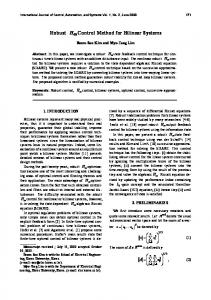
The proposed design method is exemplified here by producing a control system of a robot capable of covering a box with a lid – a brief and easy to follow example. This task requires an exteroceptor (e.g. an RGB-D camera) for locating the box and an impedance controlled effector (manipulator) to execute the task. However, it should be noted that those elements constitute only a part of the body of the Velma robot used in other experiments. The robot is composed of two KUKA LWR4+ arms equipped with two three-fingered Barrett grippers mounted on an active torso with an additional 2DOF active head (fig. 4).
Fig. 4: Two-handed robot Velma with an active torso and head The task of putting a lid on the box is realised in the following way. Assuming that the lid is already grasped and that the vision system has already approximately localised the box, the robot using position control (i.e. with high stiffness of the artificial spring in the impedance control law) carries the lid to a pose above the box. Then using slow motion it
Fig. 5: Inner structure of the agent atr representing the two-handed robot Velma
lowers the lid on the box decreasing the stiffness. Once contact is attained the manipulator induces small circular motions of the lid in the plane horizontal to the box top while exerting a force in the vertical direction. This should ensure that the lid pops onto the box. The agent atr , representing the Velma robot, contains three virtual effectors, forming the abstraction layer facilitating the control of the Velma body (fig. 5): etr,b controls the whole body posture, i.e. torso, head, left and right manipulator, while etr,lg and etr,rg control the postures of the left and right gripper fingers. The force-torque sensors (mounted in the joints of the KUKA arms) and tactile sensors (i.e. artificial skin of the Barrett grippers) are treated as proprioceptors, hence their measurements are processed by respective virtual effectors and used in motion generation. Additionally Velma possesses several exteroceptors gathering information about the state of the environment, e.g. location of the objects. The majority of those exteroceptors is located in the active head: two high-resolution digital cameras forming a stereo-pair and two Kinect sensors mounted vertically, thus providing data from complementary sectors in front of them. The information from the stereo-pair is aggregated by the rtr,sp virtual receptor, whereas rtr,kin processes RGB-D images from from the pair of Kinect sensors. There are also two virtual receptors rtr,lgc
and rtr,rgc , connected to cameras attached to the left and right gripper respectively. The exemplary task is very representative of the operations a service robot has to execute as it requires the combination of both visual and force sensing. To simplify the implementation of the task, an RGB-D camera instead of an RGB camera was mounted on one of the manipulator wrists. However, it was assumed that during task execution this manipulator will be immobile, hence this setup can be classified as SAC – Stand-Alone-Camera [39], with a known pose of the camera with respect to the robot base reference frame. Thus only one virtual effector, one virtual receptor and the control subsystem is presented here. The reduced structure of the agent atr is presented in fig. 6. For briefness of the presentation we describe only few selected behaviours of those subsystems. A. Real effector: KUKA LWR4+ The task of putting a lid on the box will be executed by the KUKA LWR4+, which is a serial, lightweight (16kG), redundant robot arm with seven degrees of freedom. Its characteristics (fig. 17) are similar to those of a human arm in terms of size, lifting capacity and manipulation capabilities, what enables it to safely operate in a human oriented environment. LWR4+ joints are not only equipped with motor encoders, but also with torque sensors. Motion can be commanded
is supplemented by a rotation angles around the frame axes (the aggregated angle-axis representation). The operator A transforms the above pose representation into a homogeneous matrix, and A−1 defines an inverse transformation: U A−1 (U (5) Q T) = Q r � � T The 6 × 1 column vector U r˙ = U v T , Uω T expressed with respect to (wrt) U represents the generalized velocity of a frame U moving relative to frame 0 (i.e. motion of U wrt 0 expressed in the coordinates of U treated as static).
A(U Q r) =
Fig. 6: The structure of the agent atr used in the example
both in the configuration (joint) space and operational space. Moreover, the desired torques can be set in joints. LWR4+ industrial controller can be connected to external controllers, particularly for research purposes. Thus the industrial controller is equipped with Fast Research Interface (FRI) [40] and uses Ethernet and UDP protocols, that enable reading the robot’s state and transmission of control commands. The contents of the input and output buffers of the real effector Etr,rm result from the requirements of the impedance control law in a version which includes a desired torque: κ
ι
U Q T,
U˙
r=
U 0 ˙ (U r)
(6)
It consists of linear velocity v and rotational velocity ω. The 6 × 1 column vector U F expresses a generalized force and consists of a 3 element force vector and a 3 element torque vector. In this case, force is applied to the origin of the coordinate frame U , and is expressed wrt the same frame. U Transformations U Q ξF and Q ξV transform generalized forces and velocities respectively, expressed wrt Q into those entities expressed wrt U , when both frames are affixed to the same rigid body:
ι
ι ˙ κ ¨m )+τdι (4) , qm , q τcκ+1 = ∗ Kιd (qdι − qm )+ ∗ Dιd q˙ m +f (qm
where κ – discrete time instants at which the control law (4) is computed by the real effector (∆κ ≈ 0.3ms), ι – discrete time instants at which some of the control law parameters are modified by the virtual effector (∆ι = 1ms), ∗ Kdι – joint stiffness vector, ∗ Ddι – joint damping vector, qdι – desired joint position vector, τdι – desired joint torque vector. Here and in the following the right subscript d stands for the desired value and m for the measured value, while c designates current or computed value. The virtual effector etr,b controls the behaviour of the real effector Etr,rm (i.e. influences its regulator) by providing through the Ey etr,b buffer to the x Etr,rm buffer the values of: ∗ Kdι , ∗ Ddι , qdι and τdι . The real effector Etr,rm obtains those values from the virtual effector etr,b , κ κ , velocity q˙ m and processes the measures the position qm ι ˙ ι ¨ι dynamics model f (qm , qm , qm ) to compute the control law (4). It also provides to etr,b via y Etr,rm and Ex etr,b the current value of the Jacobian matrix Jm , the current wrist pose in the form of a homogeneous matrix 0WTm along with the forces and torques measured in the wrist reference frame W Fm . The control law (4) is utilized by the external control loop of the real effector Etr,rm . The computed torque τcκ+1 is the regulator output, which is subsequently used as an input to the internal loop with the torque controller running with the frequency of tens of kHz. The structure of this regulator as well as its stability analysis were presented in [41]. B. Virtual effector representing the impedance controlled manipulator The operation of the virtual effector relies on several types of transformations, hence their general form must be explained first. Pose of the reference frame Q with respect to U can be expressed as either homogeneous matrix U Q T or a column vector U r. In the latter case, the position in Cartesian coordinates Q
U
F=
U Q F, Q ξF
U˙
r=
U Q˙ r Q ξV
(7)
In the case when free vectors are used (such as increments of position, orientation, velocity or force) there exists a need to express them wrt the frame, with an orientation other than the one in which they were initially expressed. In this case, one can use the C (U r˙) notation, in which the generalized velocity of frame U wrt 0 is expressed wrt frame C. For that purpose the transformation matrix ξ∗ is used [42]: C U˙
( r) =
C U˙ U ξ∗ r
(8)
Fig. 7: The transition function e,Eftr,b,1,1 of the virtual effector controlling the right manipulator using impedance control in operational space The example in the following text focuses on a behaviour realizing extended impedance control in the operational space.
This behaviour uses the transition function e,Eftr,b,1 , decomposed into e,Eftr,b,1,1 and e,Eftr,b,1,2 , each producing the value of a different component in the output buffer Ey etr,b . The function e,Eftr,b,1,1 computes τd in the following way (fig. 7). The pose error obtained from the control subsystem is transformed into the angle-axis representation: E
rd,m = A−1 ( E Td,m ).
(9)
The resulting vector E rd,m can be imagined as a sixdimensional spring stretched between the current and the desired end-effector pose. On the basis of the measured pose of the wrist (obtained through Ex etr,b ) and the known transformation between the wrist and the end-effector (obtained through xc etr,b ) the pose of the end-effector of the manipulator is determined: 0 0 W (10) E Tm = W Tm E T. The increment between the current pose of the end-effector and its pose memorised in the previous iteration of the virtual effector behaviour: E
Tm,p =
0 ( 0E Tp )−1 E Tm ,
(11)
enables the computation of the current velocity of the endeffector: A−1 ( E Tm,p ) E˙ (12) rm,p = ∆ι Next, a certain force is associated with the end-effector – it is called the computed force E Fc . It is computed on the basis of the length of the imaginary spring E rd,m , the velocity of the end-effector E r˙m,p , the desired effector stiffness Kd , the desired damping Dd and the desired force exerted on the environment E Fd : E
E
E˙
Fc = Kd rd,m + Dd rm,p +
E
Fd .
(13)
It is subsequently transformed into the wrist reference frame: W W E ξF
Fc =
W E E ξF Fc .
(14)
W E T.
is derived from Finally, the current value of the manipulator jacobian Jm is obtained from the real effector through Ex etr,b . This enables the computation of the desired values of joint torque, which is subsequently sent to the real effector: τd = (Jm )T W Fc . (15) The partial transition function responsible for computation of the desired joint torque is defined as: � E ι+1 τd ] := e,Eftr,b,1,1 e eιtr,b , xc eιtr,b , Ex eιtr,b , y etr,b [e � � −1 E (16) , (Jm )T W Td,m + E ξF Kd A � −1 0 −1 0 W A ( ( E Tp ) W Tm E T) + E Fd . +Dd ∆ι The ˜ symbol represents the place-holder within the buffer for storing the computed value. The joint regulators within the real effector should function as torque controllers with compensation of both gravity and partial dynamics of the
Fig. 8: The proprioceptive function effector
e,c
ftr,b,1 of the virtual
manipulator, so both the joint stiffness ∗ Kd and joint damping ∗ Dd vectors should be set to zero. In this case the value of qd is irrelevant, however it was also set to zero. Thus the partial transition function e,Eftr,b,1,2 computing the remaining real effector control parameters is trivial: E ι+1 e e y etr,b [ ∗ Kd , ∗ Dd ,
ed ] := q
e,E
ftr,b,1,2 () = [0, 0, 0].
(17)
where 0 = [0, . . . , 0]T is of an adequate dimension. Additionally, it is necessary to define the transition function of the virtual effector responsible for storing the current pose (which in the next step will be treated as the previous one): e ι+1 0 e etr,b [ E Tm ]
=
e,e
ftr,b,1 (xc eιtr,b ,
E ι x etr,b )
:=
0 W W Tm E T.
(18)
Also a proprioceptive transition function, responsible for conveying the state of the manipulator to the control subsystem, must be defined (fig. 8): e,c c ι+1 0 e Ee e ftr,b,1 (xc eιtr,b , Ex eιtr,b ) y etr,b [ E Tm , Fm , Jm ] := �−1 W W W 0 Fm , Jm ], = [W Tm E T, E ξF
=
(19) Hence, the transition function eftr,b,1 of the virtual effector is composed of: n o e ftr,b,1 , e,eftr,b,1 , e,cftr,b,1 , e,Eftr,b,1,1 , e,Eftr,b,1,2 . (20) The behaviour e Btr,b,1 is executed when the input buffer xc etr,b gets a new command from the control subsystem, i.e.: � e σ ftr,b,1 , ∃ xc eιtr,b . (21) It is a single step behaviour, thus: e τ ftr,b,1
, T RUE
(22)
and, moreover, no special error condition is assumed: e ε ftr,b,1
, FALSE.
(23)
e
Hence the Btr,b,1 behaviour is defined as: e
Btr,b,1 ,
e
� ε τ Btr,b,1 eftr,b,1 , eftr,b,1 , eftr,b,1 .
(24)
When the virtual effector is not triggered into activity by the control subsystem, it activates the default behaviour e Btr,b,0 responsible for holding the manipulator at stand still (i.e. it sends the same desired motor pose to the real effector in each step) as well as for providing the proprioceptive information to the control subsystem.
C. Virtual receptor representing an RGB-D camera The general method of object recognition utilises 3D object models. Those models are represented by two types of point clouds: dense colour cloud (used mainly during model generation for visualization purposes) and sparse cloud of features. The current implementation uses the SIFT features (Scale Invariant Feature Transform) [43], because they are still treated as the most robust and discriminative. An exemplary model is presented in fig. 9. Each model of an object is generated separately on the basis of a set of views taken off-line by looking at the object from different angles, whereas each of such views consist of: RGB image, depth map and automatically generated object mask (a binary image determining pixels belonging to the object or constituting the background).
(a)
(b)
(a)
(b)
Fig. 9: Exemplary 3-D point-based model: (a) dense RGB point cloud (b) sparse feature cloud
Fig. 11: Example of a 3-D point-based object hypothesis: (a) the exemplary scene (b) point cloud containing the scene and the object model along with the found correspondences
intrinsic parameters of the camera P. This operation results in the sparse cloud of SIFT features with Cartesian coordinates wrt the camera (Kinect) frame: � � C SIF T Cc = IC IcSIF T , IcD , P . (26) This cloud is subsequently compared with the feature clouds SIF T of all models stored in the virtual receptor memory CM . FLANN [44] is used as a procedure of feature matching: � � SIF T C SIF T . (27) Cc,M = FM C CcSIF T , CM
Fig. 10: Data flow diagram of the receptor-reading aggregation-function rftr,lkin,1 responsible for point-based object recognition The generation of the hypotheses by the reading aggregation function rftr,lkin,1 is presented in fig. 10. Initially a feature cloud is extracted out of the acquired RGB-D image obtained from the Kinect sensor via the Rx rtr,lkin buffer. Then SIFT features are extracted from the image IcRGB : � � IcSIF T = FE IcRGB . (25) Next their coordinates are transformed from the image to the Cartesian space. This is done using the knowledge of their distances from the sensor (the depth map IcD ) and known
It is an efficient implementation of the k nearest neighbours SIF T algorithm. Next the resulting set of correspondences C Cc,M is clustered: � � SIF T C Hc,M = CL C Cc,M . (28) This operation takes into account: (a) the model to which the given cluster of correspondences refers, (b) similarity of transformations between points forming the given cluster and the corresponding model points, as well as (c) the Cartesian distance between points belonging to the cluster. The idea is similar to the clustering method used by the MOPED framework [45], however enhanced with spatial information gained from the depth map. Finally, out of the set of hypotheses C Hc,M the one with the highest matching factor is selected and the object instance pose wrt camera frame is estimated: � C C Hc,M . (29) G Tc = PE The resulting pose is subsequently conveyed to the control subsystem through the yc rtr,lkin buffer. Thus the definition of
the transition function is as follows: � r ι R ι := r,cf�tr,lkin,1 rtr,lkin , � ��� � � rtr,lkin � , x� SIF T . , PE CL FM IC FE IcRGB , IcD , P , IM (30) The r Btr,lkin,1 behaviour is triggered by the presence of RGB-D image in the input buffer Rx rtr,lkin : � Fig. 12: Data flow diagram of the function c,eftr,1,1 involved r σ ι ftr,lkin,1 , ∃ Rx rtr,lkin , (31) in the execution of the PB-EOL-SAC visual servo lasts one step, thus: c ι+1 C e y rtr,lkin [G �Tc ]
r τ ftr,lkin,1
, T RUE
(32)
and no special error condition is assumed: r ε ftr,lkin,1
, FALSE.
(33)
The r Btr,lkin,1 behaviour is finally defined as: r
Btr,lkin,1 ,
r
Btr,lkin,1
r,c
� ε τ ftr,lkin,1 , rftr,lkin,1 , rftr,lkin,1 .
(34)
When there is no image to process, the virtual receptor enters the idle state (default behaviour r Btr,lkin,0 ) and waits until data will appear in the input buffer from the real receptor. D. Control subsystem The control subsystem of the Velma robot exhibits several behaviours: impedance control of the full body posture, realization of different types of grasps, tracking moving objects by cameras integrated with its active head using visual servoing, visually guided motion of its end-effectors. For brevity only two behaviours are presented: realization of visual servoing (used when the manipulator holding the lid approaches the box) and execution of a guarded motion (used for moving the lid towards the box until contact is detected). 1) Behaviour c Btr,1 : As it was mentioned before, the RGBD camera is mounted on the Velma’s second arm. However this arm is immobile during execution of the described task, so the resulting visual servo can be classified as PB-EOL-SAC (position based, not observing the end-effector pose, stand alone camera). The visual servo does not modify the contents of the memory. It also does not have to configure its virtual receptor or contact other agents. As its only purpose is to control its virtual effector, only the effector control function c,e ftr,1 has to be defined. Other transition functions (i.e. c,cftr,1 , c,T ftr,1 and c,rftr,1 ) are not required. As the buffer ye ctr,b has 3 components, thus c,eftr,1,1 is decomposed into 3 separate functions: c,eftr,1,1 , c,eftr,1,2 and c,eftr,1,3 , each computing the value of one of those 3 components. The effector control function c,eftr,1,1 (fig. 12) first computes the pose of the object of interest with respect to the endeffector reference frame. Thus it acquires the current object (goal) pose C G Tc from the virtual receptor rtr,lkin through r c . The control subsystem ctr holds in its memory c ctr the x tr,lkin 0 pose C T of the immobile camera (SAC) with respect to the global frame of reference. The current pose of the effector 0 e E Tm is obtained from the x ctr,b input buffer. Those three
elements are required for the computation of the pose of the object with respect to the end–effector reference frame: �−1 0 C E 0 (35) G Tc = E Tm C T G Tc . The desired displacement (offset) E G Td between the object and the end–effector is stored in memory c ctr – it represents the displacement of the gripper holding the lid wrt the box, so the lid will approximately fit the box (by executing a straight-line motion along the Z axis of the gripper). Taking into account the current and the desired displacement of the object and the end–effector the error is computed: �−1 E E Td,c = E . (36) G Tc G Td This displacement may be too large to be executed in one control step, hence a realizable increment is computed: E
Td,m = RC(E Td,c )
(37)
The regulator RC executes the Cartesian space regulation. It transforms the homogeneous matrix pose representation E Td,c into a vector V = [X, Y, Z, x, y, z, φ], where [X, Y, Z] represent the coordinates of Cartesian position, whereas the angle φ and axis [x, y, z] describe the orientation. The axis versor [x, y, z] is fixed for the given step, hence only the X, Y, Z, φ undergo regulation. The result is being clipped. Finally the results are retransformed into homogeneous matrix representation and subsequently sent to the virtual effector through ye ctr . Thus the definition of c,eftr,1,1 is: c,e e i+1 E e ftr,1,1 (c citr , xe citr,b , xr�citr,lkin ) y ctr,b [ �Td,c ] := � �−1 −1 0 C E , RC 0E Tm , C T G Tc G Td
,
(38)
The supplementary function c,eftr,1,2 computes the remaining parameters of the impedance-control law of the virtual effector, i.e. desired value of stiffness Kd , damping Dd and force Fd : e i+1 e e e y ctr,b [Kd , Dd , Fd ]
:= c,eftr,1,2 (c citr ) , [Kd,high , Dd,crit , 0], (39)
where Dd,crit is critical damping computed according to [46] and Kd,high represents stiffness of the end-effector motion along three translational and rotational directions, i.e.: Kd,high =
[Kd[x],high , Kd[y],high , Kd[z],high , Kd[ax ],high , Kd[ay ],high , Kd[az ],high ]T .
(40)
Additionally, the control subsystem sends to the virtual effector the pose of the end-effector wrt wrist the (which in the example is constant), so the third partial transition function is: e i+1 W e c [ T] := c,ef (c ci ) , W T. (41) y tr,b E
tr
tr,1,3
E
The behaviour terminates when the desired relative pose of the end-effector wrt the box is achieved: � � �−1 0 C c τ 0 E ftr,1 , (42) E Tm C T G Tc = G Td . Assuming that the behaviour does not require any special error conditions aborting its execution: c ε ftr,1
, FALSE.
(43)
c
Thus the behaviour Btr,1 is defined as follows: c
Btr,1 ,
c
Btr,1 (c,eftr,1,1 ,
c,e
ftr,1,2 ,
c,e
ε τ ftr,1,3 , cftr,1 , cftr,1 ).
(44)
2) Behaviour c Btr,2 : The second behaviour starts when the gripper holds the lid in a pose enabling the robot to put it on a box This is done by moving the lid along a straight line defined by the Z axis of the gripper frame (the displacement c represented as E G Td in the Btr,1 behaviour). The end-effector moves with a constant, small velocity vd[z] along that axis: � c,e e i+1 E e ftr,2,1 (c citr ) , A−1 0, 0, vd[z] ∆i, 0, 0, 0 , y ctr,b [ Td,c ] := (45) where ∆i represents the duration of a single step of behaviour. The impedance parameters are set to make the manipulator compliant, hence stiffness is low and damping is set as critical. As no extra force has to be exerted on the box it is set to zero: e i+1 e e e ,D , 0]. (46) c [Kd , Dd , Fd ] := c,ef (c ci ) , [K y tr,b
tr
tr,2,2
d,low
tr
tr,2,3
E
The forces and torques exerted by the end-effector, obtained from the virtual effector through the xe ctr,b are used to detect contact with the box: � c τ (48) ftr,2 , Fm[z] ≥ Fm[z],limit , where Fm[z],limit is the threshold force. Again it was assumed that error condition will not occur, hence: c ε ftr,2
, FALSE,
(49)
c
so the definition of behaviour Btr,2 is: c
Btr,2 ,
c
Btr,2 (c,eftr,2,1 ,
c,e
ftr,2,2 ,
c,e
Manipulation is based both on touch and sight, thus visual servoing has been extensively studied. As a result of work on classification and taxonomy of structures of visual servos [39] diverse embodied agents utilizing both immobile and mobile cameras [38], [51] as well as the methods of their testing and verification were developed. C. Robot playing checkers The presented design method was also used for the development of several robotic systems combining force control and visual servoing. One such system was able to play the game of checkers with a human opponent [52]. The system consisted of two agents: an agent controlling a modified IRp-6 manipulator with a camera integrated with a two-finger gripper (fig. 13) and an agent using artificial intelligence to deduce the robot’s ply. Visual servoing was utilized to approach a pawn while force control was used to grasp it. Moreover, experiments with parallel visual force control [53] were also conducted.
d,crit
The control subsystem has also to send the transformation between the wrist and end-effector frame: e i+1 W e c [ T] := c,ef (c ci ) , W T. (47) y tr,b E
B. Visual servoing
ε τ ftr,2,3 , cftr,2 , cftr,2 ).
(50)
IV. E XAMPLES OF ROBOT SYSTEMS AND THEIR TASKS A. Force control Force sensing (touch) is paramount to the control of the robot–environment interaction. The presented specification method was used to develop several robot systems utilizing position-force control, i.e. classical force-control benchmarks such as following of an unknown contour or rotating a crank [47], copying drawings by a single- [48] and a two-arm robot [49], as well as a dual-arm robot system acting as a haptic device [50].
Fig. 13: Gripper of the modified IRp-6 manipulator above the checkers board D. Rubik’s cube puzzle Another, even more sophisticated system, that had been developed by the presented design method, was a dual armsystem solving a Rubik’s cube puzzle (fig. 14) [54], [55]. At first sight it might seem that solving the Rubik’s cube puzzle is an easy task for a robot, but in reality it is not so. The robot has to acquire a very metamorphic object (a Rubik’s cube has trillions of appearances, there are no assumptions as to the background or lighting conditions). It requires two hands to rotate its faces, and moreover, the faces can jam if not aligned properly (this requires position-force control). The cube is handed to the robot by a human, thus neither its location is known a priori, nor the cube is static when being acquired (this requires visual servoing). Once grasped, the state of the cube must be identified, and out of that information a plan must be deduced, i.e. the sequence of rotations of the faces leading to the state in which each of the faces contains tiles of the same colour (this requires artificial intelligence search algorithms for solving the puzzle). It is important that the plan of actions
Fig. 14: Manipulation of the Rubik’s cube
cannot be produced off-line – it must be defined while the task is being executed, as the initial state of the cube is not known in advance. Each of the above steps cannot take too long, thus time-efficient algorithms must be utilized. Above all, all of those capabilities must be integrated into a single system. The two-handed system contained: two kinematically modified IRP-6 robots, special purpose control hardware (which was subsequently modified to its current version [56]), and shape grippers [57]. In particular, indirect force control was used to prevent face jamming during cube manipulation [58], [59]. This work was the primary benchmark for both the robotic system formal specification method and the MRROC++ robot programming framework [42]. E. Active vision
Fig. 15: The modified IRp-6 manipulator equipped with a camera observing a blue ball and its flat imitation from different angles
G. A robot based reconfigurable fixture Automotive and aircraft industries commonly use components made of thin metal or composite sheets in their products. To machine those deformable parts devices for locating, constraining, and providing stable support are required, i.e. fixtures. Standard fixtures are large molds reproducing
The presented design method was also utilized for the development of several agents using active vision for purposeful acquisition of visual information regarding their surroundings. In particular a single robot system able to distinguish between a simple convex object and its flat imitation [60] was developed (fig. 15). Yet another example of active vision is a system proactively recognizing operator hand postures (fig. 16), described in details in [61]. F. Velma opening the doors One of the tasks that the Velma robot was put to was opening the doors. This is a capability one would expect of a service robot. This task can be realized in various ways. If the connection of the manipulator end–effector to the doors is rigid, there is no need to estimate the kinematics of the doors (fig. 17) [62]. However the majority of methods is based on the door kinematics estimation, because for common grippers and door handles a stiff connection cannot be guaranteed. Here the tests were conducted using impedance controlled manipulator with torque controllers in its joints [46]. The pose of the door handle was obtained by using cameras mounted in the active head (fig. 4) [63] to extract the door features (fig. 18) [64]. The BarretHand gripper was used to grasp the handle [65].
(a)
(b)
(c)
(d)
Fig. 16: Stages of the active hand pose recognition: (a-c) approach the hand-like object, (d) pose identification
while the other relocates itself in such a way as to precede the working tool. Mobile base motion plan and sequences of manipulator postures are automatically generated off-line based on the CAD/CAM model of the workpiece [70]. The control system, taking in the thus generated task plan as input, was designed by using the presented approach. A multiagent system operating in an industrial environment resulted. The supervisory agent employed a Petri net to coordinate the actions of the embodied agents [71]. H. Box pushing
(a)
(b)
Fig. 17: KUKA LWR arm with the characteristic coordinate frames and transformations between them, while opening cabinet doors
the shape to be supported. Such fixtures are dedicated to a workpiece, so summarily they are numerous, expensive and not reconfigurable. Thus, a system consists of a set of mobile platforms carrying parallel type manipulators equipped with deformable heads was built to act as a reconfigurable fixture [66]–[69] (fig. 19). The heads support large flexible workpieces in the vicinity of machining. When the location of machining changes, the supporting robots translocate themselves to this location. The machined workpieces have complex spacial geometry. Drilling requires static placement of supporting robots, while milling necessitates their continuous relocation during machining. In the latter case two heads consecutively relocate and affix themselves to the supported thin metal sheet, so that one of them supports the workpiece
Fig. 18: Velma robot localizing the door features using its prototype active head
The presented approach has also been applied to the design of behavioural controllers for robots executing a joint transportation task [72]. In that example the robots observed the effects of the activities of other robots on the environment (stigmergy) [73]. Each mobile robot acted independently, knowing only the goal that the box should reach. Relying on the observation of the behaviour of the box the robots reacted in such a way that the box finally reached the goal. Each robot used 4 concurrently acting partial transition functions. The results of their computations were composed using weighted superposition. Each partial transition function used feedback to correct the behaviour of the box, i.e. inducing a motion in the box, locating the robot at the box corner, keeping the front of the robot towards the goal and keeping the front of the box facing the target.
Fig. 19: Robot based reconfigurable fixture and the CNC machine
V. C ONCLUSIONS The presented method of designing robot control systems is based on a general architecture (universal model) of an embodied agent, which is subsequently tailored to the required hardware of the system and the task it has to execute. The method requires the definition of the structure of the communication buffers and internal memory of the subsystems of the agent. Those buffers are used as arguments of transition functions that define the behaviours of subsystems. All behaviours are based on the same pattern presented in fig. 2. The thus defined behaviours are assembled into the overall task of a subsystem by defining an adequate FSM. The general task is realised by the control subsystem. Usually the enumerated design steps are executed iteratively refining the specification. Once the specification is detailed enough it is used for the implementation of the required system. The design method on the one hand imposes a certain domain specific architectural structure, but on the other is not constraining with respect to a control paradigm. Multi-tire architectures can be composed by assembling agents into layers. Specific agents or their subsystems can be reactive or deliberative as well as hybrid. The level of abstraction depends on the definition of data structures contained in the buffers. The paper has presented both an example of such a specification for a simple robot system and the set of systems that have been designed using this approach. The diversity of those systems, both in terms of the hardware utilised and the executed tasks enables us to conclude that this design method is general enough to be applied to any robotic system. ACKNOWLEDGMENT This project was financially supported by the National Centre for Research and Development grant no. PBS1/A3/8/2012. Tomasz Winiarski is supported by EU in the framework of the European Social Fund through the Warsaw University of Technology Development Programme. R EFERENCES [1] S. Kaisler, Software Paradigms. Wiley Interscience, 2005. [2] C. Blume and W. Jakob, PASRO: Pascal for Robots. Springer–Verlag, 1985. [3] ——, “Programming languages for industrial robots,” 1986. [4] V. Hayward and R. P. Paul, “Robot manipulator control under unix RCCL: A robot control C library,” International Journal of Robotics Research, vol. 5, no. 4, pp. 94–111, Winter 1986. [5] P. Corke and R. Kirkham, “The ARCL robot programming system,” 14–16 July 1993, pp. 484–493. [6] J. Lloyd, M. Parker, and R. McClain, “Extending the RCCL Programming Environment to Multiple Robots and Processors,” 1988, pp. 465– 469. [7] V. Hayward and S. Hayati, “Kali: An environment for the programming and control of cooperative manipulators,” in 7th American Control Conference, 1988, pp. 473–478. [8] P. Backes, S. Hayati, V. Hayward, and K. Tso, “The kali multi–arm robot programming and control environment,” in NASA Conference on Space Telerobotics, 1989, pp. 89–7. [9] V. Hayward, L. Daneshmend, and S. Hayati, “An overview of KALI: A system to program and control cooperative manipulators,” in Advanced Robotics, K. Waldron, Ed. Berlin: Springer–Verlag, 1989, pp. 547–558. [10] A. Nilakantan and V. Hayward, “The Synchronisation of Multiple Manipulators in Kali,” Robotics and Autonomous Systems, vol. 5, no. 4, pp. 345–358, 1989.
[11] B. P. Gerkey, R. T. Vaughan, K. Støy, A. Howard, G. S. Sukhatme, and M. J. Mataric, “Most Valuable Player: A Robot Device Server for Distributed Control,” in Proceedings of the IEEE/RSJ International Conference on Intelligent Robots and Systems (IROS), 2001, pp. 1226– 1231. [12] T. Collett, B. MacDonald, and B. Gerkey, “Player 2.0: Toward a practical robot programming framework,” in Proceedings of the Australasian Conference on Robotics and Automation (ACRA), December 2005. [Online]. Available: http://www.ai.sri.com/ gerkey/papers/acra2005.pdf [13] R. T. Vaughan and B. P. Gerkey, “Reusable robot software and the Player/Stage project,” in Software Engineering for Experimental Robotics, ser. Springer Tracts in Advanced Robotics, D. Brugali, Ed. Springer, 2007, vol. 30, pp. 267–289. [14] H. Bruyninckx, “Open robot control software: the orocos project,” in International Conference on Robotics and Automation (ICRA), vol. 3. IEEE, 2001, pp. 2523–2528. [15] ——, “The real-time motion control core of the OROCOS project,” in Proceedings of the IEEE International Conference on Robotics and Automation. IEEE, September 2003, pp. 2766–2771. [16] P. Fitzpatrick, G. Metta, and L. Natale, “Towards long-lived robot genes,” Robotics and Autonomous Systems, vol. 56, no. 1, pp. 29–45, 2008. [17] G. Metta, P. Fitzpatrick, and L. Natale, “YARP: Yet Another Robot Platform,” International Journal on Advanced Robotics Systems, vol. 3, no. 1, pp. 43–48, 2006. [18] A. Brooks, T. Kaupp, A. Makarenko, S. Williams, and A. Orebäck, “Orca: A component model and repository,” in Software Engineering for Experimental Robotics, ser. Springer Tracts in Advanced Robotics, D. Brugali, Ed. Springer, 2007, vol. 30, pp. 231–251. [19] A. Brooks, T. Kaupp, A. Makarenko, S. Williams, and A. Orebäck, “Towards component-based robotics,” in IEEE/RSJ International Conference on Intelligent Robots and Systems (IROS’05), August 2005, pp. 163–168. [20] M. Quigley, B. Gerkey, K. Conley, J. Faust, T. Foote, J. Leibs, E. Berger, R. Wheeler, and A. Ng, “ROS: an open-source Robot Operating System,” in Proceedings of the Open-Source Software workshop at the International Conference on Robotics and Automation (ICRA), 2009. [21] C. Zieli´nski, “The MRROC++ system,” in Proceedings of the First Workshop on Robot Motion and Control, RoMoCo’99, June 1999, pp. 147–152. [22] C. Zieli´nski, W. Szynkiewicz, K. Mianowski, and K. Nazarczuk, “Mechatronic design of open-structure multi-robot controllers,” Mechatronics, vol. 11, no. 8, pp. 987–1000, November 2001. [23] C. Zieli´nski, “Formal approach to the design of robot programming frameworks: the behavioural control case,” Bulletin of the Polish Academy of Sciences – Technical Sciences, vol. 53, no. 1, pp. 57–67, March 2005. [24] ——, “Systematic approach to the design of robot programming frameworks,” in Proceedings of the 11th IEEE International Conference on Methods and Models in Automation and Robotics (on CD). Technical University of Szczecin, 29 August – 1 September 2005, pp. 639–646. [25] ——, “Transition-function based approach to structuring robot control software,” in Robot Motion and Control, ser. Lecture Notes in Control and Information Sciences, K. Kozłowski, Ed. Springer-Verlag, 2006, vol. 335, pp. 265–286. [26] D. Brugali, G. S. Broten, A. Cisternino, D. Colombo, J. Fritsch, B. Gerkey, G. Kraetzschmar, R. Vaughan, and H. Utz, “Trends in robotic software frameworks,” in Software Engineering for Experimental Robotics, D. Brugali, Ed. Springer-Verlag, 2007, pp. 259–266. [27] J. Fritsch and S. Wrede, “An integration framework for developing interactive robots,” in Software Engineering for Experimental Robotics, D. Brugali, Ed. Springer–Verlag, 2007, pp. 291–305. [28] A. Bonarini, M. Matteucci, and M. Restelli, “Mrt: Robotics off-theshelf with the modular robotic toolkit,” in Software Engineering for Experimental Robotics, D. Brugali, Ed. Springer–Verlag, 2007, pp. 345–364. [29] I. Nesnas, “The CLARAty project: Coping with hardware and software heterogenity,” in Software Engineering for Experimental Robotics, D. Brugali, Ed. Springer–Verlag, 2007, pp. 9–30. [30] R. A. Brooks, “A robust layered control system for a mobile robot,” IEEE Journal of Robotics and Automation, vol. 2, no. 1, pp. 14–23, 1986. [31] R. C. Arkin, Behavior-Based Robotics. MIT Press, 1998. [32] A. Cisternino, D. Colombo, V. Ambriola, and M. Combetto, “Increasing decoupling in the robotics4.net framework,” in Software Engineering for
[33] [34]
[35] [36]
[37] [38] [39] [40]
[41]
[42] [43] [44] [45]
[46] [47]
[48]
[49] [50]
[51]
[52]
[53]
Experimental Robotics, D. Brugali, Ed. Springer–Verlag, 2007, pp. 307–324. B. Dittes and C. Goerick, “A language for formal design of embedded intelligence research systems,” Robotics and Autonomous Systems, vol. 59, no. 3–4, pp. 181–193, March–April 2011. D. Brugali, A. Agah, B. MacDonald, I. Nesnas, and W. Smart, “Trends in robot software domain engineering,” in Software Engineering for Experimental Robotics, D. Brugali, Ed. Springer–Verlag, 2007, pp. 3–8. D. Brugali, “Stable analysis patterns for robot mobility,” in Software Engineering for Experimental Robotics, D. Brugali, Ed. Springer– Verlag, 2007, pp. 9–30. M. Klotzbücher, R. Smits, H. Bruyninckx, and j. De Schutter, “Reusable hybrid force-velocity controlled motion specifications with executable domain specific languages,” in 2011 IEEE/RSJ International Conference on Intelligent Robots and Systems, September 25-30, 2011, San Francisco, USA, 2011, pp. 5684–4689. A. Kleppe, Software Language Engineering: Creating Domain-Specific Languages Using Metamodels. Addison-Wesley, 2009. T. Kornuta and C. Zieli´nski, “Robot control system design exemplified by multi-camera visual servoing,” Journal of Intelligent & Robotic Systems, pp. 1–25, 2013. M. Staniak and C. Zieli´nski, “Structures of visual servos,” Robotics and Autonomous Systems, vol. 58, no. 8, pp. 940–954, 2010. G. Schreiber, A. Stemmer, and R. Bischoff, “The fast research interface for the kuka lightweight robot,” in IEEE ICRA Workshop on Innovative Robot Control Architectures for Demanding (Research) Applications– How to Modify and Enhance Commercial Controllers. Anchorage, 2010. A. Albu-Schäffer, C. Ott, and G. Hirzinger, “A unified passivity-based control framework for position, torque and impedance control of flexible joint robots,” The International Journal of Robotics Research, vol. 26, no. 1, pp. 23–39, 2007. C. Zieli´nski and T. Winiarski, “Motion generation in the MRROC++ robot programming framework,” International Journal of Robotics Research, vol. 29, no. 4, pp. 386–413, 2010. D. G. Lowe, “Distinctive image features from scale-invariant keypoints,” International journal of computer vision, vol. 60, no. 2, pp. 91–110, 2004. M. Muja and D. G. Lowe, “Fast approximate nearest neighbors with automatic algorithm configuration.” in VISAPP (1), 2009, pp. 331–340. A. Collet, M. Martinez, and S. S. Srinivasa, “The MOPED framework: Object Recognition and Pose Estimation for Manipulation,” The International Journal of Robotics Research, vol. 30, no. 10, pp. 1284–1306, 2011. T. Winiarski and K. Banachowicz, “Opening a door with a redundant impedance controlled robot,” Robot Motion & Control (RoMoCo), 9th Workshop on, pp. 221–226, 2013. C. Zieli´nski, W. Szynkiewicz, and T. Winiarski, “Applications of MRROC++ robot programming framework,” in Proceedings of the 5th International Workshop on Robot Motion and Control, RoMoCo’05, Dymaczewo, Poland, K. Kozłowski, Ed., June, 23–25 2005, pp. 251– 257. T. Winiarski and C. Zieli´nski, “Implementation of position–force control in MRROC++,” in Proceedings of the 5th International Workshop on Robot Motion and Control, RoMoCo’05, Dymaczewo, Poland, June, 23– 25 2005, pp. 259–264. C. Zieli´nski and T. Winiarski, “General specification of multi-robot control system structures,” Bulletin of the Polish Academy of Sciences – Technical Sciences, vol. 58, no. 1, pp. 15–28, 2010. T. Winiarski and C. Zieli´nski, “Specification of multi-robot controllers on an example of a haptic device,” in Robot Motion and Control (LNCiS) Lecture Notes in Control & Information Sciences, K. Kozłowski, Ed., vol. 396. Springer Verlag London Limited, 2009, pp. 227–242. C. Zieli´nski, T. Kornuta, and M. Bory´n, “Specification of robotic systems on an example of visual servoing,” in 10th International IFAC Symposium on Robot Control (SYROCO 2012), vol. 10, no. 1, 2012, pp. 45–50. T. Kornuta, T. Bem, and T. Winiarski, “Utilization of the FraDIA for development of robotic vision subsystems on the example of checkers’ playing robot,” Machine GRAPHICS & VISION, vol. 4, pp. 495–520, 2011. M. Staniak, T. Winiarski, and C. Zieli´nski, “Parallel visual-force control,” in Proceedings of the IEEE/RSJ International Conference on Intelligent Robots and Systems, IROS ’08, 2008.
[54] C. Zieli´nski, W. Szynkiewicz, T. Winiarski, M. Staniak, W. Czajewski, and T. Kornuta, “Rubik’s cube as a benchmark validating MRROC++ as an implementation tool for service robot control systems,” Industrial Robot: An International Journal, vol. 34, no. 5, pp. 368–375, 2007. [55] W. Szynkiewicz, C. Zieli´nski, W. Czajewski, and T. Winiarski, “Control Architecture for Sensor-Based Two-Handed Manipulation,” in CISM Courses and Lectures – 16th CISM–IFToMM Symposium on Robot Design, Dynamics and Control, RoManSy’06, June 20–24, T. Zieli´nska and C. Zieli´nski, Eds., no. 487. Wien, New York: Springer, 2006, pp. 237–244. [56] M. Wal˛ecki, K. Banachowicz, and T. Winiarski, “Research oriented motor controllers for robotic applications,” in Robot Motion and Control 2011 (LNCiS) Lecture Notes in Control & Information Sciences, K. Kozłowski, Ed., vol. 422. Springer Verlag London Limited, 2012, pp. 193–203. [57] C. Zieli´nski, T. Winiarski, K. Mianowski, A. Rydzewski, and W. Szynkiewicz, “End-effector sensors role in service robots,” in Robot Motion and Control 2007 (LNCiS) Lecture Notes in Control & Information Sciences, K. Kozłowski, Ed. Springer Verlag London Limited, June, 11–13 2007, pp. 401–413. [58] T. Winiarski and A. Wo´zniak, “Indirect force control development procedure,” Robotica, vol. 31, pp. 465–478, 4 2013. [59] T. Winiarski and M. Wal˛ecki, “Motor cascade position controllers for service oriented manipulators,” in Recent Advances in Automation, Robotics and Measuring Techniques, ser. Advances in Intelligent Systems and Computing (AISC), R. Szewczyk, C. Zieli´nski, and M. Kaliczy´nska, Eds. Springer, 2014, pp. 533–542. ˙ [60] T. Kornuta and Łukasz Zmuda, “Specification of the structure and behaviours of a robotic system able to determine object convexity,” in 18th IEEE International Conference on Methods and Models in Automation and Robotics, MMAR’2013. IEEE, 2013, pp. 350–355. [61] T. Kornuta and C. Zieli´nski, “Behavior-based control system of a robot actively recognizing hand postures,” in 15th IEEE International Conference on Advanced Robotics, ICAR, June 2011, pp. 265–270. [62] T. Winiarski, K. Banachowicz, and M. Stefa´nczyk, “Safe strategy of door opening with impedance controlled manipulator,” Journal of Automation Mobile Robotics and Intelligent Systems, vol. 7, no. 4, pp. 21–26, 2013. [63] M. Wal˛ecki, M. Stefa´nczyk, and T. Kornuta, “Control system of the active head of a service robot exemplified on visual servoing,” in Robot Motion and Control (RoMoCo), 9th Workshop on, 2013, pp. 48–53. [64] M. Stefa´nczyk and M. Wal˛ecki, “Localization of essential door features for mobile manipulation,” in Recent Advances in Automation, Robotics and Measuring Techniques, ser. Advances in Intelligent Systems and Computing (AISC). Springer, 2014, pp. 487–496. [65] T. Winiarski, K. Banachowicz, and D. Seredy´nski, “Multi-sensory feedback control in door approaching and opening,” Inteligent Systems (accepted), 2014. [66] L. Xiong, R. Molfino, and M. Zoppi, “Fixture layout optimization for flexible aerospace parts based on self-reconfigurable swarm intelligent fixture system,” International Journal of Advanced Manufacturing Technology, pp. 1305–1313, 2012. [67] L. de Leonardo, M. Zoppi, X. Li, D. Zlatanov, and R. Molfino, “Swarmitfix: A multi-robot-based reconfigurable fixture,” Industrial Robot, pp. 320—-328, 2013. [68] C. Zieli´nski, W. Kasprzak, T. Kornuta, W. Szynkiewicz, P. Trojanek, M. Wal˛ecki, T. Winiarski, and T. Zieli´nska, “Control and programming of a multi-robot-based reconfigurable fixture,” Industrial Robot: An International Journal, vol. 40, no. 4, pp. 329–336, 2013. [69] C. Zieli´nski, T. Kornuta, P. Trojanek, T. Winiarski, and M. Wal˛ecki, “Specification of a multi-agent robot-based reconfigurable fixture control system,” Robot Motion & Control 2011 (Lecture Notes in Control & Information Sciences), vol. 422, pp. 171–182, 2012. [70] T. Zieli´nska, W. Kasprzak, W. Szynkiewicz, and C. Zieli´nski, “Path planning for robotized mobile supports,” Journal of Mechanism and Machine Theory, vol. 78, pp. 51–64, 2014. [71] P. Trojanek, T. Kornuta, and C. Zieli´nski, “Design of asynchronously stimulated robot behaviours,” in Robot Motion and Control (RoMoCo), 9th Workshop on, K. Kozłowski, Ed., 2013, pp. 129–134. [72] C. Zieli´nski and P. Trojanek, “Stigmergic cooperation of autonomous robots,” Journal of Mechanism and Machine Theory, vol. 44, pp. 656– 670, April 2009. [73] E. Bonabeau, M. Dorigo, and G. Theraulaz, Swarm Intelligence: From Natural to Artificial Systems. New York, Oxford: Oxford University Press, 1999.