Unsupervised training methods and a guided graphical user interface makes ... safety critical parts is applied as a standard particularly in automotive industry. ..... The software is intelligent, i.e. the user gets hints for useful parameters and the.
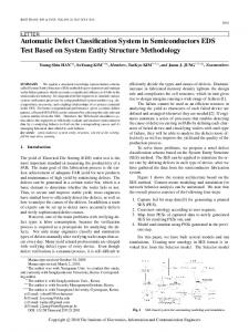
A THIRD GENERATION AUTOMATIC DEFECT RECOGNITION SYSTEM F. Herold1, K. Bavendiek2, and R. Grigat1 1 Hamburg University of Technology, Hamburg, Germany; 2 YXLON International X-Ray GmbH, Hamburg, Germany Abstract: Ten years of development in the field of fully automatic X-ray inspection systems for Non-Destructive Testing (NDT) have yielded new technologies in image processing hardware and software. For aluminum castings a hundred percent inspection of safety critical parts has become a standard particularly in automotive industry. Today “Automatic Defect Recognition” (ADR) systems are convincing due to their reliability and efficiency. Since the first generation of ADR systems has been started with a so-called “Golden Image” approach the second generation also took into account that systematic defects could happen, e.g. tolerances in positioning or regular structures. But still several parameters had to be adjusted individually by image processing experts in a long setup phase, i.e. it took weeks of adjusting time. Nowadays a third generation of ADR systems has evolved. These have fully automated analysis and classification methods for ADR. In this article we will introduce a third generation ADR system, which is ideally suited to find and classify different kinds of defect types reliably and fast. Unsupervised training methods and a guided graphical user interface makes the system easy to use even by non-experts. Especially defects that are 1. very small with very low contrast in the X-ray image or 2. big with low intensity that “hide“ behind the structure of the part can be found with a high reliability. Moreover the automatic classification of defect types allows direct process feedback to the casting process, i.e. the test result is much more detailed than a good/bad decision. Introduction: Fully automatic defect recognition (ADR) systems for non-destructive testing (NDT) have been used for the last ten years due to their reliability and efficiency. For aluminum castings a hundred percent inspection of safety critical parts is applied as a standard particularly in automotive industry. The well-known ADR systems can be divided into two stages of development. A third generation is approaching. Basically all ADR systems are using the same procedure to recognize the defects automatically (see figure 1). Starting from the current digital X-ray image to be analyzed (original image) and assuming that an ideal image is known a difference image of both is computed directly. A suitable segmentation algorithm (e.g. threshold binarization) is used to process a binary image that depicts potential casting defects.
Ideal image
Original image
X-ray image with defects
Threshold Difference image Figure 1: Automatic defect recognition.
Binary image
The methods differ in the way how the ideal image is received and how the recognized potential defects are interpreted. The first generation uses a so-called “Golden Image” approach. With this an X-ray image of a test object that corresponds to the specification (a good image) is applied as an ideal image of the automatic defect recognition. Figure 2 illustrates some artifacts of this method.
Figure 2: Images with translation. The difference image contains major edges. A minor deviation because of tolerances in positioning yields to major edges in the difference image, i.e. so-called pseudo defects are found by the ADR system. Translational and rotational distortion of the test object can be corrected by a similarity transform on the X-ray image. This correction is called image registration. On the other hand tilted test objects induce new intensity distributions in the X-ray image. Because of this pseudo defects are still recognized in the difference image (see figure 3).
Figure 3: Difference image of X-ray images of tilted object. The methods of the first generation are not used anymore. Artifacts make them unusable for batch testing systems because of tolerances • in positioning (e.g. due to the wear out of the gripper) or • of the part (e.g. burrs, deformation). The second generation also takes into account that systematic defects as described above could appear. These ADR systems are using special image processing filters to create an ideal image [1, 2, 4]. The setup phase of such a system turns out to be a long period of adjusting several parameters, which is a job of weeks for experienced image processing experts [2]. First of all the image acquisition has to be optimized by adjusting the contrast for example. Then all test regions of the dedicated test object have to be defined in the X-ray image in connection with the test specification. Here the allowed tolerances are defined for special regions of the test object. For each region a predefined image processing filter or a combination of several filters is chosen depending on the test object itself or on the expected defect type. Generally an image processing filter is composed of a sliding window that is linked to a mathematical function (see figure 4). The sliding window also contains the values of the neighbor pixel of the dedicated central pixel in an array. Processing the mathematical function yields to a new value for the central window element or pixel respectively. The function is freely selectable and usually depends on the experience of the image processing expert. In case the sliding window (filter kernel) is smaller than the defects to be detected, the defects cannot be found. The larger the filter kernel is, the longer its computation takes.
Central pixel
Sliding window
f Function Image
Filtered image
Figure 4: Sliding window of an image filter method. Furthermore the image processing filters can be divided into filter methods 1. with a-priori information and 2. without a-priori information concerning the test object. Filter methods without a-priori information [4] have the advantage that the ideal image is computed only under the assumption that the test object is locally smooth. High spatial frequencies point on potential defects. On the other hand a large disadvantage is that a missing part of the test object cannot be recognized. But this has to be expected,
because there is no prior knowledge about the structure of the test object. Moreover sharp edges also have high spatial frequencies in the X-ray image and are mistaken for a defect. They are called regular structures and are also found in good images. Methods with a-priori information concerning the test object are able to learn these regular structures by comparing them with their knowledge about good images. Also missing parts of the object are detected. But therefore training is required and its result depends on the robustness against the tolerances already mentioned above. Today there are two competing methods for minimization of the pseudo defect rate: 1. using a positive list or 2. using a negative list. Using a positive list means that all possible defect types or shapes are known in advance. Potential defects are not realized, if they differ too much from a list of templates. There is always the latent risk to miss a serious defect in the test object. The negative list contains the trained regular structures. Here the assumption is valid that defects have an arbitrary shape. Only regular structures, which also can be found in good images, will be distinguished from the potential defects. After one of these defect verification methods the remaining defects in the list of potential defects are compared to the test specification. The result is a good/bad decision for the current test object, i.e. the ADR systems are securing that in no case a real defect will be ignored. But there are still a lot of rejects because of pseudo defects, which result from the uncertainty of this coarse decision method. The third generation of ADR systems ties up to the reliability and efficiency of the preceding generation. At the same time the hardware has been improved substantially. Due to new flat panel detectors X-ray images can be acquired with higher resolution at higher frame rates and also at higher levels of image quality. Therefore even defects, which were a big challenge for older systems, like defects that are 1. very small with very low contrast in the X-ray image or 2. big with low intensity that “hide“ behind the structure of the part can be found with a high reliability. The third generation ADR system presented here adapts itself to fulfill the needs of the user. Fully automated analysis and classification methods perform the most of the time-consuming parameter adjusting of former systems (see [2, 3]). The defect recognition comprises of the following essential steps: 1. setup of the test specification (setup phase), 2. unsupervised training for ADR (setup phase), 3. automatic defect recognition (online in a batch testing system), 4. classification (online in a batch testing system with feedback for casting process optimization). A guided graphical user interface (GUI) aids the user during the setup step of the test specification. A tree view offers the user an overview which steps are following and how far he has reached until now. Hereby it is guaranteed that no step is missing. Useful default values for the user are given within clear input forms. Likewise the system is easy to use even by non-experts. Here a fully automated filter method with a-priori information concerning the test object is used to minimize the time need of the analysis. The so-called Trained Median Filter (TMF) is a non-linear and non-local filter (see figure 5). Non-linear is related to the chosen analysis method. Essentially a median function is applied to the filter kernel. For a pixel at center i with reference points Rr the following applies
~ X i = median( X i , Rr )
with i ∈ [1Κ N ] and r ∈ [1Κ R ]
(1)
for N number of pixels and R number of reference points belonging to the central pixel. Non-local describes the choice of reference points of the filter kernel. Here it is not a direct neighborhood, but the pixels have to be correlated, i.e. all reference points are pixels with a similar behavior like the central pixel. Hence
the filter kernel is not restricted to an adjacent area that limits the size of recognizable defects. The kernel can be spread over the whole X-ray image [2, 3].
R
R X
R
Median R
Figure 5: Trained Median Filter (TMF). The TMF uses pre-registered X-ray images by default. Several good images (e.g. 50) are analyzed in an unsupervised training step to find characteristic variances of the ADR system depending on the type of the test object. The results are stored into a knowledge base. Moreover the training is not time critical, because it is only needed once per test object. Today the training takes less than half a minute. For 51 X-ray images at 512 x 512 x 16 bit the computation time took about 6 seconds at an Intel Pentium IV, 2GHz (see [3]). During the online process only the new ideal image is processed by evaluating the median (1) with the aid of the knowledge base. For only four reference points this is done in a fraction of a second (see [3]). After defect verification by a negative list the defects are classified. Here also defects that are below the test specification are processed. more dense
inclusion single shrinkage
less dense
shrinkage
shrinkage cavity
gas bubble
shrinkage sponge
single gas bubble
porosity
surface defect
dragmarks
dragging, soldering
Figure 6: Decision tree. Figure 6 depicts a decision tree, which relates to the ASTM E155 classification of casting defects. The first layer distinguishes between less or more dense defects of the spatial intensity distribution in the X-ray image. In case of more dense defects these are classified directly as inclusion. Less dense defects are subdivided into shrinkage, gas bubbles and surface defects. Finally the third layer substantiates the type shrinkage into single shrinkage, shrinkage cavity and shrinkage sponge. The type gas bubble is divided into single gas bubble and porosity, which means an accumulation of gas bubbles. At last a surface defect can be differenced into drag marks and more distributed residuals because of dragging and soldering. In contrast to traditional good/bad decisions the detailed classification results can be fed back directly to the casting process. Thus the molder is able to observe the trend of the arising defect levels and types. If necessary the molder can induce dedicated counter-measures just before the defect size exceeds the test specification. On the other hand current objects that are not complying with the test specification are rejected immediately by the ADR system. As described in [3] this ADR system fulfills also the real-time restriction, which is approximately two seconds per acquired X-ray image. Results: A third generation ADR system has evolved. Today we are testing a prototype to gather some experiences with such a system. Figure 7 depicts a screen during the setup process exemplarily. On the left side there is the tree view that keeps the user informed about the steps of the setup. The acquired X-ray image is shown on the right
side. With the tool bar above the image can be edited easily. The vertical gray bar in the middle offers only the needed controls to manage the current step.
Tool bar
Tree view Acquired image
Figure 7: Example of the guided graphical user interface. For our tests we use a flat panel detector with 1024 x 1024 x 16 bit at 7 frames per second. The image processing software runs on an Intel Pentium IV, 2GHz. It is the reference system for the computing time. Table 1 shows the measured computing times of the unsupervised training for the TMF. Average Number Image size computing time [s] 25 1024 x 1024 13 50 1024 x 1024 24 60 1024 x 1024 28 Table 1: Average computing times of the unsupervised training for the TMF. In Figure 8 the filter results of a filter with and without a-priori information are compared. The left image shows the complete test object as reference. In the middle the result of the TMF is shown for an incomplete test object, i.e. some parts of the test object are missing. At the right the filter result of a method with a sliding window is given exemplarily for the incomplete test object.
Figure 8: Comparison of filter results with and without a-priori information. Figure 9 shows the original image on the left side and the resulting image with segmented defects after applying the TMF on the right side. All test objects represent one special defect type, which is specified below each image.
Shrinkage cavity (original image)
Shrinkage cavity (segmented)
Gas bubbles (original image)
Gas bubbles (segmented)
Surface defects (original image) Surface defects (segmented) Figure 9: Original images and dedicated resulting images with segmented defects after applying the TMF. Discussion: The intuitive user guidance as demonstrated in figure 7 makes the system easy to use even for nonexperts. The tree view ensures that the user is aware of all steps needed in the setup phase. For each step only the
necessary controls are available. The software is intelligent, i.e. the user gets hints for useful parameters and the user input is verified afterwards. As mentioned above the ADR system fulfills the real-time requirements of about two seconds per acquired X-ray image. The unsupervised training is not time critical. Due to its short duration it can be performed either offline on a different machine or online in parallel to the image processing. Table 1 shows the average computing times of the training. The overall duration depends linearly on the number of pixels N. Thus the complexity is O(N). Figure 8 shows the results for a test object that is incomplete. As mentioned above the TMF that uses a-priori information is able to mark the missing parts (arrows). However the result of the sliding window filter is a smooth image and there are no regions to be segmented. If this were the only image, it would be impossible to predict that parts are missing. The X-ray images with segmented defects (figure 9) contain examples of some possible defect types that can be detected by the TMF automatically. The black borders in the images arise from the image registration process. It can be seen that the images have been rotated and shifted. The first row of images shows an example of a big shrinkage cavity (arrow) at the top of test object. On the right side of the test object in the second row there are three levels (from small to big) of gas bubbles (arrows). Additionally in both test objects there are also surface defects, because of burrs and dents or even because of a drill hole with arbitrary depth. Many of such defects can be seen in the last row of images. For this a specially prepared test object was used. Moreover the flat panel detector used for acquiring the X-ray images of figure 8 and 9 is suitable to find the defects with only one shot, which was not possible with the older detectors. Conclusions: After ten years of development modern X-ray techniques like new flat panel detectors offer highresolution 16-bit X-ray images to find more details in the test objects. With increasing improvements of the computing power more complex and efficient image processing algorithms are applied. The third generation of ADR systems ties up to the reliability and efficiency of the last generation. The guided graphical user interface helps during the setup process to make sure that no step is missing. A fully automated unsupervised training builds up a knowledge base that considers the characteristic behavior of the system. Herewith the so-called Trained Median Filter (TMF) is able to find very small or big low intensity defects and even missing parts of the test object. The TMF is a non-linear and non-local filter that complies with the real-time condition of a batch testing system. Non-local means that the TMF is not only bounded to an adjacent neighborhood, but is spread over the whole image. Therefore the defect recognition is not restricted by its filter kernel size, as it is common with traditional filters. The potential defects are verified by a negative list, i.e. the defect shape can be arbitrary, and only regular structures are found that also exist in X-ray images of good test objects. Moreover the TMF enables a detailed classification into defect types for the recognized defects. Here a three level decision tree is given exemplarily. The results of the classification can be fed back to the casting process. This helps the molder to induce counter-measures just before the defect size exceeds the test specifications of the casting object. References: [1] R.Gonzalez, R. Woods, „Digital Image Processing“, 2nd edition, Prentice Hall, Pearson Education, Upper Saddle River, New Jersey, 2002, ISBN: 0-201-18075-8. [2] F. Herold, K. Bavendiek, R.-R. Grigat, “A New Analysis and Classification Method for Automatic Defect Recognition in X-Ray Images of Castings”, The e-Journal of Nondestructive Testing, October 2002, Vol. 7, No. 10, ISSN: 1435-4934. [3] F. Herold, K. Bavendiek, R.-R. Grigat, “Verfahren zur Analyse und Klassifikation von Gießfehlern in Röntgenbildern mittels eines ADR-Systems”, The e-Journal of Nondestructive Testing, December 2003, Vol. 8, No. 12, ISSN: 1435-4934. [4] A. Stone, “What the Devil is Fully Automatic Real-Time X-Ray Inspection?”, CSNDT Journal,Vol.21, No.1, 2000, pp.6,8-10,12.