University of Redlands
InSPIRe @ Redlands MS GIS Program Major Individual Projects
Geographic Information Systems
8-2014
WNAT: A Tool for Modeling Phosphate Loading from Hydrologic Runoff using Multi-Criteria Analysis and 3D GIS Micah Shane Taylor University of Redlands
Follow this and additional works at: http://inspire.redlands.edu/gis_gradproj Part of the Environmental Sciences Commons, and the Geographic Information Sciences Commons Recommended Citation Taylor, M. S. (2014). WNAT: A Tool for Modeling Phosphate Loading from Hydrologic Runoff using Multi-Criteria Analysis and 3D GIS (Master's thesis, University of Redlands). Retrieved from http://inspire.redlands.edu/gis_gradproj/209
This Thesis is brought to you for free and open access by the Geographic Information Systems at InSPIRe @ Redlands. It has been accepted for inclusion in MS GIS Program Major Individual Projects by an authorized administrator of InSPIRe @ Redlands. For more information, please contact
[email protected].
University of Redlands
WNAT: A Tool for Modeling Phosphate Loading from Hydrologic Runoff using Multi-Criteria Analysis and 3D GIS
A Major Individual Project submitted in partial satisfaction of the requirements for the degree of Master of Science in Geographic Information Systems by Micah Shane Taylor
Mark Kumler, Ph.D., Committee Chair Douglas Flewelling, Ph.D.
August 2014
WNAT: A Tool for Modeling Phosphate Loading from Hydrologic Runoff using MultiCriteria Analysis and 3D GIS
Copyright © 2014 by Micah Shane Taylor
Acknowledgements Dr. Mark Kumler Advisor and Committee Chair, thank you for countless hours helping me improve my MIP and helping me speak more scientifically about GIS.
Dr. Blodwyn McIntyre Client for the project, thank you for being an active client who truly cares for the environment and for bringing me along on the fun data collection trip. Michael Lau Esri 3D Specialist, thank you for responding to my never-ending emails and helping me understand how 3D works when used correctly. Nathan Strout Fellow MS GIS graduate and student lifeline, thank you for taking the time to help me with software issues with your hectic schedule. The program is lucky to have you as a resource. Cohort 24 There is not a word for how fun it has been. I am so glad I was in cohort 24. I think of you all as friends and I could not have done it without you. Cheers and thank you.
v
Abstract WNAT: A Tool for Modeling Phosphate Loading from Hydrologic Runoff using MultiCriteria Analysis and 3D GIS by Micah Shane Taylor
Excessive amounts of nutrients in a water body can create a “dead” lake. The process of eutrophication causes the lake to lose oxygen, the aquatic life die, and the health of the water is diminished both biologically and aesthetically. One group of common nutrients involved in this process are phosphate, which can enter a water body through hydrologic runoff. Dr. Blodwyn McIntyre, an environmental science professor at the University of Redlands, researches phosphate loading in the high elevation lakes of the Sierra Nevada in central California. She needed a way to quantify the amount of phosphates being contributed to the lake as a result of hydrologic runoff as well as visualize phosphate amounts in Silver Lake and Convict Lake. A GIS was designed to perform a multi-criteria analysis in which environmental factors were analyzed to determine their effect on phosphate loading at the watershed level. The process was automated using ArcGIS for desktop’s Model Builder and ArcScene software. The results were displayed on a close-to-reality three dimensional model. The analysis resulted in a potential non-point source pollution index that estimates the amount of phosphates coming from different areas of the watershed during a rainfall event. The final information product was a user friendly interactive 3D web scene.
vii
Table of Contents Chapter 1 – Introduction ............................................................................................. 1 1.1 Client ................................................................................................................. 2 1.2 Problem Statement ............................................................................................ 2 1.3 Proposed Solution ............................................................................................. 3 1.3.1 Goals and Objectives ........................................................................................ 3 1.3.2 Scope ................................................................................................................. 3 1.3.3 Methods............................................................................................................. 5 1.4 Audience ........................................................................................................... 7 1.5 Overview of the Rest of this Report ................................................................. 7 Chapter 2 – Background and Literature Review ...................................................... 9 2.1 Phosphates in the Environment ......................................................................... 9 2.2 Quantitative Methodologies ............................................................................ 11 2.2.1 Runoff Models ................................................................................................ 11 2.2.2 Multi-Criteria Analysis (MCA) ...................................................................... 12 2.2.3 3D Modeling Techniques ................................................................................ 15 2.3 Summary ......................................................................................................... 19 Chapter 3 – Systems Analysis and Design ................................................................ 21 3.1 Problem Statement .......................................................................................... 21 3.2 Requirements Analysis ................................................................................... 21 3.3 System Design ................................................................................................ 22 3.4 Project Plan ..................................................................................................... 24 3.5 Summary ......................................................................................................... 29 Chapter 4 – Database Design..................................................................................... 31 4.1 Conceptual Data Model .................................................................................. 31 4.2 Logical Data Model ........................................................................................ 32 4.2.1 Lake Sample Data ........................................................................................... 34 4.2.2 Environmental Parameters .............................................................................. 37 4.2.3 Bathymetry Data ............................................................................................. 39 4.3 Data Sources ................................................................................................... 40 4.4 Data Collection Methods ................................................................................ 41 4.4.1 Elevation Data ................................................................................................. 42 4.4.2 Hydrography Data ........................................................................................... 42 4.4.3 Bathymetry Data ............................................................................................. 43 4.4.4 Land Cover Data ............................................................................................. 43 4.4.5 Precipitation Data............................................................................................ 43 4.4.6 Soil Data.......................................................................................................... 44 4.4.7 Imagery ........................................................................................................... 44 4.5 Summary ......................................................................................................... 44 Chapter 5 – Implementation...................................................................................... 45 5.1 Watershed Nutrient Analysis Tool Process .................................................... 47 5.2 Environmental Parameters .............................................................................. 52 5.2.1 Nutrient Export Rate (E Index) ....................................................................... 52 ix
5.2.2 5.2.3 5.2.4 5.3 5.4 5.5
Distance to Stream (F Index) .......................................................................... 53 Nutrient Retention (H Index) .......................................................................... 53 Precipitation .................................................................................................... 54 3D Construction .............................................................................................. 56 Watershed Nutrient Analysis Tool Construction ............................................ 58 Summary ......................................................................................................... 61
Chapter 6 – Results and Analysis.............................................................................. 63 6.1 The Delivered GIS .......................................................................................... 63 6.2 Analysis Results .............................................................................................. 67 6.2.1 Potential Non-Point Source Pollution Index ................................................... 67 6.2.2 Lake Phosphate Loads .................................................................................... 68 6.2.3 3D Web Scene................................................................................................. 70 6.3 Summary ......................................................................................................... 71 Chapter 7 – Conclusions and Future Work ............................................................. 73 7.1 Conclusion ...................................................................................................... 73 7.2 Future work ..................................................................................................... 73 7.2.1 Automation ..................................................................................................... 73 7.2.2 Analysis........................................................................................................... 74 7.2.3 3D Applications .............................................................................................. 74 Works Cited
................................................................................................................. 75
x
Table of Figures Figure 1-1: Silver Lake and Convict Lake in the High Sierras.................................... 2 Figure 1-2: Silver Lake depth contour map. ................................................................ 5 Figure 1-3: Four Units of the Project Lifecycle ........................................................... 6 Figure 2-1: Eutrophication. .......................................................................................... 9 Figure 2-2: A pristine lake compared to eutrophic lake. ........................................... 10 Figure 2-3: MCA analysis for nutrient runoff with PNPI. ......................................... 13 Figure 2-4: Potential Non-Point Source Pollution Index equation. ........................... 13 Figure 2-5: The difference in detail of RF1 and NHDPlus. ....................................... 15 Figure 2-6: Silver Lake over a base raster elevation grid (A) and a TIN (B). ........... 16 Figure 2-7: TIN with z tolerance. .............................................................................. 17 Figure 2-8: Difference in a TIN surface. ................................................................... 18 Figure 2-9: Raster to TIN surface with Digital Globe 1 meter imagery. ................... 19 Figure 3-1: System Design......................................................................................... 23 Figure 3-2: System Workflow ................................................................................... 24 Figure 3-3: Original system design ............................................................................ 26 Figure 3-4: The original project plan and the revised project plan ............................ 28 Figure 4-1: Conceptual Data Model .......................................................................... 32 Figure 4-2: Logical Model. ........................................................................................ 33 Figure 4-3: Rush Creek Watershed and Convict Creek Watershed. .......................... 34 Figure 4-4: Nutrient Retention Equation used to calculate H index .......................... 38 Figure 4-5: Watershed with imagery and without. .................................................... 39 Figure 4-6: Bathymetry sources and resulting 3D lake basins in TIN format ........... 40 Figure 5-1: Implementation Design ........................................................................... 45 Figure 5-2: Kriging and IDW interpolated surfaces for Silver Lake ......................... 46 Figure 5-3: Database. ................................................................................................. 49 Figure 5-4: Lake Sample attribute table..................................................................... 49 Figure 5-5: AOI cage ................................................................................................. 51 Figure 5-6: The ArcScene finished product and the online finished product ........... 52 Figure 5-6: Land Cover, Hydrologic Soil Unit, and Nutrient Retention ................... 54 Figure 5-7: Precipitation with orographic effect. ....................................................... 55 Figure 5-8: Input Rasters of the Multi-Criteria Analysis. .......................................... 56 Figure 5-9: Grid and TIN 3D watershed to lake boundary comparison .................... 57 Figure 5-10: TIN for Rush Creek Watershed and TIN for Silver Lake ..................... 57 Figure 5-11: 3D conversion of vector datasets used in the model ............................. 58 Figure 5-12: Python Script for Weight Generation.................................................... 59 Figure 5-13: Model Builder Workflow for MCA ...................................................... 60 Figure 5-14: WNAT Outputs ..................................................................................... 61 Figure 6-1: Sub-Model for interpolating Lake P load surfaces ................................. 66 Figure 6-2: Metadata that is automatically updated ................................................... 67 Figure 6-3: Forest and Woodland PNPI and Developed / Human Use PNPI. ........... 68 Figure 6-4: Silver Lake Total Phosphorus loads in August and January ................... 69 Figure 6-5: Convict Lake PO4 loads for August and March. ..................................... 70
xi
xii
List of Tables Table 1. Table 2. Table 3. Table 4. Table 5. Table 6. Table 7. Table 8. Table 9. Table 10. Table 11. Table 12. Table 13. Table 14.
Z tolerance and Node Quantities for Rush Creek Watershed. ...................... 17 Project Functional and Non-Functional Requirements ................................. 22 Units of Measurement for all WNAT input data .......................................... 34 Source Data ................................................................................................... 36 System Formatted Data ................................................................................. 37 Master Data List ............................................................................................ 41 Silver Lake temporal range and quantity ...................................................... 42 Convict Lake temporal range and quantity ................................................... 42 Excel data entry file ...................................................................................... 48 Layer and Metadata files. .............................................................................. 50 Land Cover Based Nutrient Export Rates ..................................................... 53 Input Database .............................................................................................. 63 Output Database ............................................................................................ 64 WNAT Toolbox ............................................................................................ 66
xiii
List of Acronyms and Definitions 3D .3ws AOI CN DEM EPA GIS GPS HUC MCA NHD PNPI PO4 SCS SPARROW TIN TOPSIS USDA USGS WANT
Three dimensional 3D Web Scene File Area of interest Curve Number Digital elevation model Environmental Protection Agency Geographic information system Global Positioning System Hydrologic unit code Multi-criteria analysis National Hydrography Dataset Potential Non-Point Source Pollution Index Phosphate Soil Conservation Service Spatially Referenced Regressions on Watershed Attributes Triangulated irregular network Technique ordered preference similarity to ideal solution United States Department of Agriculture United States Geological Survey Watershed Nutrient Analysis Tool
xv
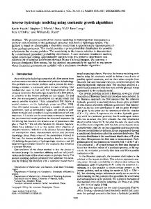
Chapter 1 – Introduction Water bodies with low algal content (Oligotrophic lakes) are pristine and healthy (Sickman, Melack, & Clow, 2003). Oligotrophic lakes still contain a healthy amount of nutrients that benefit the life within the lake. However, continued nutrient loading into a lake can destroy its pristine nature. This is a problem for any lake that is experiencing nutrient introduction at unhealthy levels. Phosphates (PO4) have become a major contributor to nutrient overloading in the state of California. We propose that P (Phosphorus) loading has increased to most Sierra Nevada lakes….The close correspondence between site-specific and regional trends suggest that large numbers of Sierra Nevada lakes may be experiencing mild eutrophication (Sickman et al., 2003). It has been suggested that atmospheric deposition (wind and rain) is the primary vehicle for phosphates to enter a water body and contribute to eutrophication (Sickman et al., 2003). Other noted sources of phosphate loading include “fast growing strains” (Schindler, Knapp, & Leavitt, 2001, p.318) of fish introduced into otherwise fishless, clear lakes as well as organophosphates from insecticides and pesticides (Selber, Wilson, & McChesney, 1993). However, the majority of the phosphates are stored in lake sediments and catchments (Sickman et al., 2003). This project will focus on sediments and catchments as the source of phosphates while considering contributing streams and hydrologic runoff as the vehicle for phosphate loading. This project implements a model of over-terrain nutrient pathways entering two separate lakes in the High Sierra. Furthermore, the project creates a geoprocessing tool that outputs a 3D model of non-point source pollution contributions and compares the two lakes based on measured amounts of total phosphorus in the water column. The 3D aspect of the model illustrates the variation between sample total phosphorus amounts at different depths within each lake while allowing a realistic view of nutrient pathways. Convict Lake and Silver Lake in the High Sierra mountains served as the study areas for this project. Convict Lake and Silver Lake are located just east of Yosemite National Park. The mountainous terrain around the lakes is very rigid with steep slopes and many streams. Both lakes were sampled for the research this project deals with, but each has a very different environmental setting. Convict Lake is secluded, relatively untouched, and used mostly by fishermen. Silver Lake has campgrounds and residential housing on its shores and is used extensively for recreation (Figure 1-1).
1
Figure 1-1: Silver Lake and Convict Lake in the High Sierras
1.1 Client The client for this project was Dr. Wendy McIntyre, Professor of Environmental Science at the University of Redlands. Her research focuses on nutrient loading in the High Sierra lakes. Water and soil samples were collected by the client and total phosphorus levels measured for June, August, and October of 2013. Dr. McIntyre hypothesizes that runoff, destruction of wetlands, fish excretion, and atmospheric deposition may be contributing to the problem. The client wanted to use a geographic information system (GIS) to trace PO4 amounts from source to lake and compare sample data at different depths within the water column of each lake. The GIS also needed to allow for future sample data integration into the analysis.
1.2 Problem Statement The client needed a way to quantify sources and visualize over-terrain pathways of nutrients as well as illustrate the difference in total phosphorus levels at different months
2
of data collection. Quantifying the contributing PO4 and linking it to total phosphorus measurements in the water column, visualizing these phenomena spatially, and allowing for future collected data to be incorporated into this analysis make GIS a valuable tool.
1.3 Proposed Solution A 3D model was judged to be the best way to visualize phosphate pathways to Convict Lake and Silver Lake. The complex patterns and terrain of the natural environment, when seen in 3D, can better highlight the dynamics of these phosphate sources and pathways. Potential pathways and sources can be targeted by including parameters such as slope, stream direction, land cover, rainfall, and soil properties into a multi-criteria analysis. These natural processes, coupled with measured total phosphorus amounts at known locations in the lake, provide the data necessary to trace these pathways from source to lake and help explain total phosphorus measurements in each lake. This solution used a custom built geoprocessing tool using ModelBuilder within ArcGIS to perform calculations and output a meaningful 3D model. The tool quantified PO4 loads that contribute through runoff into the lake directly or a stream that ultimately feeds the lake. The calculated values represent the amount of contributing PO4 from the terrain using a potential non-point pollution index (PNPI) (Munafò, Cecchi, Baiocco, and Mancini, 2005). The total contributing land upstream for the lake is included in PO4 contribution measurements. The sample data points in each lake were then interpolated to a 3D surface symbolizing variation of total phosphorus loads obtained from the analysis of each sample point. These output surfaces were created for each month of data collection and sit within the water column in the collected location on the 3D model (built with ArcScene). Separating the total phosphorus surfaces by month allows the user to toggle any month on or off for easy comparison on a 3D viewing platform. 1.3.1
Goals and Objectives
The goal of this project was to create an analysis application for scientists to visualize phosphate sources and pathways to Convict Lake and Silver Lake. Dr. McIntyre and her students can use the application to add data to the analysis and 3D model. The primary objective was to use sample data from each lake to show monthly differences in total phosphorus levels between the lakes as well as at different depths. The differences are possibly due to their lake use scenarios, and the GIS tool helps to quantify those differences by total PO4 contributing through runoff as a factor in measured amounts within each lake. While this analysis could not determine the exact cause of PO4 loading to the High Sierra Lakes, it is a useful terrain-focused unit for nutrient loading research. 1.3.2
Scope
The scope of this project was to create a tool that the client can use to compare the measured amounts of phosphates between the lakes and between different depths, and output a 3D model comparing those lake measurements to their respective contributing runoff PO4 loads within each lake’s watershed. The format of the output model was shared as an online 3D web scene by converting it to an ESRI City Engine scene. The data for this project came at no financial cost. The bulk of the study area terrain and
3
hydrology data came from the USGS National Hydrography Dataset (NHD). Digital elevation models for each watershed were clipped from a larger DEM downloaded from the USGS website (http://nationalmap.gov/viewer.html). The GIS was built for nutrient loading research and making inferences about the High Sierra lakes. However, this project focuses on Convict Lake and Silver Lake only. The reason for this decision was that each lake has a different use scenario even though they are both in the same type of terrain, making them useful for comparison analysis. Silver Lake is heavily used for recreation with campgrounds and residential homes along its shores. Convict Lake is used less by people and remains in a more secluded and almost completely undeveloped location. The complexity of mountainous hydrology networks and topography made the nutrient pathway and source tracking potentially unmanageable in its far-reaching geographic extent. Identifying all contributing sources of nutrients could have sent the project extent far beyond what is reasonable, given that soil, precipitation, and land use would have to be categorized for the entire extent. Some of the known sources come from places not connected to the basin. In order to make the runoff analysis manageable, easily understood, and meaningful, a project extent was set for each lake from its respective 12 digit Hydrologic Unit Code (HUC12) watershed boundary. This is not to say that environmental and anthropogenic entities do not contribute to the lake’s nutrient loads outside this boundary, but for the purpose of a time efficient, quantifiable GIS answer this was an adequate boundary (refer to Section 4.2). This boundary was chosen for the following reasons:
The HUC12 watershed was the smallest usable area in terms of drainage for Convict and Silver Lakes. All streams within the HUC12 watersheds exit the watershed from a single outlet. All smaller catchments within the HUC12 watersheds are completely contained within the HUC12 watershed boundary; meaning all streams within those catchments still ultimately leave the same watershed outlet. According to USGS watershed delineation criteria, all streams outside the HUC12 watershed boundary flow toward a different watershed.
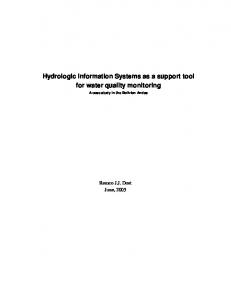
Sample data for soil and water used for this project were collected in monthly trips by the client. Convict Lake data included August and October of 2013 and prototype data created for March and May using SPSS to generate sample measurements. This created a total of four months of data for Convict Lake. Silver Lake data included June, August, and October and synthetic data created for January, March, and May using SPSS to generate sample measurements. This created a total of six months of data for Silver Lake. The bathymetry data for Convict Lake was collected in October, 2013 using a depth finder on a single day canoe trip across the lake. Silver Lake bathymetry data were digitized in ArcMap 10.2 using a paper depth contour map provided by Silver Lake Resort next to Silver Lake (Figure 1-2).
4
Figure 1-2: Silver Lake depth contour map (Source: Silver Lake Resort). The imagery used for both lakes was captured in 2012 from DigitalGlobe Foundation for Convict Lake and USGS for Silver Lake. The stream and watershed data from the NHD were delineated in 2009. This project assumed no significant change in stream location or direction, as well as no significant change in watershed location between 2009 and 2013. The temporal scope of the project are the six month and four month data analyses for Silver and Convict Lake respectively for the year 2013, using 2009 hydrology data for analysis parameters. 1.3.3
Methods
This project used a waterfall lifecycle of production because each small unit of the project had to perform correctly before the next unit could be successful resulting in a final product test as opposed to a test of each unit. The units were: prepare the data, analyze the data, construct a 3D model for each lake, and combine the analysis and model creation into a single re-usable tool (Figure 1-2). The final output 3D model can be viewed as a web scene, but that is not considered part of the requirements of the project to answer the spatial question.
5
Format Data
Analyze Data
Create 3D model Combine Analysis and Model Figure 1-3: Four Units of the Project Lifecycle
The lake samples were converted from Microsoft Excel spreadsheets to a GIS point feature class format using ArcGIS software. These datasets were cleaned to include usable attributes of phosphate measurement, month collected, depth of sample, and a unique name. The hydrology data, imagery, soil data, elevation, precipitation, and land cover type were then clipped to the boundary of each HUC12 watershed and re-projected into North American Datum 1983, UTM zone 11 north. This completed the first unit of the project lifecycle. For the next unit (analyze the data), the water sample points were interpolated into a continuous surface using their depth values (converted to elevations above sea level) and symbolized using the measured amount of total phosphorus in each sample with respect to lake volume. Using this method, a surface was created for each month of data collection for a total of six Silver Lake surfaces and four Convict Lake surfaces. The stored and retained PO4 amounts in the soil were quantified with the parameters soil permeability and land cover type. Slope, stream direction and location upstream from the lake, distance to stream, precipitation, land cover, aspect, and elevation were used to measure PO4 contributions in source to lake pathways. The entire analysis took place within the boundaries of each lake’s respective HUC12 watershed. The third and fourth unit of the lifecycle involved the 3D aspect of the project. The DEM was used to create a triangular irregular network (TIN) in ArcScene software. This TIN surface was used as a base height for all datasets and imagery within the watersheds. A 3D model was created for each lake’s watershed and each lake basin. Simply put, each lake was represented as a transparent 3D polygon in which the interpolated monthly water sample value surfaces are visible in the water column. The resulting rasters of contributing PO4 amounts from the PNPI analysis were laid over the top of the 3D watershed model to illustrate where the phosphate ground sources are located and how much PO4 they are contributing. The streams represent the transportation path of PO4
6
and the interpolated water sample surfaces represent the amount of total phosphorus that ultimately made it to the lake. Finally, the output 3D model was uploaded to ArcGIS online as a CityEngine web scene. This enables the user to toggle the terrain on and off to easily inspect the lake surfaces. The monthly phosphate surfaces can be toggled by month as well to serve as a visual aid to the difference in monthly PO4 amounts between lakes and lake depths.
1.4 Audience The audience for this GIS is Dr. McIntyre and any of her students involved in the research project. The online 3D web scene could potentially receive an audience from the client’s colleagues, environmental scientists, and policy makers who may or may not have an adequate understanding of the science behind nutrient loading. GIS knowledgeable people could use the application, as well, although it was not designed for GIS research, but as a tool to assist in environmental research regardless of the user’s level of understanding in GIS technology.
1.5 Overview of the Rest of this Report Chapter 2 will discuss issues related to nutrient loading and present the literature review. It will also discuss other GIS methods for modeling runoff and how they have evolved. Chapter 2 will also highlight some studies (some with GIS methodologies) of sources of phosphate loading other than runoff. Chapter 3 will go into detail about the exact requirements of the project and why all elements in the analysis were chosen for this project. Chapter 5 will discuss the database design. Chapters 6 and 7 will discuss how the final information product was used, the results from testing it, and further research that could be conducted by adding to the 3D abilities and analysis of the GIS.
7
Chapter 2 – Background and Literature Review The purpose of this project was to provide a geospatial tool for analyzing runoff in mountainous terrain as part of a larger research project on lake nutrient loading. This could not be fully understood without examining past runoff research methodologies. Extensive literature research was conducted to better understand the nature of nutrient loading in order to better calibrate the GIS for this project to be scientifically sound. The three areas of study in this review are explaining the nature of phosphates in the environment, analyzing the quantitative methodologies used to measure nutrients from source to water, and comparing 3D techniques used in modeling mountainous terrain.
2.1 Phosphates in the Environment Water bodies with low algal content, known as oligotrophic, are pristine and healthy (Sickman, Melack, & Clow, 2003), and still contain a healthy amount of nutrients that benefit the life within the lake. However, continued nutrient loading into a lake can destroy the pristine nature. Lakes are a valuable natural resource to California and they are important for recreation, aquatic life, and other natural processes. The High Sierra lakes are experiencing an increased amount of phosphate loading which is depleting the aquatic wildlife, harming ecosystems, and ruining the quality of the water by introducing algae. Continued phosphate loading will further degrade the lakes by introducing extreme amounts of algae through a process called eutrophication (Zhang, 2011; EPA, 2011). Eutrophication (Figure 2-1) is the process by which a water body acquires a high concentration of nutrients, especially phosphates and nitrates (Art, 1993).
Figure 2-1: Eutrophication (www.eutrophicationhumaneffect.wordpress.com).
9
Algae grow in the eutrophic water body, and when they die the decomposing organisms consume the oxygen in the water. Figure 2-2 illustrates the resulting “dead” lake, in which aquatic life cannot survive. The eutrophication process occurs naturally but at increasing rates as a result of human activity (Art, 1993; EPA, 2011). Nutrient loading has been recognized by the EPA as a potential threat to water bodies and it has taken steps to reduce loads by introducing a state level action plan for phosphate reduction (EPA, 2011).
Figure 2-2: A pristine lake compared to eutrophic (dead) lake. (lakescientist.com)
Nutrients enter a water body from a number of sources. Phosphates within the environment have been researched to determine their main sources and to measure their concentrations. It has been suggested that atmospheric deposition (wind and rain) is the primary vehicle for phosphates to enter a water body and contribute to eutrophication (Sickman et al., 2003). Atmospheric deposition is generally accepted as the leading source of nutrients to water bodies (Sickman et al., 2003; Weathers, Simkin, Lovett, & Lindberg, 2006; Berger, 2014). Many GIS models have been developed to quantify atmospheric deposition of polluting nutrients from wind (Brooks, 2012) and rain (Weathers et al., 2006). Other researchers have suggested that sources of nutrient loading include fast growing strains (Schindler, Knapp, & Leavitt, 2001, p.318) of fish introduced into otherwise fishless, clear lakes, and organophosphates from sprays of insecticides and pesticides (Selber, Wilson, & McChesney, 1993). The fish introduction source can easily be quantified with minimal need for a GIS. Another factor contributing to increase in phosphorus is the decrease in nitrogen most likely caused from lack of snowpack in dry years and the resulting lack of runoff. Climate change has been cited as the cause of 10
some of these dry seasons (Sickman et al., 2003). Elevation was found to be the major contributing terrain element above wind and vegetation type; higher elevations experienced higher levels of deposition than areas in lower elevation (Weathers et al., 2006). These pivotal research projects on phosphate loading provided useful information and could be more informative by considering terrain pathways as a significant method of analysis. The overarching problem with researching a nutrient’s path through the environment is that it is only found in trace amounts at sampling sites. The problem of tracking the paths and sources of phosphates is dramatically increased when combined with all other nutrients on the same or similar path, as there are no definite boundaries of nutrient movement. Sickman (2003) states, “The atmospheric deposition of…phosphorus represents a large fraction of the nutrient inputs to high elevation, Sierra Nevada lakes”, but that “phosphorus is not commonly measured in atmospheric deposition,” and that the majority of the phosphorus is stored in “lake sediments and catchment”. It is important to note that the GIS utilized in this study considered only sediments and catchments as a source and hydrologic runoff as the pathway of PO4 loads into water bodies.
2.2 Quantitative Methodologies Methods of tracking these nutrients have been implemented in the past. One example is the LandMod model in which landscape variables in a GIS were coupled with atmospheric deposition, elevation, and vegetation type to estimate the amount of nutrients within the Great Smoky Mountains National Park from a local monitoring station (Weathers, Simkin, Lovett, & Lindberg, 2006). This model was as an empirical model meant to classify land types by the amount of deposited nutrients measured in an area, and used independent variables such as canopy cover and elevation to delineate the classifications. GIS was used to classify the land types within the park to map deposition. There are limits to research methods for atmospheric deposition because of the data limitation “beyond the immediate vicinity of dry-deposition [wind] monitoring stations” (Weathers et al., 2006, p.1591). The data for this project only had one atmospheric monitoring station for each lake, making inferences about wind deposition for the entire watershed difficult to quantify. This project focused on the hydrologic runoff component of nutrient loading by mathematically quantifying PO4 loads based on many easily attainable environmental parameters. 2.2.1
Runoff Models
GIS has been most successful in PO4 flow analyses that do not consider atmospheric deposition. Sorano, Hubler, Carpenter, and Lathrop (1996) developed a model in which a potential phosphate path was mapped along surface overland flow. Their method was to assign values to a raster based on distance from the riparian flow path, distance to a water source, known phosphorus amounts, and finally the potential amount of PO4 that could be off-loaded across the terrain along its path to the water body. In other words, while further travel of sediment meant less PO4 to contribute to the pollution, all ground units were considered potential sources if they met the criteria of falling within the possible overland flow path (Soranno, Hubler, Carpenter, & Lathrop, 1996). 11
The key to quantifying nutrients coming from over-terrain flow is identifying supply, fate, and transport of these nutrients from headwaters to receiving waters within a watershed (Brakebill, Wolock, & Terziotti, 2011). Spatially referenced regressions on watershed attributes (SPARROW) is one of the most intense models for measuring contaminant flux, sources, and transport. It uses a GIS approach based on a digital hydrologic network to quantify the contributing nutrients. Brakebill (2011) wrote, “A digital hydrologic network of connected surface-water pathways and the areas they drain can be used as a foundation for a consistent spatial framework to characterize and analyze watershed processes” (p. 917). This watershed-focused approach proved to be the most useful for this project. It utilized spatial and temporal data of measured PO4 amounts in the lakes being studied, enabling a comparison to estimated PO4 amounts within different land cover types along the same hydrologic network. The watershed and its contained streams coupled with field measurements give a GIS the ability to quantify and visualize relationships both spatially and temporally (Brakebill et al., 2011). The SPARROW model is ideal for watershed analysis of nutrient runoff because it takes into account watershed boundaries, catchment boundaries, stream network, and land cover types (used to determine PO4 contribution rates and nutrient storage amounts). However, it was limited for this project because it is typically used in much larger basins and requires flux monitoring stations along the stream network for a relatively long period of time (Robertson & Saad, 2011). The parameters needed for the SPARROW model would be difficult to attain in this project because the two watersheds were smaller than those used in SPARROW analysis, and field data were collected only for Silver Lake and Convict Lake, as opposed to the entire watershed stream network. In order to keep the pollution contribution output of a robust model such as SPARROW while maintaining this projects timeframe and data availability, a simpler model was needed for success. 2.2.2 Multi-Criteria Analysis (MCA) Multi-criteria analysis uses the same concept as the SPARROW model, but is not confined to complex formulas, large study areas, or the need for extensive locally collected data. It is a low-effort approach in that the data needed for the runoff model are easily produced from readily available GIS data (Zhang & Huang, 2011). MCA has been used in many fields where timely outputs were needed, such as nature conservation in heavy agricultural regions and flood risk assessment studies. This model is based on a criterion or judgment of different environmental parameters (Zhang et al., 2011). Accumulating these criteria into a single output is the decision making process – in the case of this project, an estimate of PO4 – behind MCA. Four criteria were chosen for this project using the MCA design developed by Zhang & Huang (2011) for nitrogen or phosphorus runoff: phosphorus export rate per unit area; flow path distance to water body; efficiency of runoff generation; and precipitation as the climatic driving force. These are given the names E, F, H, and P index, respectively (Zhang et al., 2011). The next step, illustrated in Figure 2-3, was to take these criteria and put them into a decision matrix for comparison across attributes, which entailed performing a calculation with all four indices as input to derive a final output of nutrient contribution for the entire surface of the watershed.
12
Figure 2-3: MCA analysis for nutrient runoff with PNPI as pollution contribution (adapted from Zhang and Huang, 2011). Zhang & Huang (2011) utilized the technique ordered preference by similarity to ideal solution (TOPSIS) as the final calculation. However, TOPSIS allows the formula, not the experts, to determine the analytical hierarchy (weights) of the indices E, F, H, and P. This project designed a GIS tool meant for the user to input the weights they desire for each index based on expert advice and collaboration. To facilitate the freedom of deciding the importance of each environmental factor involved in PO4 runoff, a much simpler calculation known as potential non-point pollution index (PNPI) was used as the final calculation of PO4 contribution for this project (Figure 2-4). 𝑷𝑵𝑷𝑰 =
((𝑬 𝒘𝒆𝒊𝒈𝒉𝒕)(𝑬) + (𝑷𝒘𝒆𝒊𝒈𝒉𝒕)(𝑷) − (𝑭𝒘𝒆𝒊𝒈𝒉𝒕)(𝑭) − (𝑯𝒘𝒆𝒊𝒈𝒉𝒕)(𝑯)) − 𝑷𝑵𝑷𝑰(𝑴𝒊𝒏) 𝑷𝑵𝑷𝑰(𝑴𝒂𝒙) − 𝑷𝑵𝑷𝑰(𝑴𝒊𝒏)
Figure 2-4: Potential Non-Point Source Pollution Index equation.
13
The PNPI here has been adjusted from Munafò et al. (2005) to include parameters from nutrient runoff MCA (Zhang & Huang, 2011) and has been standardized with values 0 – 1 for each pixel in the final output raster. A value of 0 indicates minimum contributing PO4 runoff and a value of 1 indicates maximum contributing runoff. PNPI was designed to allow the GIS to represent the physical reality of the watershed with few input data. Its validity as a nutrient runoff method is reinforced in that its workflow is very similar to the environmental impact assessment used by the EPA (Munafo et al., 2005). Fewer input data, in the case of watershed runoff analysis, allow the problem to be addressed without complicating the evaluation process (Zhang & Huang, 2011). This simplified model is possible because of the high quality of hydrologic GIS data available for no cost. Luzio and Arnold (2004) emphasized the growing availability of hydrological datasets and terrain models that can be called upon in a GIS to better model pollution sources and the path they take to undesired locations such as lakes. One of the most useful datasets for this project was the National Hydrography Dataset (NHD). It is GIS format data updated from the RF1 hydrographic database built in the 1970s that represented the spatial reality of water and provided the necessary stream, watershed, sink, and catchment data necessary to estimate various environmental conditions that involved hydrology (Brakebill et al., 2011; Simley, 2005). The more recent version NHDPlus provided even greater detail by adding catchment boundaries smaller than HUC12 watershed boundaries, as well as quantity amounts of accumulated flow. The consistently updated USGS NHDPlus makes the previously described runoff models easier to implement for large scale, lake level studies such as this one. Figure 2-5 illustrates the increase in hydrologic detail from the original RF1 to today’s NHDPlus.
14
Figure 2-5: The difference in detail of RF1 (a) and NHDPlus (b) hydrology data (Brakebill, 2011).
This project utilized the NHDPlus dataset, along with ArcGIS Spatial Analyst and Network Analyst, to quantify PO4 loads that are heavily reliant on hydrology for transport. This type of parameter-enabled system, coupled with visual path outputs and 3D modeling techniques, is the next step in the application of GIS in pollution source and path studies.
2.2.3
3D Modeling Techniques
This project used the ArcScene suite of ArcGIS for Desktop to construct 3D models of the HUC12 watershed for Silver Lake and Convict Lake. Three dimensional lake basins for the lake water columns were constructed, as well. Newer software such as Arc CityEngine were available but were not as feasible for this project. CityEngine is designed for urban planning and outputting models of buildings and infrastructure, as opposed to a natural area (www.esri.com/software/cityengine). ArcScene was more efficient for this project because of the need for a quick and convenient 3D model to display analysis output data without having to spend excessive amounts of computer resources and processing time when rendering the final model (Li & Zheng, 2012).
15
The base component of this GIS was the 3D terrain in which all data and analysis results were overlain. The software had three different methods of creating terrain, or digital elevation models (DEM): grid, triangulated irregular network (TIN), or the terrain dataset based on z values of input data (Li & Zheng, 2012). The TIN and terrain datasets required some medium of elevation data to be created. The grid is a continuous surface of elevation data and was available for this project in raster format. The raster was interpolated to a TIN using the 3D analyst extension of ArcGIS for desktop to create point vertex locations at the center of each pixel and draw a terrain with edges connecting the elevation points. The TIN was used for the watershed models because of its ability to handle the vector data associated with this project. One of the necessary functions of this project’s 3D models was that it cut out the exact spatial area of each lake (vector polygons), enabling the 3D lake basin to stand alone as a model feature. The lake and the watershed were accurately located geographically, but were separate entities in the model. The user can view and navigate the lake without having to move the entire watershed. The area of the lake was easily excluded from the vector based TIN model where excluding pixels from a grid would distort the lake boundary to meet the spatial resolution of the raster (Figure 2-6).
Figure 2-6: Silver Lake over a base raster elevation grid (A) and a TIN (B).
Water bodies and imagery for this project were rendered in 3D with more accuracy and photorealistic visualization when using the vector based TIN model as opposed to the pixel based grid model because of the common loss of terrain accuracy and x,y location of surface details when using the grid for terrain modeling or 3D GIS analysis (Năpăruş, Golay, Stupariu, & Patru-Stupariu, 2013; Li & Zheng, 2012). For example, if a 10x10 16
meter pixel represents a constant elevation across the area of the pixel, this can be problematic if a stream is flowing down the side of a mountain at x meters per 10 meter pixel. The TIN can be adjusted to compensate for that error by adjusting the 3D Analyst parameters. The TIN, although more memory intensive, is better suited for small areas and surfaces that are complex such as mountainous regions (Esri, 2012). The TIN can be adjusted to best fit a project by finding a compromise of spatial accuracy and cost in computing time/data acquisition (Esri, 2012). These adjustments can be made in the 3D Analyst extension of ArcGIS by changing parameters, including z tolerance, node quantities, and contributing features. The z tolerance refers to the maximum allowable difference in the grid elevation value of a pixel and the elevation value of a TIN node. Figure 2-7 illustrates the resulting accuracy differences when increasing the amount of TIN nodes and decreasing the maximum allowable difference in grid and TIN elevations.
Figure 2-7: TIN with z tolerance of 178m (A), 140m z tolerance (B), 100m z tolerance (C), and 50m z tolerance (D) (ArcScene10.2). Table 1 lists the tested z tolerance values and the resulting node quantities used. Table 1.
Z tolerance and Node Quantities for Rush Creek Watershed. Z Tolerance
178m 140m 100m 50m
Nodes 8060 8224 8525 9935
17
The elevation grid for this project considers all 10x10 meter ground units as one constant elevation, which is not realistic. Figure 2-8 explains how the raster error is compensated by the TIN using a maximum of 20 million nodes to achieve a z tolerance of 50 meters.
Figure 2-8: Difference in a TIN surface and its input raster. Notice that a smaller z tolerance will result in a more gradual increase and decrease by using more nodes for the surface (www.esri.com).
Since this project updates data only on a monthly basis, is heavily involved in vector format terrain properties, and stores a finished model online, computing time was less important than spatial accuracy. The TIN for each watershed was created with a 50 meter z tolerance and 20 million node maximum. This does not mean that 20 million point locations exist in each model. The advantage of the TIN for the small watersheds in this project was that it can use up to 20 million nodes to achieve 50 meter or less z tolerance. Silver Lake watershed only used 9,935 nodes to meet the 50 meter tolerance; allowing for relatively fast rendering time and a high quality DEM to support the 3D imagery (Figure 2-9).
18
Figure 2-9: Raster to TIN surface with Digital Globe 1 meter imagery.
2.3 Summary The literature provided many examples of research that have concluded that phosphates have a negative effect on water bodies at high rates of exposure. Many models have been developed to quantify and trace nutrients from a variety of sources. Runoff models range from statistically robust, data intensive algorithms, such as SPARROW, to simple nutrient contribution measurements such as multi-criteria analysis. Three dimensional modeling coupled with GIS analysis of nutrient runoff is a feasible way to perform complex analyses and still have the advantage of easily understood results provided by a realistic 3D model. This project focused on MCA as a runoff model, PNPI for phosphate contributions, and 3D modeling to explain the relationship between lake phosphates and hydrologic runoff as a source at the watershed level.
19
Chapter 3 – Systems Analysis and Design 3.1 Problem Statement The client needed a way to quantify sources and visualize over-terrain pathways of nutrients, as well illustrate the difference in total phosphorus levels at different months of data collection. Quantifying the contributing PO4 runoff and linking it to total phosphorus measurements in the water column, visualizing this phenomena spatially, and allowing for future collected data to be incorporated into this analysis make GIS a valuable tool.
3.2 Requirements Analysis The functional requirements for this project were 1) quantify the amount of PO4 contributing to lake pollution through hydrologic runoff; 2) illustrate the monthly differences in mg/L of total phosphorus within each lake’s water column; 3) illustrate the analysis results on a 3D model formatted for an interactive online web scene. Non-functional requirements mostly related to building the four indices used to calculate the PNPI, as well as the bathymetry data needed to construct 3D lake basins. Downloaded datasets varied in file format and had to be processed into usable grids in order to create rasters for PO4 export rate (E index), distance to stream (F index), nutrient retention (H index), and annual orographic precipitation (P index). Spatial Analyst extensions within ArcGIS desktop 10.2 were used to find stream distances. Network Analyst was used to find contributing catchments upstream from each lake inlet because downstream catchments were excluded as they do not contribute to the lake pollution even though they reside in the same watershed. Arc GIS 3D Analyst was used to interpolate continuous surfaces for both Silver Lake and Convict Lake at a monthly temporal scale, as well as construct and edit TIN surfaces for each lake’s watershed. ArcGIS 10.2.1 or higher is required because of the necessity of the ArcScene to 3D Web Scene tool available only in new versions of ArcGIS. Finally, an ArcGIS Online account was used to load the final scenes to City Engine Web Viewer for interactive display. The client provided the necessary sample data in Excel format to analyze total phosphorus loads of each lake. Users are provided an Excel document to record field data measurements to prevent data entry mistakes and must provide weights for each of the four indices (E, F, H, and P) before running the tool. The tool delivered in this project automated the entire process, as well as provided the four indices needed to perform analysis. Multi-criteria analysis (MCA), (Zhang & Huang, 2011) and Potential Non-Point Source Pollution Index (PNPI), (Munafo et al., 2005) were the runoff models the tool used to output a meaningful solution. Three dimensional visualization was enhanced and made interactive by uploading the tool’s resulting 3D web scene file (.3ws) to ArcGIS Online. The resulting web scene, viewable in a City Engine Web Viewer, was a separate element from this project’s deliverable, but is the best available way to interact with analysis results on a close-to-reality platform. The properties of the ArcScene document are maintained in the online version of the 3D model. These properties include layer symbology, bookmarks, area of interest (AOI),
21
and data credentials. There are two final 3D web scenes: one for Convict Creek Watershed and one for Rush Creek Watershed. Table 2 lists the functional and nonfunctional requirements of the GIS. Table 2.
Project Functional and Non-Functional Requirements Functional Requirements
Non-Functional Requirements
Must create continuous surface of P load measurements for each month of data collection Must create continuous surface of PNPI for entire watershed upstream from each lake
User must input weights for each parameter
Must create point feature class of sample data and add elevation values Must handle 3D rendering, symbology, metadata, and conversion to web scene file format
User must record data in Microsoft Excel 2013 template provided and use as input table ArcGIS 10.2.1 or greater with Spatial Analyst, Network Analyst, and 3D Analyst extension ArcGIS Online account for 3D web scene
3.3 System Design Formatting the data for this project required treating the lakes and the watersheds as separate entities within the GIS. Rush Creek Watershed and Convict Creek Watershed would be two separate 3D models. Water sample analysis at the lake level and non-point source nutrient pollution analysis at the watershed level required that each watershed’s model have a separate lake and watershed component. The difference in the two analyses is that water samples contain a known measurement while watershed environmental data made an estimate of the amount of PO4 being contributed as a result of hydrologic runoff. Figure 3-1 shows the system design incorporating both watersheds.
22
Figure 3-1: System Design Figure 3-2 illustrates the system workflow used to manually format the data as well as the system workflow that automatically analyzes and combines that data with 3D modeling.
23
Figure 3-2: System Workflow
3.4 Project Plan The original plan for this project was changed after identifying spatial analytical needs, technological barriers, and scope within the project time frame. The original plan was to compare Silver Lake to Convict Lake for each month of data collection. The idea was to compare one lake with residential land use along its shores to the other, which had very little non-native land cover. However, this lake comparison was accomplished by statistical analysis of total phosphorus measurements in the lakes and had minimal need for spatial analysis. Erin Berger (2014), head of research and data collector at the time of this project, discussed the difference in total phosphorus loads between Silver Lake and Convict Lake and clearly identified the results in her paper on the same project. While knowing the difference between each lake’s seasonal total phosphorus loads was pivotal in understanding the increase in High Sierra lake nutrient loading, there was no clear need for GIS in answering the question, “What is the difference in total phosphorus loads between Convict Lake and Silver Lake?” The question that posed a need for a GIS was, “Where are these total phosphorus loads coming from?” That is why a nutrient runoff model was decided as the most useful approach in which GIS can help further understand nutrient loading in the High Sierras. This project’s GIS still enables the user to visually compare monthly total phosphorus loads of each lake, but also provides an idea of how
24
much of those nutrients are coming from hydrologic runoff, a phenomena in which GIS has become an increasingly valuable tool. This shift in direction for the project resulted in schedule and resource changes. The focus on hydrologic runoff required GIS software which was different from the lake comparison plan in which online mapping and analysis were to be used. The schedule was adjusted for six months of training and geoprocessing tool construction after discovering that the online tools could not facilitate the needed analysis and 3D modeling. The next major change came in the technological approach to the project. The overarching theme was that the client’s GIS knowledge was limited and the proposed system was to allow her, as an environmental scientist, to use the tool without having to learn more about GIS. Furthermore, her students, heavily involved in data collection and research, should be able to use the system in the future. Since the water sample results were stored in an Excel file, a format which the client was already familiar with, it seemed logical to leave it that way. In the beginning, Esri Maps for Office seemed the ideal solution. It is an add-on for Microsoft Office with which the user can generate maps in the document based on column data, and requires no desktop GIS software to function. However, this Office-based tool was limited to simple hot spot analysis (no self-constructed algorithmic modeling) and was not capable of the 3D modeling which the project required. The original plan and system tools can be seen in Figure 3-3 with blue lines representing the system workflow and yellow lines representing the analysis taking place on a server.
25
Figure 3-3: Original system design with limited use for this project It was then decided that a geoprocessing tool in ArcGIS for desktop was the appropriate information product because of its ability to accept an Excel file as input, perform algorithmic analysis (MCA and PNPI), and generate a 3D model while still requiring minimal GIS software knowledge from the user (Figure 3-2). The disadvantage of choosing this desktop solution is that the client was required to acquire ArcGIS software and store any data collected in the future in a provided Excel file that was preformatted to prevent user input error. The advantages were that the tool can be used for data collected in the future, can be updated when newer precipitation, land cover, and elevation data become available, and has a very intuitive interface for any user. The final change to the original project plan was the scope of the analysis. The client not only collected water samples but shoreline soil samples, as well. The watershed analysis chosen for this project created a unit-less index of PO4 contribution. Incorporating the soil data, with a unit of parts per million, would involve a much stricter runoff model than the MCA used for this project. Another need to reduce scope was because all properties of the output PNPI were to be transferred to an online web scene. This is possible to do but would involve multiple programming languages in which the required training and code writing put the project at risk of not being completed. The WNAT performs analysis and outputs a 3D model ready for online web viewing, but the
26
user must upload the scene to ArcGIS online City Engine Web Viewer without depending on the desktop tool to perform this task. Figure 3-4 shows the original project plan and the revised project plan as actually transpired as of the end of June, 2014.
27
Figure 3-4: The original project plan (A) and the revised project plan (B)
28
The most significant deviation from the original project plan was in building WNAT. The idea was to have a simple comparison of the two lakes take place in the Excel document where the data were stored. This approach was drastically changed when the spatial solution went from a lake comparison question to a quantifying watershed PO4 runoff question. It was discovered that Esri Maps for Office was not sufficient for handling watershed analysis or 3D rendering and a geoprocessing tool was needed. Building the analysis tool required six months, a significant change from the original lake comparison model which would have taken approximately three months. This increase in time was a result of many trials of the PNPI analysis, hard coding symbology and 3D construction within the workflow of the tool, and modifying the tool to accept parameter weights in a Python script. The next notable change to the original plan was excluding the soil data from the final analysis. First, parameters used in the MCA and PNPI in this project did not require the soil data. Second, soil PO4 concentrations were measured in parts per million while the water samples are measured in mg/L, making it difficult to include both soil and water on a common interpolation scale. Incorporating the locally collected soil data would have created a more robust analysis, but would only have put the project completion schedule at risk as well as complicate the understanding of the MCA with its four watershed spanning environmental parameters.
3.5 Summary The functional requirements for this project were 1) quantify the amount of PO4 contributing to lake pollution through hydrologic runoff; 2) illustrate the monthly differences in mg/L of total phosphorus within each lake’s water column; and 3) illustrate the analysis results on a 3D model formatted for an interactive online web scene. These requirements were met with a geoprocessing tool called Watershed Nutrient Analysis Tool (WNAT) which was the chosen deliverable for this project. The original project plan was to compare monthly total phosphorus loads in Silver Lake and Convict Lake, but was later changed to quantify the amount of PO4 loads coming from each lake’s watershed. This change was in response to the spatial question of where the nutrients are coming from as opposed to how different they are in two separate lakes. The original system design was to utilize Esri Maps for Office to generate maps of nutrient data analysis in the Excel file where the data was originally stored. This plan was replaced with a desktop GIS application because of the limitations on algorithmic analysis and 3D functionality in Maps for Office. The tool and output 3D model of this system met all functional requirements. The GIS for this project is a useful information product for understanding nutrient runoff in the High Sierra.
29
Chapter 4 – Database Design 4.1 Conceptual Data Model Phosphorus is transported to a mountainous water body by different driving forces. WNAT estimated the amount of PO4 entering Silver Lake and Convict Lake, considering hydrologic runoff as the driving force. Nutrient export rate, precipitation, nutrient retention, and distance to stream were considered in calculating the PNPI for each watershed. Nutrient export rates and precipitation are the two parameters that strengthen nutrient contributions. Increase in distance to stream and nutrient retention are the weakening factors in nutrient contributions. MCA determines the importance for each of these parameters and accounts for the loss or gain in nutrient contribution, as illustrated by the PNPI. Water samples from each lake were used to estimate the amount of total phosphorus for a comparison between lakes and between different months. This approach allowed a comparison between the watersheds using the PNPI to account for varying amounts of non-point pollution running off the mountainous terrain. Each lake’s total phosphorus amounts were viewed by separate months to highlight months of low or high nutrient introduction. The PNPI and the monthly lake total phosphorus measurements were communicated on a 3D surface where the contributing PO4 spans the mountainous terrains showing rise and fall in elevation, land cover types, and stream locations, while the lake total phosphorus amounts descend into the lake basin to highlight the close-to-reality dimensions of watershed and lake. Figure 4-1 shows the conceptual model in which locally collected total phosphorus measurements were coupled with environmental parameters at the watershed level to quantify and communicate PO4 load transport on a 3D surface.
31
Figure 4-1: Conceptual Data Model
4.2
Logical Data Model
The lake sample data for this project had to be first formatted for a GIS and then processed in WNAT to illustrate monthly differences in total phosphorus concentrations. This involved cleaning the data files and formatting them to be used as input for interpolation and monthly splitting. Data were available for each watershed to be used in 3D modeling and runoff analysis, but bathymetry data had to be collected and processed in order to create 3D basins for Silver Lake and Convict Lake. The client’s data, the watershed environmental data, and the bathymetry data all converged to create a meaningful solution. Figure 4-2 illustrates the interaction between these three data classes and how it was decided to use them within the system.
32
Figure 4-2: Logical Model – 3D data, lake data, and watershed data all converge.
The lake total phosphorus load analysis and the nutrient runoff analysis were performed using two very different types of data. One had known measurements at point locations within the lake basin (mg/L) while the other uses varying units of measurement from environmental parameters to create an index (0-1 values). Table 3 shows the varying units that were used in calculating one PNPI raster and lake PO4 contribution surface.
33
Table 3.
Units of Measurement for all WNAT input data
In order to communicate watershed analysis in conjunction with lake data analysis, the model treated them as two separate entities in the system. The result was a logical model that worked for both watersheds of interest while treating watershed and lake as two separate analyses. Figure 4-3 illustrates the inevitable separation of the two watersheds in space and the purposeful separation of the land and lake for both Rush Creek Watershed and Convict Creek Watershed.
Figure 4-3: Rush Creek Watershed and Convict Creek Watershed / detached lakes.
4.2.1 Lake Sample Data The client’s data consisted of two measurements for each sample location. The average of the two was used in the total phosphorus load interpolation. The names were arbitrary 34
and depth was only a factor in, at most, three samples in a month. Three months of data for Silver Lake and two months for Convict Lake were available at the time WNAT was being constructed. Given that WNAT is meant to be used for data collected after completion of this project, synthetic data were used in analysis to allow a more varied dataset in a larger temporal scale. The original data, coupled with the synthetic data, consisted of six months of data for Silver Lake and four months of data for Convict Lake. The lake sample data were cleaned from their original Excel file to include a single record for each sample point, which included the location, month, total phosphorus measurement (as average of two original), and depth. The location was used to determine an X,Y along the lake surface and depth was used to determine each point’s Z value based on its subtraction from the lake surface elevation above sea level. The month of each set of points was used to separate the data into their own monthly datasets. These datasets were interpolated for the entire lake basin based on the mg/l of total phosphorus at each point. Table 4 and 5 show the source data and the system formatted version used to interpolate total phosphorus loads for each lake.
35
Table 4.
Source Data
36
Table 5.
System Formatted Data
The system formatted version of the Excel file was also the template delivered with the GIS at the end of the project. Storing future data in this file prevents user error and honors the table structure required for WNAT. 4.2.2
Environmental Parameters
The environmental parameters were built using data obtained in varying formats. The key dataset for building the four indices used in MCA was land cover. Land cover was integrated in creating the E index (nutrient export rate) and the H index (nutrient retention). It was also the limiting dataset, at 30 meter resolution, serving as a variable in calculation of PNPI alongside a ten meter DEM, a ten meter precipitation dataset, and a one meter imagery dataset. This was acceptable as a PNPI resolution given that Rush Creek watershed has an area of 151 square kilometers and Convict Creek watershed has 155 square kilometers. Thirty meter resolution became an issue when observing the
37
model at lake level scale, but was not existent across the lake basins. The basins maintained a one meter resolution for the total phosphorus load surface raster because of the watershed and lake being two separate entities in the model. The E index determined nutrient export rates in kg/ hectare/year. Those export rates were assigned to each land unit (30 square meters) based on that unit’s land cover type after being converted to unit kg/30m2. The conversion was accomplished by assigning the hectare values to the land cover type using the ArcGIS reclassify tool and then converting it to thirty meter values using the raster calculator tool. The same land cover dataset was used in deriving the H index but was not the only deciding factor in nutrient retention. Using the land cover dataset twice did not create exaggerated results because it was coupled with the soil hydrologic unit data to be used in the H index retention equation (Figure 4-4) which estimates nutrient retention for each land unit.
Figure 4-4: Nutrient Retention Equation used to calculate H index
CN is the curve number for runoff potential given by the Soil Conservation Service (SCS) based on soil permeability and land cover. A separate raster was created for soil permeability and used with a raster of land cover to create a raster of CN values. The CN raster was input into the retention equation to get s, the nutrient retention value, for each pixel creating the H index. F index was calculated using ArcGIS path distance tool, but with flow direction also playing a role in determining distance to a stream. The further from a stream the land unit resides the more nutrient percolation occurs along its path. A line feature class representing all streams in the watershed was used as the target for all nutrients whose contribution loads increase as distance to stream decreases. Thus, locations next to a stream are given a higher contribution value than locations farther away. The P index was created using the DEM, as well as yearly precipitation data. Precipitation data came as polygons representing precipitation contours with unit inches per year. This was converted to a ten meter raster dataset and used with the DEM to calculate the P index. In order to facilitate the possible orographic effect that mountainous terrain can have on rainfall patterns, increased elevation was treated as increase in rainfall if the slope was perpendicular to the direction of the wind and on the windward side. Therefore, the P index was a result of rainfall in inches per year along a constant contour boundary, but changed within that boundary by adding precipitation amounts for wind facing, higher elevations and standardizing the results with values zero to one. Other environmental factors in the watershed analysis were sub-watershed catchments, stream network, and Rush Creek housing footprints. Catchments were clipped from the NHD Plus dataset to include only catchments within each watershed, and upstream from each lake of interest. The resulting upstream catchments were used as a mask for the final PNPI raster surface. The stream network was added to the 3D model
38
to illustrate the known drainage channels that transport PO4 loads to each lake. Residential land use is present only in the Rush Creek Watershed and therefore its model had footprints to illustrate the presumed effect that human activity may influence nutrient loads in Silver Lake. Figure 4-5 illustrates the finished model with and without the PNPI and imagery. Notice that the PNPI surface is excluded downstream from the lake and the contour lines are visible in the absence of the PNPI surface and imagery to enhance the total phosphorus load raster in the basin.
Figure 4-5: Watershed with imagery and PNPI (A), without imagery and PNPI (B), and lake level view without imagery or PNPI (C). 4.2.3
Bathymetry Data
Bathymetry data for Silver Lake and Convict Lake were obtained from two separate sources and were the most difficult to collect. Convict Lake bathymetry data were collected by the author using a depth finder and GPS along the lake surface. Silver Lake bathymetry was derived from a paper depth map available from a Silver Lake Resort on site. The GPS data were input into ArcGIS as a point feature class using Department of Natural Resources Garmin GPS software. The paper map was digitized using reference 39
points of the highway along the lake shore, the inlet and outlet of the lake, and the identifiable grass bed that resides on the east side of the lake. The georeferenced image was then used to digitize a contour line feature class with attributes for depth. Depth points for Silver Lake and contour lines for Convict Lake were both used to create a TIN surface, or basin. The TIN values had to be exaggerated to better illustrate lake depth due to the true depth being visually insignificant compared to the highly varying topography change around the lake. Every total phosphorus load raster generated used the TIN surface built for each lake as its base height. Figure 4-6 shows the bathymetry source data and the resulting basins.
Figure 4-6: Bathymetry sources and resulting 3D lake basins in TIN format
4.3 Data Sources The data from this project had a temporal range of 12 years: 2001 – 2013. The NHD data were a derivative of the updated RF1 which has data collected from the early 1900s, but has been consistently updated since that time. It is used by USGS and is the most useful and largest hydrologic dataset for all of the United States. Most of these datasets required data processing for use in WNAT. Sources and formats can be found in the master data list (Table 6).
40
Table 6.
Master Data List
4.4 Data Collection Methods The data that separated this project from other watershed nutrient analysis projects were the water sample data from each lake. These samples were collected by the client on a monthly basis; most studies use data from collection points that may or may not be in the water body of interest. The dataset was extended to include synthetic data in order to see the full potential of WNAT. Table 7 and 8 show the entire temporal range and data point quantity for each month of data collection at each lake.
41
Table 7.
Silver Lake temporal range and quantity
Table 8.
Convict Lake temporal range and quantity
The client and assistant floated the expanse of Silver Lake and Convict Lake in a canoe collecting water samples in a bottle. The samples were brought back to the University of Redlands and analyzed to determine the amount of phosphate in each sample. Each measurement was recorded in an Excel file, along with latitude and longitude coordinate locations. The Excel file was cleaned, georeferenced, and included in the GIS database for use in WNAT. 4.4.1 Elevation Data The elevation data used in this project were obtained from two sources. The DEM for Rush Creek Watershed was downloaded from USDA website using a map viewer to select an area of interest. The ten meter DEM raster downloaded from the website was clipped to fit the Rush Creek Watershed boundary. This dataset was based on data collected between 2000 and 2013 and was used for all analysis involving elevation, flow direction, and aspect in this project. The ten meter DEM for Convict Creek Watershed was downloaded from the USGS website (http://nationalmap.gov/viewer.html) National Map Viewer and Download Platform and clipped to the boundary of the Convict Creek Watershed. This dataset was used for all analysis involving elevation, flow direction, and aspect in the watershed. 4.4.2 Hydrography Data The hydrography data were the second most important dataset in setting a groundwork for hydrologic runoff modeling. The NHD Plus dataset provided stream lines, watershed boundaries, sub-watershed catchments, lake boundaries, as well as the attributes
42
necessary to use the network analyst extension of ArcGIS to determine the streams contributing to the lake of interest. Watershed boundaries are vital for hydrologic runoff models because they adhere to the physics of water movement and are not biased to perceived boundaries. Fortunately, the NHD Plus was available for most of the United States during the time this project was implemented. It is improved in that it provides sub-watershed catchment boundaries, flow accumulation, and flow direction data. The NHD Plus was downloaded from Horizon Systems Corporation website (http://www.horizon-systems.com/nhdplus/NHDPlusV2_data.php), a third party download site for obtaining the newest version of the NHD compiled by the USGS. The hydrology data derived from this download were clipped to Rush Creek and Convict Creek watersheds for use in this project. 4.4.3
Bathymetry Data
Bathymetry data for this project were collected from two sources. Silver Lake bathymetry was georeferenced from a paper map. The map was scanned, imported into Arc Map, and georeferenced using the most obvious features as reference points. The image was then used to physically trace depth contours as a line feature class. Convict Creek bathymetry was collected by the author. A buoyant depth finder was attached to a fishing line and cast into the water from a canoe along two transect paths, and transmitted depth measurements to a wrist watch receiver showing the depth of the lake at that point. The depth measurement was immediately recorded along with a spatial location in a GPS. The GPS coordinates and depth measurements were then extracted from the device and imported into the GIS as a feature class. The bathymetry of Convict Lake was created using these collected depth points. Both lakes’ bathymetries are represented as TIN surfaces and used as base heights for total phosphorus load surfaces generated by WNAT. 4.4.4
Land Cover Data
The land cover dataset used in this project was downloaded from the USGS Gap Analysis Program (http://gapanalysis.usgs.gov/gaplandcover/data/download). The website’s Land Cover Viewer was used to select the area covering both Rush Creek Watershed and Convict Creek Watershed. A 30 meter thematic raster was downloaded for the AOI representing land cover types. This raster was clipped to the boundary of each watershed for this project. This dataset was most useful in separating three types of land cover present in the AOI for this project: paved areas such as roads and camping lots, shrub and forested areas that span the mountainous terrain, and rocky areas that make up some of the steep mountainsides in both watersheds. 4.4.5
Precipitation Data
The precipitation data for this project were obtained from the United States Department of Agriculture (USDA). The USDA webpage for the National Geospatial Center for Excellence had precipitation GIS data available for download (http://www.nrcs.usda.gov/wps/portal/nrcs/main/national/ngce). The data were in vector format, being converted from previous years of data collection. The data were a compilation of the average of 30 years of annual precipitation data. The vector polygons
43
have the same spatial distribution as a contour line. These precipitation contours were converted to raster format and used in this project as part of the MCA analysis. 4.4.6 Soil Data The soil data used in determining the soil hydrologic unit were derived from the ArcGIS extension Soil Data Viewer (USDA). Soil reports were loaded into a Microsoft Access database where Data Viewer could extract the soil hydrologic data for both watersheds and convert them to vector format. These vector polygons were the SSURGO polygons representing different classes of soil as defined by the USDA. The derived soil hydrology data were used to determine permeability and drainage level. These classifications ranged from poorly drained to highly drained. Soil permeability classification within each watershed, along with land cover type, were used to determine values for the nutrient retention parameter (H index) in this project. 4.4.7 Imagery The imagery for this project came from two different sources. The imagery for Rush Creek Watershed came from the USGS as a download from the website (http://earthexplorer.usgs.gov). It is one meter resolution, four band, with a 2012 collection date. The imagery had to be compiled into a mosaic from eight different image tiles. The mosaic was then clipped to the boundary of the Rush Creek Watershed for use in this project. The imagery for Convict Creek Watershed came from Digital Globe as an FTP download. This imagery was free. It is two meter, eight band, with a 2013 collection date. The imagery had to be compiled into a mosaic from eight different images. The mosaic was then clipped to the boundary of the Convict Creek Watershed for use in this project.
4.5 Summary The conceptual model of this project was to quantify total phosphorus loads in the lake of interest while illustrating their transport on a 3D model. The logical model utilized a tool in which environmental parameters, locally collected water samples, and topography data could be combined to form an interactive 3D model of nutrient runoff. The data for this project came from a variety of sources and were formatted for use in this project. The environmental data were consolidated into the E, F, H, and P indices for use in WNAT. The final model treated the watershed and the lake basin as two separate entities in the GIS. This enabled the user to analyze the PNPI for each watershed and the P load measurements for each month of data collection separately. The index of 0-1 facilitated a simplified perspective of a contribution measurement that is unit-less. Nutrient export, nutrient retention, precipitation, and nutrient travel distance were used to create a logical model in which locally collected data and 3D modeling enhanced the understanding of phosphate loading in the High Sierra lakes.
44
Chapter 5 – Implementation The GIS requirements for this project were met by implementing a four stage project lifecycle. The workflow is set where no stage can be completed without finishing the last and optimized by automating the entire process within an ArcGIS for desktop geoprocessing tool called the Watershed Nutrient Analysis Tool (WNAT). The implementation design is complex in the software, but performs four basic functions (Figure 5-1).
Format Data Analyze Data Create 3D model Combine Analysis and Model Figure 5-1: Implementation Design Land cover, hydrologic soil classification, precipitation, soil nutrient retention curves, stream data, and catchment boundaries were all converted to raster format for analysis alongside elevation and flow direction rasters in order to calculate the E, F, H, and P indices. Soil and precipitation data were converted from vector to raster using data management tools in ArcGIS. TIN surfaces for each watershed were created using a 10m DEM from the USGS and optimized by allowing a maximum elevation difference of 50 meters and a maximum of 20 million nodes. TIN surfaces for each lake were created using bathymetry data collected on site. The process of providing a meaningful solution for quantifying phosphate runoff and loading into the High Sierra lakes began with sample locations recorded within the water column of each lake. The client and her undergraduate assistant, Erin Berger, used a canoe to traverse each lake collecting water samples at varying locations and varying depths. The coordinate location of each sample, total phosphorus measurements (mg/L unit), location name, and appropriate month were recorded in a Microsoft Excel file. The geoprocessing tool created for this project took the Excel file as input and created a point feature class of sample locations, along with attributes for the total phosphorus measurements. The tool interpolates a continuous surface for each month based on mg/L of total phosphorus for each lake using the Inverse
45
Distance Weighted (IDW) method in the 3D Analyst extension of ArcGIS for desktop. The reason for using the IDW method was that the sample locations of every month were collected in a clustered manner with some outlying points along the shoreline. While the Kriging method is typically used for pollution monitoring, it was not suitable in this project because of the lack of barriers and known constants across the lake (Childs, 2004). The IDW assumes a lesser value for pixels farther from a known point measurement and the minimum and maximum must be an actual point value. (Esri, 2012). A circular interpolation zone from each known value was used for the IDW interpolation because the nutrient movement is in a water body where direction and barriers have no role; the points are interpolated in every direction. Figure 5-2 illustrates the difference in the Kriging and IDW methods of an interpolated surface across Silver Lake in August. The points appearing outside the water column are sample locations, but are subject to the static boundary of the lake not taking into account shift in the shoreline.
Figure 5-2: Kriging and IDW interpolated surfaces for Silver Lake Next, the tool took the four watershed scale indices and calculated the PNPI as a continuous raster surface. Finally, the tool combined this analysis with the 3D model of each watershed for optimal visualization of the results. The workflow was performed manually the first time and all results were saved as layer files (.lyr). The entire system design explained here beginning with the Analyze Data block in Figure 5-1 was then automated within WANT which was created using Model Builder and Python script tools in ArcGIS. This allows the user to perform the analysis again when new data have been 46
collected. The outputs referenced the layer files created the first time the system was used so that all properties of the 3D scene are optimized and require no further desktop processing. At this point, a simple conversion from ArcScene document (.sxd) to City Engine Web Scene (.3ws) was performed using the conversion tool in the provided Arc Scene document.
5.1 Watershed Nutrient Analysis Tool Process The first step in the process of using this GIS was entering data into the provided Excel file. This Excel file has columns ID, Month, mg/LPO4, X_COORD, and Y_COORD. The month column was formatted with a drop down list to prevent misspelling by the user which could cause WNAT to fail. The x and y coordinate fields were formatted to require five decimal places for input values. The decimal precision was necessary because the point locations sit within a large scale lake boundary. Previously geocoded data were removed from analysis because the decimal places were less than five, resulting in point locations on the side of a hill meters away from the lake. Figure 5-1 shows the Excel data entry file provided with the GIS for this project. The client’s data, in Excel format, were imported into WNAT.
47
Table 9.
Excel data entry file
The client’s data from the provided data entry Excel file was imported into WNAT. ModelBuilder added a field labeled “Altitude” to the attribute table in the resulting feature class. The altitude values calculated for this field can be used in the future to create TIN surfaces of the total phosphorus measurements themselves. This was not done for this project because of the lack of points with sub-surface elevation values, meaning any given month had, at most, three sample locations below the surface of the lake. The tool also separates the records by month. Each month of point locations were geocoded to their location on the lake using the latitude and longitude fields. A sub-tool within the ModelBuilder workflow for WNAT handles interpolation of each set of points to create a raster surface for each month based on the values in the field labeled “mg/LPO4” (The total phosphorus measurement). The point feature class and interpolated surface for each
48
month were added to the output geodatabase, but only the rasters are added to the map document. Figure 5-3 illustrates the output geodatabase at the time WNAT is finished running.
Figure 5-3: Database. Figure 5-4 shows the resulting attribute table for monthly sample points.
Figure 5-4: Lake Sample attribute table
The four indices were input into their respective parameter boxes on the WNAT interface. The tool standardized each index to values ranging zero to one in order to simplify the calculation values derived from the PNPI equation. The output PNPI was also standardized with values zero to one and sent to the “extract by mask” ArcGIS tool that is embedded in the WNAT. The tool clipped the output raster to the boundary of the catchments upstream from the lake of interest, then referenced the layer and metadata files in order to handle symbology, transparency, base heights, feature credentials, and metadata. Table 9 lists each layer and metadata file and the task it performed within 49
WNAT. It is important to note that at the time of this project it was not feasible to hardcode these properties into the output datasets without the layer or metadata files (discussed more in Chapter 7).
Table 10. Layer and Metadata files and what they are handling. Reference File
Type
Idw_Convict_Lake_Reference
Layer file
Idw_Silver_Lake_Reference
Layer file
PNPI_ConvictCreek_Watershed
Layer file
PNPI_RushCreek_Watershed
Layer file
PNPI_ConvictCreek_Metadata_e
XML Excel file
PNPI_RushCreek_Metadata_xsl
XML Excel file
IdwMetadata
XML Excel file
Properties
Symbology, Base Heights, Descriptions, Credits for P load rasters. Symbology, Base Heights, Descriptions, Credits for P load rasters Symbology, Transparency, Base Heights, Extrusion, Descriptions, Credits for Convict Creek Watershed Symbology, Transparency, Base Heights, Extrusion, Descriptions, Credits for Rush Creek Watershed ISO metadata for PNPI of Convict Creek Watershed ISO metadata for PNPI of Rush Creek Watershed ISO metadata for P load rasters of both Silver and Convict Lake
WNAT output rasters were added to the map document Table of Contents but were not displayed in the map. This was desired because the 3D web scene will initially open with layers visible that were visible in the ArcScene document. The WNAT instruction manual informs the user that they will have to manually turn on the layers they want displayed in the 3D model when the scene loads in a browser. When all the desired layers had been added to the display and all undesired layers removed from the Table of Contents, an area of interest was selected. The area of interest is the spatial extent that will be displayed in the online web scene. The smaller this 50
extent, the faster it will load online. The AOI is indicated by a 3D cage in ArcScene, as seen in Figure 5-5.
Figure 5-5: AOI cage
Once the AOI has been selected, the user ran the 3D Model to CityEngine Scene tool. This results in a City Engine Web Scene file (.3ws) and is the final deliverable of WNAT. This scene can be uploaded to ArcGIS online for a high quality, fast rendering 3D model that contains all the layers selected by the user. The online interface is the ideal platform for the client’s colleagues, classroom setting, and presentations on the nutrient loading research. Figure 5-6 shows the resulting 3D model and the data it contains within ArcScene, as well as the online version of that model.
51
Figure 5-6: The ArcScene finished product and the online finished product
5.2 Environmental Parameters The watershed runoff analysis was based on a judgment of each environmental parameter as a factor in PO4 contributions. These parameters were provided in WNAT for this project, but could easily be updated when new data become available. Each parameter was built from different datasets using varying calculations to achieve the final rasters that are the main inputs of WNAT. Every raster used was clipped to the boundary of the watershed. The following sections describe how each of the four index rasters were constructed. 5.2.1 Nutrient Export Rate (E Index) Nutrient export rate is one of the variables in calculating the potential non-point source pollution index. Export rates were given as a coefficient and had a unit of kg/hectare/yr. 52
The coefficients were based on the land cover type. The unit was recalculated to kg/302m/yr to maintain accuracy with the 30-meter land cover dataset. The land cover dataset was reclassified using the following export rates provided by Zang and Huang (2011) from their similar runoff research in the Huai River basin in China (Table 7). Table 11.
Land Cover Based Nutrient Export Rates
Land Cover Type Forest and Woodland Polar and High Montane Vegetation Desert Rock Developed Open Water
Export Rate (Hectare)
Export Rate (302m)
4.5 8.5
0.0135 0.0255
41.0 60.0 0
0.123 0.180 0
The export rates ranged from 0 to 0.18 kg per year where 0 is minimum contribution. The lowest phosphate exporters were assumed to be areas with the highest vegetation. The highest phosphate exporters were areas of rock or pavement. The model also considered large bodies of water as non-contributors, but streams as the hydrologic vehicle for phosphate loading into the lakes. 5.2.2
Distance to Stream (F Index)
Traveling water during a rain or snow melt event is pivotal in phosphate movement across the terrain. Phosphates are picked up along the path and can potentially enter the stream network that ultimately feeds the lake. The distance water must travel to a stream is a major factor in phosphate contribution. Increase in distance means more travel time, which means a decrease in the amount of phosphates being carried. This is a result of the higher amount of opportunities for the phosphates to percolate back into the soil. This event was represented in this project as the F Index raster. The 10-meter DEM was used as the base raster for the distance calculation. A calculation of each pixel’s distance from a stream was coupled with the flow direction using the closest stream as the destination. This raster is subtracted from the PNPI because it assumes that higher values of travel distance will result in lower values of phosphate contribution. 5.2.3
Nutrient Retention (H Index)
Nutrient export rates were not assumed to be exact or without limitation. The check parameter for nutrient export assumptions was nutrient retention. Retention was considered the amount of phosphates that remain (are not exported) in the soil during a rain or snowmelt event. The values for this parameter were also based on land cover types, but used differently than in the nutrient export parameter in that they include soil permeability. The equation for nutrient retention (Figure 4-5) uses SCS curve numbers which, according to Zhang and Huang (2011), have been “widely adopted in non-point source pollution simulation models” (p.316). For example, a land cover class “forest & 53
woodland” with high soil permeability (poor drainage) uses a curve number resulting in a retention value of 500 to 530. However, a heavily drained “developed_human use” land cover type uses a curve number resulting in retention values of 48 to 52. The higher retention values had a greater effect on the PNPI raster values when the nutrient retention values were subtracted from the total phosphate contribution measurement. Figure 5-6 shows the soil hydrologic unit raster, the land cover raster, and the resulting nutrient retention raster after the nutrient retention equation was implemented.
Figure 5-6: Land Cover, Hydrologic Soil Unit, and Nutrient Retention (H Index)
5.2.4 Precipitation Rainfall was considered the primary factor in the movement of phosphates in this model. The vector rainfall contour polygons were converted to raster format. The PNPI adds rainfall values to its calculation to simulate higher phosphate contributions for higher rainfall. The rainfall raster used in this model was a result of subtracting precipitation from leeward facing slopes and lower elevations while adding precipitation to windward facing slopes and higher elevations. Mountain barriers lift the air resulting in more precipitation at higher elevation slopes perpendicular to the wind travel direction (Taher & Alshaikh, 1998). Figure 5-7 illustrates the precipitation raster with the contour lines that represent the orographic effect of mountains on rainfall patterns.
54
Figure 5-7: Precipitation with orographic effect. These four rasters were used to calculate the PNPI for each watershed and labeled E, F, H, and P index. The final output raster (PNPI) is an estimate of the contributing phosphates coming from various land cover types taking into account rain, travel distance, and known export and retention calculations. These four rasters represent the four environmental factors effecting nutrient transport in the MCA analysis. Figure 5-8 shows each input raster and values used in the PNPI.
55
Figure 5-8: Input Rasters of the Multi-Criteria Analysis.
5.3 3D Construction A primary requirement of this project was that it offer a 3D visualization of the research results. This was accomplished using ArcScene 10.2.2. The base of all data in the final output 3D model was a TIN of the watershed extent created from the 10 meter DEM raster from the USGS. The TIN was used because of its ability to assume more increase or decrease in elevation within the 10 meter limitation of the raster pixel and because of the need to clip the vector boundary of each lake from the watershed in order to fit a separate lake basin. This is not to claim that a TIN is more accurate than the grid DEM, but the vector model was more useful for this project because of the need for working with vector data in the final model. First, the “hard erase” option within the TIN geoprocessing tools was the better choice for erasing the lake vector polygon area from the watershed model, as seen in Figure 5-9.
56
Figure 5-9: Grid (A) and TIN (B) 3D watershed to lake boundary comparison Secondly, the lake basins that reside in the resulting gap were also in TIN format and created a seamless transition of watershed to lake basin without changing formats of the model base. Finally, the TIN model was able to be optimized for this particular project because the size of the watershed was small enough to use the maximum amount of nodes with a good minimum z tolerance. The software allows between 15 and 20 million nodes to be used in drawing the triangles representing rise and fall in elevation. This project used 9,935 nodes for Rush Creek watershed and 11,526 for Convict Creek watershed in creating TIN watershed elevation models, making maximum accuracy possible between the TIN and original grid DEM. The lake basin TIN models were created using depth points from Convict Lake and depth contour lines for Silver Lake. The depth locations for Convict Lake were collected with a GPS and coupled with a depth measurement from a depth finder. The original values were in feet but converted to meters in order to create an elevation value by subtracting the depth from the lake surface elevation on the grid DEM. Figure 5-10 shows the watershed TIN and lake basin TIN that are the base for all height values in the 3D model but not visible in the final scene.
Figure 5-10: TIN for Rush Creek Watershed and TIN for Silver Lake The streams dataset was important to the model in order to reference where terrain runoff ends and stream flow begins to take over as the driver for phosphates entering a water body. Streams were converted to 3D symbology to be included in the final web scene. This was a tube-shape line as opposed to a flattened line normally seen in GIS products. Housing footprints were also important to the Rush Creek watershed model because of the client’s emphasis on human use of land surrounding the lakes as 57
potentially contributing a higher rate of nutrients than untouched areas. The polygon features representing these residential areas were extruded to a height of five meters in order to create symbolic 3D cubes for houses representing a . Figure 5-11 shows the 3D conversion of the vector features that appear on the output model.
Figure 5-11: 3D conversion of vector datasets used in the model
5.4 Watershed Nutrient Analysis Tool Construction ModelBuilder and Python scripting were utilized to build WNAT which automated the MCA analysis and interpolates total phosphorus load rasters for each month of data collection. The first user inputs into WNAT are the four indices E, F, H, and P. These are four raster inputs that are resampled to have values from 0 to 1 and then coupled with a user input weight. The weight values are input by the user via typing or slider bar. A small Python script was written to force a total of 100 for the weights entered. This was accomplished by finding the total of four input weights, determining the percentage each weight holds of that total, and adding or subtracting from each one as necessary to have a total of 100 without changing the percentage of each weight. This compensated for user error, but kept the level of importance the user decided for each environmental factor in the PNPI. Figure 5-12 shows the Python code used to handle weight generation.
58
Figure 5-12: Python Script for Weight Generation
The four indices with their weights were then sent to the “raster calculator” tool in the model to calculate the PNPI. The output values for PNPI were standardized 0 to 1. 𝑷𝑵𝑷𝑰 =
((𝑬 𝒘𝒆𝒊𝒈𝒉𝒕)(𝑬) + (𝑷𝒘𝒆𝒊𝒈𝒉𝒕)(𝑷) − (𝑭𝒘𝒆𝒊𝒈𝒉𝒕)(𝑭) − (𝑯𝒘𝒆𝒊𝒈𝒉𝒕)(𝑯)) − 𝑷𝑵𝑷𝑰(𝑴𝒊𝒏) 𝑷𝑵𝑷𝑰(𝑴𝒂𝒙) − 𝑷𝑵𝑷𝑰(𝑴𝒊𝒏)
59
The four environmental factors effecting nutrient transport were consolidated into one output raster representation of nutrient contribution through non-point source pollution. Figure 5-13 shows the Model Builder workflow for MCA analysis.
Figure 5-13: Model Builder Workflow for MCA
60
The PNPI raster was then clipped to include only areas of the watershed upstream from the lake of interest. WNAT has all catchments upstream from the lake of interest as the default input for this parameter. The user also inputs the Excel template into the appropriate parameter box. Elevation values are added to the table and a point feature class is made for each month in the file. These values are then sent to the Inverse Distance Weighted tool in WNAT for creating the total phosphorus load surfaces at the extent of the lake. The final task of WNAT is to reference the provided layer and metadata files to complete the datasets. All of the datasets sit in the output database provided with the GIS. Figure 5-14 illustrates the output results of WNAT.
Figure 5-14: WNAT Outputs
5.5 Summary Elevation, land cover types, nutrient movement and retention rates, soil data, hydrologic and precipitation data were all used to create meaningful indices of criteria that affect phosphate movement in a runoff event. The GIS analyzed the nutrient export rates, nutrient retention, phosphate travel distance, and precipitation to make an estimate of the phosphates being loaded into water bodies through the medium of hydrologic runoff. The locally collected water samples were stored in the provided Excel document, entered in the WNAT, and used to create a continuous surface across the lake basin representing total phosphorus loads for each month of data collection. The output data were complete with display properties and metadata before being loaded into the output geodatabase. The resulting 3D web scene file can be uploaded to ArcGIS online for display as a communicable information product. This was a useful tool for environmental scientists to automate the process of analyzing nutrient load data and show the results in 3D.
61
Chapter 6 – Results and Analysis This project required a solution that estimated phosphate loading into two High Sierra lakes as a result of hydrologic runoff. Secondly, it required a 3D visualization of the estimate, along with monthly phosphate measurements of both Silver Lake and Convict Lake. Multi-criteria analysis was implemented for quantifying the amount of phosphates that runoff was contributing to the lakes of interest. The final information product was a single raster representing the potential non-point source pollution index. The solution was delivered using a GIS workflow for analyzing environmental data at the watershed level and water sample data at the lake level. Model Builder and Python scripting were used to automate most of the process, enabling the client and colleagues to repeat the analysis in the future. This model for automation is called the Watershed Nutrient Analysis Tool (WNAT). This project could be repeated for other lakes and watersheds in the future. WNAT automates the process beginning with the four environmental parameters and the locally collected water samples.
6.1 The Delivered GIS It is important to note that most of this document uses only Silver Lake and Rush Creek Watershed for analysis explanations and graphics. The GIS delivered by this project has separate datasets and tools for Silver Lake and Convict Lake, but they perform the same analysis. Data used to build this project’s GIS were provided to the client in order to trace the workflow back to its original data and use them as a reference for re-creating the four environmental parameters should a future user decide to update any data or perform the same analysis in another area (Table 3). The GIS was delivered to the client as a zipped file containing all the necessary data to repeat the workflow as well as the WNAT toolbox and all necessary input datasets. All input and output data are projected in UTM Zone 11 North with a NAD 1983 datum. Table 12 shows every dataset that is delivered with the GIS. Table 12. Input Database Input Database Convict Creek Export Rate Rush Creek Export Rate Convict Creek Retention Rush Creek Retention Convict Creek Precipitation Rush Creek Precipitation Convict Creek Path Distance Rush Creek Path Distance Convict Creek Contributing Catchments Rush Creek Contributing
Use
Format
WNAT WNAT WNAT WNAT WNAT WNAT WNAT WNAT WNAT
Raster Raster Raster Raster Raster Raster Raster Raster Polygon
WNAT
Polygon
63
Catchments Convict Creek Contours Rush Creek Contours Convict Streams Silver Streams Silver Lake Housing Footprints Convict Lake Line Boundary Silver Lake Line Boundary Convict Creek TIN Convict Lake TIN Rush Creek TIN Silver Lake TIN Convict Creek ws (imagery) Silver ws (imagery) Convict Creek Watershed Rush Creek Watershed IDW Metadata PNPI Rush Creek Metadata PNPI Convict Creek Metadata IDW Convict Lake Reference IDW Silver Lake Reference PNPI Rush Creek Watershed PNPI Convict Creek Watershed Silver Lake Data Template Convict Lake Data Template
3D Model 3D Model WNAT and 3D Model WNAT and 3D Model 3D Model WNAT WNAT WNAT WNAT WNAT WNAT 3D Model 3D Model WNAT WNAT WNAT WNAT WNAT WNAT WNAT WNAT WNAT WNAT WNAT
Line Line Line Line Polygon Line Line TIN TIN TIN TIN Raster Mosaic Raster Mosaic Arc Scene Document Arc Scene Document Excel Metadata file Excel Metadata file Excel Metadata file Layer file Layer file Layer file Layer file Excel file Excel file
Most of the data were used by WNAT during the analysis, but others are used for display on the 3D model. Another database, called Output_Data, is populated with the resulting WNAT datasets. Table 13 is an example of what the database contains after using WNAT with the default water sample data used for this project. Table 13. Output Database Output Database August Silver (phosphate amounts) January Silver (phosphate amounts) June Silver (phosphate amounts) March Silver (phosphate amounts) May Silver (phosphate amounts) October Silver (phosphate
Use WNAT
Format Point Feature Class
WNAT
Point Feature Class
WNAT WNAT
Point Feature Class Point Feature Class
WNAT WNAT
Point Feature Class Point Feature Class
64
amounts) March Convict (phosphate amounts) May Convict (phosphate amounts) August Convict (phosphate amounts) October Convict (phosphate amounts) IDW Silver August IDW Silver January IDW Silver June IDW Silver March IDW Silver May IDW Silver October IDW Convict March IDW Convict May IDW Convict August IDW Convict October PNPI Rush Creek Watershed PNPI Convict Creek Watershed
WNAT
Point Feature Class
WNAT
Point Feature Class
WNAT
Point Feature Class
WNAT
Point Feature Class
3D Model 3D Model 3D Model 3D Model 3D Model 3D Model 3D Model 3D Model 3D Model 3D Model 3D Model 3D Model
Raster Raster Raster Raster Raster Raster Raster Raster Raster Raster Raster Raster
The delivered GIS also contains the models used to build and implement WNAT. The main model contains a smaller model, called Measure Waterbody Nutrient Load, that is used specifically for creating raster surfaces representing the amount of phosphates in the lake basin. This was built as a separate sub-model because of the need to iterate through the water sample Excel file and extract data by month. This model runs recursively while the main model runs a single iteration. Figure 6-1 illustrates the smaller workflow performed by this sub-model.
65
Figure 6-1: Sub-Model for interpolating Lake P load surfaces The toolbox also contains a Python script used for managing the input weights (Figure 512 in Section 5.4). Table 10 lists the contents of the WNAT toolbox.
Table 14. WNAT Toolbox Tool Measure Waterbody Nutrient Loads Convict Measure Waterbody Nutrient Loads Silver Weight Generator WNAT Convict Creek (main model) WNAT Rush Creek (main model)
Use WNAT
Format Model Builder sub-model
WNAT
Model Builder sub-model
WNAT WNAT WNAT
Python Script Model Builder Model Builder
Every dataset created by WNAT is automatically given metadata. The information on pixel size, pixel count, date of execution, and lake names are automatically updated. The metadata will reflect the change if a future user decides to put a different resolution raster as input for WNAT. Figure 6-2 shows the lines of metadata that automatically update upon completion of the tool’s execution.
66
Figure 6-2: Metadata that is automatically updated
6.2 Analysis Results The output database was populated with the resulting datasets of WNAT. These datasets were the information products that can be used to make inferences about the behavior of phosphates and runoff at the watershed level. The datasets included a raster representing the estimated PO4 contribution index. Secondly, there is a point feature class for each month of data collection for Silver Lake and Convict Lake. These are used in WNAT to create a continuous surface in the lake basin to represent the amount of total phosphorus measured in the water column for that month. These raster surfaces are also stored in the output database. Finally, the 3D web scene file is saved in the user’s computer to be uploaded to ArcGIS Online for a fast rendering, user friendly, and interactive 3D model. 6.2.1
Potential Non-Point Source Pollution Index
The PNPI raster had values ranging from 0 to 1. This raster is created in the Model Builder workflow before it is clipped to the upstream catchment boundaries. Therefore, it may not have a minimum and maximum of 0 and 1 as a result of clipping out a large portion of the analysis lying downstream from the lake of interest. The PNPI does not give a direct measurement of the amount of phosphates coming from different parts of the watershed. It makes a general inference as to where the contributions are high or low in relation to other parts of the watershed. For example, an area with a land cover type classified for human use or developed land may have a higher contribution index than an area that is heavily wooded or contains mass amounts of natural vegetation. Figure 6-3
67
illustrates the difference in these two areas of the Rush Creek Watershed if, hypothetically, the user enters 50, 10, 10, and 30 as the weights for nutrient export, nutrient retention, distance to stream, and precipitation respectively.
Figure 6-3: Forest and Woodland PNPI and Developed / Human Use PNPI.
The raster analysis proved to be the most efficient method for analyzing the watershed nutrient runoff. The results are unit-less but are still meaningful in that they account for all four environmental indices to determine a relative contribution for each land unit in the watershed. 6.2.2 Lake Phosphate Loads The phosphate load for each month of data collection was stored as a raster in the output database. These datasets represent the client’s locally collected data as they are interpreted in the GIS. The resulting rasters were created using the inverse distance weighted method from a point feature class resulting from the input data storage Excel template. The values will vary every month, in the data for this project and in data collected in the future, based on the changing total phosphorus loads between months. The interpolation is prone to higher error as distance from the known point location
68
measurements increases. However, the minimum and maximum total phosphorus load measurements are from the known samples, making the model accurate in its data value range but more erroneous in its spatial distribution. The interpolation stops at the boundary of the lake and the boundary of the entire lake basin with its z values. The resulting total phosphorus load rasters are useful for making inferences about how different seasons have different total phosphorus load values and spatial patterns in the lake. Higher human interaction with the lake occurs in August when the weather is warm and the houses around Silver Lake are occupied. People use the lake for boating, fishing, and other recreational activities. However, less human interaction occurs at Silver Lake in January when snow pack covers the landscape and the lake is frozen. This results in a very different total phosphorus load scenario. Figure 6-4 shows the difference in these two months, taking into account the known measurements from water samples collected during those months represented on a common scale.
Figure 6-4: Silver Lake Total Phosphorus loads in August and January
The differences are less extreme at Convict Lake. It could be inferred that the less variation between months is because of the lack of human use at Convict Lake. There is a variable in this model that accounts for the amount of human use, but it is easily observed on the 3D model that Rush Creek watershed experiences more human interaction with the environment than Convict Creek watershed. Convict Lake is oriented so that a parking lot and a boat ramp are at the outlet side of the lake. Once again, a human interaction with the Lake during the warmer months could potentially be playing a role in the phosphate source and behavior in the lake. Figure 6-5 shows the difference in the total phosphorus loads of Convict Lake for the months of August and March, when the lake is frozen.
69
Figure 6-5: Convict Lake PO4 loads for August and March. The lake measurements for both Silver and Convict Lake are based on measurements obtained in the field using water samples. It is important to restate that prototype data were used to test this model and WNAT, but any future data collected, processed, and stored in the provided Excel data template can be used in WNAT for the same analysis. One of the sample points used in this analysis was from an atmospheric sampler as opposed to the usual water sample. This resulted in some error in the output lake PO4 load surfaces due to the ability of the atmospheric sampler to collect more PO4 over its collecting time than the single moment water sample. However, the model still treats each record in the Excel data storage template as equally important in interpolating a total phosphorus load surface. The user can enter and remove whatever data they deem suitable to be analyzed by WNAT. 6.2.3 3D Web Scene The online web scene is the primary and final deliverable for this project. It provides a way to communicate the nutrient transport and loading research without having to learn how to navigate GIS software. The scene has a user-friendly interface in which layers can be toggled on and off. This allows the user to visualize the PNPI for the watershed and reference the underlying imagery to make an inference about the pollution
70
contributions of that particular area. Each month of data collection can be viewed at the lake level scale. The stream network allows the user to trace pockets of heavy PO4 contribution in the watershed to find out the course taken to the lake. The scene is a fast rendering, shareable, and user friendly version of the 3D model created in this project. This is the best way for the client and colleagues to visualize and share findings on nutrient loading as a result of hydrologic runoff. The online 3D model also serves as a training tool for students. Most of the water sample data for this project were collected by students of Dr. McIntyre. Future students can collect data, use the WNAT, and show the web scene in class to present their results. The online version has an area for comments which could be used by colleagues and students as a discussion board for environmental science classes or professional presentations.
6.3 Summary The results of this project were based on the data provided at the time it was implemented. Future collected data can be used in the WNAT to continue analyzing nutrient contributions and loads for each watershed. The major factors in phosphate contribution were land cover and precipitation. While it is not an affirmation, human activity in the two lakes of interest seems to be the major factor contributing to changes in total phosphorus loads for each month. The web scene provides a useful way to investigate and communicate the analysis results.
71
Chapter 7 – Conclusions and Future Work 7.1 Conclusion This project required that phosphates entering a lake as a result of hydrologic runoff be quantified for different land cover types. The MCA nutrient runoff analysis resulted in a potential non-point source pollution index to estimate the amount of phosphates and how their contribution amounts are spatially distributed at the watershed level. The project also required the monthly total phosphorus loads in the lake to be visualized at the lake level. The 3D model proved to be the best way to communicate the results of these two analyses. The 3D web scene information product takes the communication a step farther in that it provides a user-friendly, fast-rendering, and aesthetically pleasing interactive interface to study the findings of nutrient loading research. It can be used in the professional field as well as the classroom, providing a training tool and feedback mechanism for students and professors. Most of the process was automated by constructing a tool using Model Builder in ArcGIS. The tool is called the Watershed Nutrient Analysis Tool. Rasters for nutrient export rate, nutrient retention rate, distance to stream, and precipitation were accepted as tool inputs, and weights for each one are entered by the user to determine each parameter’s importance in generating phosphate runoff. The GIS also contains an Excel file formatted to prevent user error and maintain spatial accuracy of the water sample locations. The user can store any future collected water sample data in this file, load it into the WNAT, and receive raster surfaces of total phosphorus loads across the extent of the lake for each month of data collection. The GIS came with an instruction manual on how to use the WNAT and save the resulting 3D web scene file to ArcGIS Online.
7.2 Future work This GIS automated a workflow that begins with an Excel file, four input rasters, and user input weights. The analysis resulted in a meaningful dataset representing an estimate of the amount of phosphates being contributed to Silver Lake and Convict Lake through hydrologic runoff. The final results are displayed on a 3D web scene using the CityEngine web viewer, the only 3D viewer available for ArcGIS at the time this project was implemented. However, there is room to extend this project and the nutrient loading research to be stronger and perform for other watersheds. The automation of this workflow can be extended. The analysis, with more parameters and statistical methodology, could be more robust, and the 3D web scene could be enhanced to include GIS applications for many devices. 7.2.1
Automation
The WNAT is a useful tool for generating all the necessary analyses and datasets on a 3D platform. However, it can only accomplish the task for Rush Creek watershed and Convict Creek watershed. The limitations of ModelBuilder meant that all dataset properties had to be handled by referencing pre-existing files, listed in Table 6. This required the analysis to be performed manually the first time, setting all metadata and 73
display properties, and saving those datasets and metadata files as reference files for future iterations of WNAT. The reference files are specific for the area of interest in this project, and will not handle properties or metadata for any other watershed. Further coding and including a user input for the watershed boundary could enable the WNAT to handle metadata and display properties for any boundary given by the user. This would be a remarkable improvement of the WNAT because it would allow the tool to be limitless in its spatial extent and use. 7.2.2 Analysis The MCA analysis for this project met the functional requirement that phosphates from hydrologic runoff be estimated at the watershed level. The resulting PNPI is a simple representation of relative phosphate contribution. The four input rasters had different units of measurement which was mitigated by standardizing the final output raster to values 0 – 1. This is useful for analyzing the watershed land cover effects on phosphate loading during a rainfall event, but could be more robust if the output values were a unit of measurement as opposed to an index. For example, the nutrient export rate parameter used in the MCA analysis, when used as a standalone variable, has a unit of kg/hectare/yr. The final PO4 contribution raster could be more robust if it had a similar unit of measurement. Researchers who wish to further this project should consider using the more statistically robust runoff models available such as SPARROW. 7.2.3 3D Applications The 3D web scene is the most technologically current and useful communication tool provided by this project. This project was complete in August, 2014 when the CityEngine Web Viewer was the only source of online 3D GIS visualization available for ArcGIS. This is a user friendly platform, but does not allow for integration with other web technologies. The 3D Web App Builder came out soon after this project was completed, offering a broad range of GIS applications that can handle 3D models on multiple devices. A GIS application in which phosphate loading research could be viewed from multiple devices, with analysis tools inherent in the 3D web scene, would be an extremely useful tool for environmental students and scientists. Furthermore, a way to store locally collected data about phosphate loading into a mobile 3D GIS application could speed up the process of building a meaningful communication tool as well as enable sharing research results on a much wider scale.
74
Works Cited Art, H. W. (1993). A dictionary of ecology and environmental science (1st ed.) York, Henry Holt and Company, (p. 196). Berger, E. (2014). Phosphorus Sources Contributing to Nutrient Loading in High Alpine Lakes of the Sierra Nevada. Honors Thesis, University of Redlands, Redlands, CA. Brakebill, J., Wolock, D., & Terziotti, S. (2011). Digital Hydrologic Networks Supporting Applications Related to Spatially Referenced Regression Modeling. JAWRA Journal of the American Water Resources Association, 47(5), 916–932. doi:10.1111/j.1752-1688.2011.00578.x Brooks, A., (2012). Modeling the Impact of Terrain on Wind Speed and Dry Particle Deposition Using WindNinja and ArcGIS Spatial Analyst. (Master’s thesis, University of Redlands, Redlands, CA.). Childs, C. (2004, July). Interpolating Surfaces in ArcGIS Spatial Analyst. ArcUser, 32– 35. Retrieved from http://webapps.fundp.ac.be/geotp/SIG/interpolating.pdf EPA. (2011). Working in Partnership with States to Address Phosphorus and Nitrogen Pollution through Use of a Framework for State Nutrient Reductions (p. 6). Washington D.C. Retrieved from http://www2.epa.gov/sites/production/files/documents/memo_nitrogen_framewor k.pdf Esri, ArcGIS Resources. (2012). Esri. Retrieved from http://resources.arcgis.com/en/help/main/10.1/index.html#/What_is_a_TIN_surfa ce/006000000001000000/ Evans, B. M., Lehning, D. W., Corradini, K. J., Petersen, G. W., Nizeyimana, E., Hamlett, J. M., Robillard, P.D., Day, R. L. (2001). Journal of Spatial Hydrology, 2(2),1-18. Li, Y., & Zheng, C. (2012). Research on 3D Terrain Visualization based on GIS in the Mountainous Area-Taking Xiping Town as an Example. International Journal of Digital Content Technology and Its Applications. 6(19), 1-8. Doi:10.4156/jdcta.vo16.issue19.1 Luzio, M. Di, & Arnold, J. G. (2004). Technical Note A GIS-Coupled Hydrological Model System for the Watershed Assessment of Agricultural Nonpoint and Point Sources of Pollution. Ecological Applications, 8(1), 113–136. Munafò, M., Cecchi, G., Baiocco, F., & Mancini, L. (2005). River pollution from nonpoint sources: a new simplified method of assessment. Journal of Environmental Management, 77(2), 93-98. Doi:10.1016/j.jenvman.2005.02.016 Năpăruş, M., Golay, F., Stupariu, M.-S., & Patru-Stupariu, I. (2013). Digital Elevation Models: regular grid versus Triangulated Irregular Network. Retrieved from http://lasig.epfl.ch/files/content/sites/lasig/files/users/149002/public/LSSR2013/M agdaN_25June2013Final.pdf Robertson, D. M., & Saad, D. a. (2011). Nutrient Inputs to the Laurentian Great Lakes by Source and Watershed Estimated Using SPARROW Watershed Models. Journal of the American Water Resources Association / AWRA, 47(5), 1011–1033. doi:10.1111/j.1752-1688.2011.00574.x
75
Schindler, D., Knapp, R., & Leavitt, P. (2001). Alteration of Nutrient Cycles and Algal Production Resulting from Fish Introductions intoMountain Lakes. Ecosystems, 308–321. doi:10.1007/s10021 Selber, J., Wilson, B., & McChesney, M. (1993). Air and fog deposition residues of four organophosphate insecticides used on dormant orchards in the San Joaquin Valley, California. Environmental Science & Technology, 27(10), 2236–2243. Retrieved from http://pubs.acs.org/doi/abs/10.1021/es00047a034 Sickman, J., Melack, J., & Clow, D. (2003). Evidence for nutrient enrichment of highelevation lakes in the Sierra Nevada, California. Limnology and Oceanography, 48(5), 1885–1892. Retrieved from http://www.aslo.org/lo/toc/vol_48/issue_5/1885.pdf?origin=publication_detail Simley, J. (2005). USGS National Hydrography Dataset Newsletter (p. 3). Retrieved from http://nhd.usgs.gov/newsletters/News_Aug_05.pdf Soranno, P. A., Hubler, S. L., Carpenter, S. R., & Lathrop, R. C. (1996). Phosphorus loads to surface waters: a simple model to account for spatial pattern of land use. Ecological Applications, 6(3), 865–878. Taher, S., & Alshaikh, A. (1998). Spatial analysis of rainfall in southwest of Saudi Arabia using GIS. Nordic Hydrology, 29(2), 91–104. Retrieved from http://faculty.ksu.edu.sa/geography-/rainfall/Spatial Analysis of Rainfal.pdf Weathers, K. C., Simkin, S. M., Lovett, G. M., & Lindberg, S. E. (2006). Empirical Modeling of Atmospheric Deposition in Mountainous Landscapes. Ecological Applications, 16(4), 1590–1607. doi:10.2307/40062024 Zhang, H., & Huang, G. H. (2011). Assessment of non-point source pollution using a spatial multicriteria analysis approach. Ecological Modelling, 222(2), 313–321. doi:10.1016/j.ecolmodel.2009.12.011
76
Appendix A. Important but Extraneous Information Put information and/or data here that are extraneous to your document. All of the content and the formatting of the Appendices should be discussed with and agreed upon by your committee chair.
77