electronics Article
A Tunable Polarization-Dependent Terahertz Metamaterial Absorber Based on Liquid Crystal Guangsheng Deng 1 ID , Yujiao Lu 1 , Zhiping Yin 1 , Weien Lai 1 , Hongbo Lu 1 Aifeng Yang 2 , Yang Ye 3 , Dayong Liu 3 and Baihong Chi 3 1
2 3
*
ID
, Jun Yang 1, *
ID
,
National Key Laboratory of Advanced Display Technology, Academy of Photoelectric Technology, Hefei University of Technology, Hefei 230009, China;
[email protected] (G.D.);
[email protected] (Y.L.);
[email protected] (Z.Y.);
[email protected] (W.L.);
[email protected] (H.L.) School of Management, Hefei University of Technology, Hefei 230009, China;
[email protected] Process and Mechanical Engineering Technology Laboratory, Space Star Technology Co. Ltd., Beijing 100095, China;
[email protected] (Y.Y.);
[email protected] (D.L.);
[email protected] (B.C.) Correspondence:
[email protected]
Received: 19 January 2018; Accepted: 23 February 2018; Published: 26 February 2018
Abstract: In this paper, a tunable polarization-dependent terahertz (THz) metamaterial absorber based on liquid crystal (LC) is presented. The measurement results show that absorption peak is at 239.5 GHz for a TE-polarized wave and 306.6 GHz for a TM-polarized wave, without exerting the bias voltage on the LC layer. An increase in bias voltage affects the orientation of LC molecules and causes redshifted resonant frequencies. By adjusting the bias voltage from 0 to 10 V, frequency tunabilities of 4.7% and 4.1% for TE- and TM-polarized waves, respectively, were experimentally demonstrated. Surface current and power loss distribution was analyzed to explain the physical mechanism of the absorber, while the absorption dependence on geometrical parameters and incident angles was also studied in detail. According to the obtained results, the proposed absorber is shown here to be capable of achieving tunable polarization-dependent absorption, and to have potential application in terahertz polarization imaging, terahertz sensing, and polarization multiplexing. Keywords: metamaterials; liquid-crystal devices; polarization-selective devices
1. Introduction In the last decade, terahertz (THz) technology, which has great potential in sensing, imaging, and spectroscopy, has attracted attention [1,2]. Among the emerging THz devices, THz absorbers play an important role in several THz systems, including sensors, stealth materials, and detectors [3–5]. Since Landy et al. presented the concept of a metamaterial absorber (MA) in 2008 [6], MA has attracted great interest due to its enormous advantages such as low cost, small size, and ultrathin thickness. Various MAs, such as wideband absorbers [7–9] and multiband absorbers [10–12], have been widely investigated in recent years. In many applications, the polarization-dependent absorption is useful and demanded. The polarization information can further increase the depth accuracy of detected images [13] and is of great significance in remote sensing, biomedical imaging, and image sensors. Sakurai et al. proposed an L-shaped polarization-dependent MA in the infrared region [14]. Wang et al. presented a polarization tunable terahertz MA based on an asymmetric metallic resonant patch [15]. Kim et al. realized a dual-absorption polarization sensitive metamaterial structure by composing four cut-wire bars [16]. However, to the best of the authors’ knowledge, for a given polarization angle, most of the existing polarization-dependent absorbers show characteristics of perfect absorption only at certain frequency. Although absorbers can be effectively tuned to different working frequencies by reconstructing the geometries, it is very difficult to change the physical structure after fabrication. In addition, Electronics 2018, 7, 27; doi:10.3390/electronics7030027
www.mdpi.com/journal/electronics
Electronics 2018, 7, 27 Electronics 2018, 7, x FOR PEER REVIEW
2 of 10 2 of 10
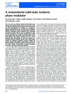
for some sensing the andgeometries, detectingitapplications, a to tunable whose operation frequencyIncan reconstructing is very difficult changeabsorber, the physical structure after fabrication. be tuned within a certain frequency range, is essential and necessary. Ho et al. introduced addition, for some sensing and detecting applications, a tunable absorber, whose operation electrothermally with an frequency can actuated be tuned microactuators within a certainintegrated frequency range, is Omega-ring essential and metamaterial necessary. Ho unit et al.cell introduced electrothermally integrated with an Omega-ring metamaterial to provide continuous tuning actuated [17], butmicroactuators the fabrication of this structure was complicated. In our unit cell to provide continuous tuning [17], but the fabrication this structure was complicated. previous work, a polarization-dependent tunable terahertz MAofbased on a graphene monolayerInwas our previous work, a polarization-dependent tunable terahertz MA based on is a graphene monolayer presented [18]. Nevertheless, acquiring a perfect monolayer graphene sheet still a challenge. was presented [18]. Nevertheless, acquiring a perfect monolayer graphene sheet is still a challenge. It has been verified that the absorption frequency of an MA based on liquid crystal (LC) can be It hastuned been verified that the absorption frequency of an MA based on birefringence liquid crystal (LC) can[19,20]. be dynamically in the terahertz region due to the voltage-dependent of LC dynamically tuned in the terahertz region due to the voltage-dependent birefringence of LC [19,20]. Based on this concept, a polarization-dependent LC tunable MA at terahertz frequencies based on Based on this concept, a polarization-dependent LC tunable MA at terahertz frequencies based on a a new metamaterial unit cell is proposed in this paper. The influence of the orientation on LC cells new metamaterial unit cell is proposed in this paper. The influence of the orientation on LC cells on on the absorber’s absorption spectrum in two orthogonal directions is theoretically investigated. It is the absorber's absorption spectrum in two orthogonal directions is theoretically investigated. It is shown that that a distinct absorption peak with bias voltage located is at 239.5 GHz TE-polarization shown a distinct absorption peaknowith no biasisvoltage located at for 239.5 GHz for andTE-polarization 306.6 GHz for TM-polarization. Moreover, it is experimentally demonstrated that, by controlling and 306.6 GHz for TM-polarization. Moreover, it is experimentally demonstrated the bias of LC molecules, the absorption peak can be tuned with a maximal that,voltage by controlling the bias voltage of LC molecules, the absorption peak can frequency be tuned tunability with a of 4.7% and 4.1% for TEand TM-polarization, respectively. maximal frequency tunability of 4.7% and 4.1% for TE- and TM-polarization, respectively. 2. Structure Design and Principle 2. Structure Design and PrincipleofofOperation Operation TheThe structure of the the of proposed polarization-dependent tunabletunable absorber is presented structure ofunit the cell unitofcell the proposed polarization-dependent absorber is presented in Figure 1. is This unit cell of is acomposed of a pair of printed metal layers printed onof the surfacequartz of in Figure 1. This unit cell composed pair of metal layers on the surface parallel parallel withthem, a voidwhich between whichwith is fully filled with a nematic liquid plates with quartz a voidplates between is them, fully filled a nematic liquid crystal. Thecrystal. metallic The metallic patterned layer at the upper surface of the quartz plate serves not only as a patterned layer at the upper surface of the quartz plate serves not only as a resonantresonant structure, structure, shows characteristics of polarization dependence, as electrode a top electrode of whole the which showswhich characteristics of polarization dependence, but alsobut as also a top of the whole tunable absorber. tunable absorber.
Figure 1. Schematic diagramofofaametamaterial metamaterial absorber absorber based (LC). Figure 1. Schematic diagram basedon onliquid liquidcrystal crystal (LC).
It is well known that LC materials are composed of anisotropic molecules and that the It is well known that LC materials are composed of anisotropic molecules and that the orientation orientation of LC molecules can be controlled with an external electrical field. Thus, by changing the of LC molecules can be controlled with an electrical field. Thus, bythe changing the bias voltage bias voltage between two metal layers, theexternal direction of LC molecules along electric field vector of between two metal layers, the direction of LC molecules along the electric field vector of the incident the incident wave, i.e., the permittivity of the LC layer, can be dynamically adjusted. To control the wave, i.e., theofpermittivity of without the LC layer, can abe dynamically adjusted. Topolyimide control the of LC direction LC molecules applying bias voltage, a thin layer of (Pi)direction is spanned molecules applying a bias voltage, a thin layer of polyimide is spanned on the inner on the without inner surface of both metal layers. In the unbiased state (ε⊥(Pi) ), due to the static action ofsurface the of both metalalignment layers. In layer, the unbiased ), due to the static action of the polymer alignment layer, polymer the longstate axis(εof molecules is parallel to the quartz surface. The bias ⊥ voltage, is applied the layers, rotatesThe the bias LC molecules, whichisprovides the the long axiswhich of molecules is across parallel tobiasing the quartz surface. voltage, which applied across permittivity ||) at saturationwhich state,provides while thethe direction of permittivity the LC molecules the maximal biasing layers, rotates(εthe LCthe molecules, maximal (ε|| ) atisthe perpendicular to thethe celldirection walls. Therefore, themolecules LC permittivity can be electronically saturation state, while of the LC is perpendicular to the cellvaried walls.between Therefore, these two states, i.e., Δε eff = ε|| − ε⊥, thus the absorption frequency of the absorber can be shifted. the LC permittivity can be electronically varied between these two states, i.e., ∆εeff = ε|| − ε⊥ , thus the Thefrequency geometrical ofcan the be unit-cell structure presented in Figure 1 are as follows: a = absorption of dimensions the absorber shifted. 460 μm, b = 35 μm, R = 135 μm, r = 100 μm, w = 45 μm, s = 15 μm, Hq1 = 350 μm, Hq2 = 1000 μm, and The geometrical dimensions of the unit-cell structure presented in Figure 1 are as follows: HLC = 45 μm. Both metal layers are made of a 0.5-μm-thick copper layer with a conductivity of σ =
a = 460 µm, b = 35 µm, R = 135 µm, r = 100 µm, w = 45 µm, s = 15 µm, Hq1 = 350 µm, Hq2 = 1000 µm, and HLC = 45 µm. Both metal layers are made of a 0.5-µm-thick copper layer with a conductivity of
Electronics 2018, 7, 27
3 of 10
σ = 5.8 × 1072018, S/m, plates are considered as a dielectric material with a relative permittivity Electronics 7, xand FOR quartz PEER REVIEW 3 of 10 of 3.78 and a dielectric loss tangent of 0.02. The absorptivity of an absorber can be determined 7 S/m, and areA, considered with a relative permittivity of by A5.8=× 10 1− where S11 , andasSa21dielectric denote material the absorptivity, reflection coefficient, |S11 |2 −quartz |S21 |2 ,plates 3.78 and a dielectric loss respectively. tangent of 0.02. Thethe absorptivity of anis absorber determined by and transmission coefficient, Since transmission equal to can zerobedue to the existence 2 2 2 = 1− | Sground | − | S | , where A, S 11, andcan S 21 be denote the absorptivity, reflection coefficient, and of theAcopper plate, the absorptivity simplified as A = 1 − S . | 11 | 11 21 transmission coefficient, respectively. Since the transmission is equal to zero due to the existence of
3. Simulated Results and Absorption Mechanisms
the copper ground plate, the absorptivity can be simplified as
A = 1− | S11 |2 .
The simulations were conducted by using the finite-element frequency-domain method, and the 3. Simulated Results and Absorption Mechanisms unit-cell boundary conditions were utilized in both the x and y directions. Meanwhile, the Floquet port condition was employed in the z-direction. According to ourfrequency-domain previously reported results The simulations were conducted by using the finite-element method, and[21], the LC material was assumed to be S200 in the simulations, where its permittivity in the unbiased the unit-cell boundary conditions were utilized in both the x and y directions. Meanwhile, thestate (ε⊥ ) and the port fullycondition biased state 2.47 and 3.06,According respectively. In the simulation, the loss Floquet was(εemployed in to the z-direction. to our previously reported || ) was set results [21],LC thelayer LC material was assumed to be S200 in the simulations, its permittivity in the tangent of the is set to 0.02. Moreover, in this study, the LC where is treated as a homogeneous unbiased (ε⊥) and theinfully biased state ||) was set to 2.47[22–24], and 3.06, the of material, whichstate is widely used the modeling of (ε LC-based devices andrespectively. the effectiveInindex simulation, the loss tangent of the LC layer is set to 0.02. Moreover, in this study, the LC is treated as the aligned nematic LC is given by [25] a homogeneous material, which is widely used in the modeling of LC-based devices [22–24], and ne nby o [25] the effective index of the aligned nematic LC is given
neff = p
n eff =
ne 2 sin2 θn+nno 2 cos2 θ e
2
o
(1)
(1)
2
2 2 where no and ne represent the ordinary and extraordinary respectively, and θ is the LC director n e sin θ + nindices, o cos θ angle. Since the LC is a nonmagnetic material, (1) can be rewritten by
where no and ne represent the ordinary and extraordinary indices, respectively, and θ is the LC director angle. Since the LC is a nonmagnetic material, ε⊥ ε// (1) can be rewritten by
ε=
2 ε⊥ sin2 θ + ε εε// cos θ
ε=
.
⊥ //
(2)
(2)
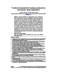
2 θ + εboth θ .and TM-polarized wave incidences, sin 2 for / / cos As shown in Figure 2, it can be noticedε ⊥that, TE-
the direction of the electric field vector in the LC layer is mainly parallel to the z-axis, which is As shown in Figure 2, it can be noticed that, for both TE- and TM-polarized wave incidences, perpendicular to the direction LC molecules. the is LCmainly permittivity to ε⊥ which in the initial the direction of the electricoffield vector in theHence, LC layer parallelistoequal the z-axis, is ◦ case (θ = 0 ). With the increase in bias voltage applied on the the LC permittivity to in the perpendicular to the direction of LC molecules. Hence, theLC LClayer, permittivity is equal to εincreased ⊥ ε|| ininitial the fully biased state, and the reorientation angle of the LC molecule gradually shifted toward case (θ = 0°). With the increase in bias voltage applied on the LC layer, the LC permittivity increased to ε||finally in the parallel fully biased state, and(θ the= reorientation angle of the LC molecule gradually the z-axis and was to the z-axis 90◦ ). shifted toward the z-axis and was finally parallel to the z-axis (θ = 90°).
Figure 2. Calculated results peak absorptionfrequency: frequency: (a) of of thethe electric field in the Figure 2. Calculated results forfor peak absorption (a)distribution distribution electric field in the LC layer under TE-polarized normal incidence 238.4 GHz;(b) (b)distribution distributionof ofthe the electric electric field field in LC layer under TE-polarized normal incidence at at 238.4 GHz; in the the LC layer under TM-polarized normal incidence at 313.2 GHz. LC layer under TM-polarized normal incidence at 313.2 GHz.
Electronics 2018, 7, 27 Electronics 2018, 7, x FOR PEER REVIEW
4 of 10 4 of 10
The absorption spectra for TE-polarized and TM-polarized normal incidence excitations for different LC2018, director angles, which demonstrateand the TM-polarized tunable performance of the proposed LC-based The absorption spectra for TE-polarized normal incidence excitations for Electronics 7, x FOR PEER REVIEW 4 of 10 metamaterial absorber, were calculated and theythe aretunable shownperformance in Figure 3.ofInthe Figure 3, it LC-based can be seen different LC director angles, which demonstrate proposed ◦shown TheLC absorption spectra for TE-polarized TM-polarized normal incidence for for absorber, were increases calculated and they in Figure 3. In Figure 3,excitations it can be seen that,metamaterial as the director angle from 0and toare 90 , the distinct peak absorption frequency different LC director angles, which demonstrate the tunable performance of the proposed LC-based that, as the LC director anglefrom increases 0 toGHz, 90°, the distinct peak absorption formax ) TE-polarized incidence changes 238.4from to 226.1 with a frequency tunability frequency (fmod = ∆f/f metamaterialincidence absorber, changes were calculated andtothey areGHz, shown in aFigure 3. In Figure 3, it(fcan beΔf/f seen TE-polarized from 238.4 226.1 with frequency tunability mod = max) of 5.1%. Meanwhile, a frequency tunability of 5.7% is achieved for TM-polarized incidence as the peak that, as the LC director angle increases fromof05.7% to 90°, achieved the distinct peak absorptionincidence frequencyasfor of 5.1%. Meanwhile, a frequency tunability for TM-polarized absorption frequency varies from 313.2 to 295.2 GHz.isMoreover, it can also be seen in Figure the 3 that, TE-polarized incidence changes GHz, with a frequency (fmodin = Δf/f max) peak absorption frequency variesfrom from238.4 313.2toto226.1 295.2 GHz. Moreover, it cantunability also be seen Figure 3 for both TE-polarized and TM-polarized incidence excitations, absorptivity remains higherasthan 90% of 5.1%. Meanwhile, a frequency tunability of 5.7% is achieved for TM-polarized incidence the that, for both TE-polarized and TM-polarized incidence excitations, absorptivity remains higher ◦ for TE-polarization), (except for the LC director angle of 0 so the proposed metamaterial absorber peak90% absorption from 313.2ofto0°295.2 GHz. Moreover, itsocan be seenmetamaterial in Figure 3 than (exceptfrequency for the LCvaries director angle for TE-polarization), thealso proposed possesses high absorption within entire tunable frequency region, absorptivity a promisingremains finding.higher that, for both TE-polarized andthe TM-polarized incidence excitations, absorber possesses high absorption within the entire tunable frequency region, a promising finding. than 90% (except for the LC director angle of 0° for TE-polarization), so the proposed metamaterial absorber possesses high absorption within the entire tunable frequency region, a promising finding.
Figure 3. 3. Simulated for different differentLC LCdirector director angles Figure Simulatedabsorption absorption spectra spectra of of absorber absorber for angles forfor (a) (a) thethe TE-polarized incident wave and theTM-polarized TM-polarized incident incident wave. TE-polarized incident wave and (b)(b)the wave. Figure 3. Simulated absorption spectra of absorber for different LC director angles for (a) the TE-polarized incident wave and (b) the TM-polarized incident wave.
To explore intrinsicmechanism mechanismof of the the absorber, absorber, the on on thethe To explore thethe intrinsic the surface surfacecurrent currentdistribution distribution patterned copper layer and the copper ground plate for the TE-polarized and TM-polarized normal explore the and intrinsic mechanism of the absorber, surface current on the patternedTocopper layer the copper ground plate for thethe TE-polarized and distribution TM-polarized normal incidence in and the unbiased state was calculated and is illustrated in TM-polarized Figure 4. patternedexcitations copper layer the copper ground plate for the TE-polarized and normal
incidence excitations in the unbiased state was calculated and is illustrated in Figure 4. incidence excitations in the unbiased state was calculated and is illustrated in Figure 4.
Figure 4. Simulated surface current distribution on (a) the patterned copper layer at 238.4 GHz Figure 4. Simulated surface current distribution on patterned copper layer 238.4 GHz Figure 4. Simulated surface current distribution (a) (a) thethe patterned copper layer at at 238.4 GHz under under TE-polarized incidence, (b) the copperonground plane at 238.4 GHz under TE-polarized under TE-polarized incidence, (b) the copper ground plane at 238.4 GHz under TE-polarized TE-polarized incidence, (b) the copper ground plane at 238.4 GHz under TE-polarized incidence, (c) incidence, (c) the patterned copper layer at 313.2 GHz under TM-polarized incidence, and (d) the the incidence, (c) the patterned layer TM-polarized at 313.2 GHz incidence. under TM-polarized (d) theplane copper ground plane 313.2copper patterned copper layer atat313.2 GHz under under TM-polarized incidence, and (d) incidence, the copperand ground copper ground plane at 313.2 GHz under TM-polarized incidence. at 313.2 GHz under TM-polarized incidence.
Electronics 2018, 7, 27
Electronics 2018, 7, x FOR PEER REVIEW
5 of 10
5 of 10
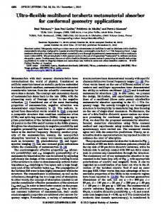
According to the results presented in Figure 4a, it is obvious that the surface current on the copper pattern flows parallel to the direction of the electric field vector of TE-polarized incident wave. According to the results presented in Figure 4a, it is obvious that the surface current on the As copper a result,pattern two electric dipole responses are excited the patterned layer. Moreover, the surface flows parallel to the direction of the in electric field vector of TE-polarized incident current on the copper ground plate shown in Figure 4b is the reverse of that in Figure 4a, as the magnetic wave. As a result, two electric dipole responses are excited in the patterned layer. Moreover, the response excited currents two4b metallic layers.ofFor TM-polarized surfaceiscurrent onby thecirculating copper ground platebetween shown inthe Figure is the reverse thatthe in Figure 4a, as incident wave, as shown isinexcited Figure by 4c,circulating four dipoles are excited, and electric response mainly the magnetic response currents between thethe two metallic layers. is For the contributed by coupling interaction between these dipoles. Similarly, the surface current on the copper TM-polarized incident wave, as shown in Figure 4c, four dipoles are excited, and the electric ground plane reversed, and the by magnetic response for TM-polarized wave is also response is is mainly contributed coupling interaction between these incident dipoles. Similarly, theexcited surfaceby combining thethe copper pattern withplane the copper plate. and the magnetic response for TM-polarized current on copper ground is reversed, incident wave is the alsoohmic excitedlosses by combining the copper pattern with copper Furthermore, at the patterned copper layer, asthe well as theplate. power loss density in Furthermore, the ohmic losses at the patterned copper layer, as well as the power losscalculated density the quartz plate and LC layer, for both the TE- and TM-polarized incident waves were theillustrated quartz plate and the LC dielectric layer, for loss bothdistribution the TE- and waveswith werethe andinare in Figure 5. The of TM-polarized the absorber isincident in agreement calculated and are illustrated in Figure The dielectric distribution the absorber is inby electric field distribution, and the ohmic loss 5. distribution at theloss pattern surface isofmainly determined agreement with the electric field distribution, and the ohmic loss distribution at the pattern surface the surface currents. In addition, it can be observed that most of the energy in the absorber is dissipated is mainly determined by the surface currents. addition, it can beunder observed the energy in the LC layer, which contributes most of the In power absorption boththat TE-most andof TM-polarized in the absorber is dissipated in the LC layer, which contributes most of the power absorption under normal incidences. Thus, the LC plays an important role not only in frequency tuning but also in the both TE- and TM-polarized normal incidences. Thus, the LC plays an important role not only in absorption of incident waves. frequency tuning but also in the absorption of incident waves.
Figure Calculatedresults resultsfor forpeak peakabsorption absorption frequency: frequency: (a) at at thethe Figure 5. 5. Calculated (a) distribution distributionofofsurface surfacelosses losses patterned copper layeratat238.4 238.4GHz, GHz,(b) (b)distribution distribution of dielectric dielectric power patterned copper layer powerloss lossdensity densityofofthe thequartz quartz plate 238.4GHz, GHz,(c) (c)distribution distribution of loss density of the LC layer at 238.4 GHz, GHz, (d) plate at at 238.4 of dielectric dielectricpower power loss density of the LC layer at 238.4 ofof dielectric (d) distribution distributionof ofsurface surfacelosses lossesatatthe thepatterned patternedcopper copperlayer layeratat313.2 313.2GHz, GHz,(e)(e)distribution distribution dielectric power density of quartz the quartz at 313.2 and (f) distribution of dielectric loss power lossloss density of the plateplate at 313.2 GHz,GHz, and (f) distribution of dielectric powerpower loss density density of the LC layer at 313.2 GHz. of the LC layer at 313.2 GHz.
4. Absorption Spectrum Dependence on Geometrical Parameters and Incident Angle 4. Absorption Spectrum Dependence on Geometrical Parameters and Incident Angle In this section, the effect of the structure geometry on the absorption spectrum is analyzed. We In this section, the effect of the structure geometry on the absorption spectrum is analyzed. suppose that only one parameter, e.g., the inner radius of the ring (r), the width of the vertical We suppose that only one parameter, e.g., the inner radius of the ring (r), the width of the vertical connecting bar (w), the width of the horizontal bar (b), or the gap between the horizontal bar and connecting bar (w), the width of the horizontal bar (b), or the gap between the horizontal bar and the the edge of the unit cell (s), is changed, while the other dimensions are kept the same. edge of The the unit cell (s),results is changed, while r,the kept theinsame. simulation for different w,other b, anddimensions s values areare presented Figure 6. As shown in Figure 6a, with the increase in r, the resonance frequencies for both TE- and TM-polarized incident excitations are redshifted. An LC circuit mode for this metamaterial absorber is given by [26]
Electronics 2018, 7, 27
6 of 10
The simulation results for different r, w, b, and s values are presented in Figure 6. As shown in Figure 6a, with the increase in r, the resonance frequencies for both TE- and TM-polarized incident excitations are redshifted. An LC circuit mode for this metamaterial absorber is given by [26] f= Electronics 2018, 7, x FOR PEER REVIEW
1 √ . 2π LC/2
(3) 6 of 10
The equivalent inductance L increases as r increases. It should be noticed that the increase in linewidth of metallic line leads to an increase in both1the equivalent inductance L and the equivalent f = inductance L is much stronger that the equivalent (3) capacitance C. However, the increase in equivalent 2π LC / 2 . capacitance C in this structure, as we mainly discussed the influence of equivalent inductance L in The equivalent L increases as r increases. It should be noticed increase in this section. According to inductance Equation (3), the increased L leads to a redshift of that the the resonance frequency. linewidth of metallic line leads to an increase in both the equivalent inductance L and the It can be seen in Figure 6a that the resonance frequency of TE-polarization, compared to that of equivalent capacitance C. However, the increase in equivalent inductance L is much stronger that TM-polarization, is more sensitive r, which is as because thediscussed resonance TE-polarization is mainly the equivalent capacitance C into this structure, we mainly theof influence of equivalent concentrated in the (Figure 4a); as result, (3), thethe resonance TE-polarization is inductance L ring in thisarea section. According to a Equation increased frequency L leads to a of redshift of the resonanceon frequency. It can be seen in Figure 6a that the resonance frequency of TE-polarization, more dependent r. compared that of TM-polarization, is more sensitive to absorption r, which is because the resonance In Figure 6b, to it is shown that, for TE-polarization, the peak shows a slightofblueshift TE-polarization is mainly concentrated in the ring area (Figure 4a); as a result, the resonance with the increase in w. This is because, in this case, w has little influence on the equivalent inductance frequency of TE-polarization is more dependent on r. L of the ring In section. However, forthat, TM-polarization, amplitude and frequency the absorption peak Figure 6b, it is shown for TE-polarization, the absorption peak shows aofslight blueshift are sensitive widthinw,w.which be explained by the factlittle thatinfluence equivalent inductance with to thethe increase This iscan because, in this case, w has on the equivalent L of the inductance L ofwith the ring However, vertical bar decreases the section. increase in w. for TM-polarization, amplitude and frequency of the absorption are sensitive to the w, which explained by the fact that Similarly, the peak increase in b leads towidth a decrease in can the be equivalent inductance L equivalent of the horizontal inductance L of the vertical bar decreases with the increase in w. bar. Hence, the resonance frequency of TM-polarization is blueshifted (Figure 6c). However, this does Similarly, the increase in b leads to a decrease in the equivalent inductance L of the horizontal not affectbar. theHence, equivalent inductance L of of theTM-polarization ring area, so the resonance frequency of TE-polarization the resonance frequency is blueshifted (Figure 6c). However, this remains the doessame. not affect the equivalent inductance L of the ring area, so the resonance frequency of remains same. The TE-polarization effect of the gap s onthe the absorption spectrum was also analyzed, and results are presented The effect of the gap s on the absorption spectrum was also analyzed, and results are presented in Figure 6d. As shown in Figure 6d, the resonance frequency of TE-polarization is independent of in Figure 6d. As shown in Figure 6d, the resonance frequency of TE-polarization is independent of the gap s.the However, with the increase in s, the resonance frequency of TM-polarization shows a slight gap s. However, with the increase in s, the resonance frequency of TM-polarization shows a blueshift,slight which is caused byis acaused decrease in equivalent inductance L. L. blueshift, which by a decrease in equivalent inductance
6. Simulated absorption spectrum dependence differentstructural structural parameters: (a)(a) thethe inner Figure 6.Figure Simulated absorption spectrum dependence onon different parameters: ring,width r, (b) the of vertical connecting bar, (c) the the width thethe horizontal bar, bar, b, radius ofinner ring,radius r, (b)of the ofwidth vertical connecting bar, w,w,(c) widthof of horizontal b, and (d) the gap between the horizontal bar and the edge of the unit cell, s. and (d) the gap between the horizontal bar and the edge of the unit cell, s.
Electronics 2018, 7, 27
7 of 10
Electronics Electronics 2018, 2018, 7, 7, xx FOR FOR PEER PEER REVIEW REVIEW
77 of of 10 10
In addition, the absorber structure was analyzed theoretically for oblique incidence.incidence. The absorption In In addition, addition, the the absorber absorber structure structure was was analyzed analyzed theoretically theoretically for for oblique oblique incidence. The The spectrum for oblique incidence under the TE-polarized incident wave is shown in Figure 7a. In this absorption spectrum for oblique incidence under the TE-polarized incident wave is shown in Figure absorption spectrum for oblique incidence under the TE-polarized incident wave is shown in Figure case, the magnetic field remains along the along y-axis andy-axis the direction of wave propagation is changed 7a. 7a. In In this this case, case, the the magnetic magnetic field field remains remains along the the y-axis and and the the direction direction of of wave wave propagation propagation is is by an angle ϕ with respect to the x and z-axes. Figure 7a shows a slight blueshift with the increase changed by an angle φ with respect to the x and z-axes. Figure 7a shows a slight blueshift with the changed by an angle φ with respect to the x and z-axes. Figure 7a shows a◦ slight blueshift with the in incident angle andangle remains above 0.9 for an0.9 incident angle up to 60 . Fortooblique incidence increase increase in in incident incident angle and and remains remains above above 0.9 for for an an incident incident angle angle up up to 60°. 60°. For For oblique oblique under a TM-polarized incident wave, where the electric field is aligned towards towards the y-axis and the incidence incidence under under aa TM-polarized TM-polarized incident incident wave, wave, where where the the electric electric field field is is aligned aligned towards the the y-axis y-axis wave propagation is changed by an angle ϕ with respect to x and z-axes, as presented in Figure 7b, and to and the the wave wave propagation propagation is is changed changed by by an an angle angle φ φ with with respect respect to xx and and z-axes, z-axes, as as presented presented in in ◦ the absorption is almost unchanged for incident angles up to 30 . However, with the continuous Figure Figure 7b, 7b, the the absorption absorption is is almost almost unchanged unchanged for for incident incident angles angles up up to to 30°. 30°. However, However, with with the the increase in incident angle, the absorptionthe decreases rapidly. Moreover, the increase in incident angle of continuous continuous increase increase in in incident incident angle, angle, the absorption absorption decreases decreases rapidly. rapidly. Moreover, Moreover, the the increase increase in in the TM-polarized wave leads to an obvious redshift of the absorption peak, and a frequency tunability incident angle of the TM-polarized wave leads to an obvious redshift of the absorption peak, and incident angle of the TM-polarized wave leads to an obvious redshift of the absorption peak, and aa ◦ , which represents another effective of 20.9% is tunability achieved by increasing the incident angle from 0the to 60 frequency of 20.9% is achieved by increasing incident frequency tunability of 20.9% is achieved by increasing the incident angle angle from from 00 to to 60°, 60°, which which method of modulating the proposed structure. represents represents another another effective effective method method of of modulating modulating the the proposed proposed structure. structure.
Figure 7.7.Simulated absorption spectra of absorber for differentdifferent incident angles for (a) the TE-polarized Figure Figure 7. Simulated Simulated absorption absorption spectra spectra of of absorber absorber for for different incident incident angles angles for for (a) (a) the the incident waveincident and (b) wave the TM-polarized incident wave.incident wave. TE-polarized and (b) the TM-polarized TE-polarized incident wave and (b) the TM-polarized incident wave.
5. 5. Experimental Experimental Results Results In In this this section, section, we we experimentally experimentally validate validate the the proposed proposed metamaterial metamaterial absorber absorber presented presented in in 2 2 Figure The structure was fabricated using 2 × 2 cm quartz substrates. To control the orientation 1. The structure was fabricated using 2 × 2 cm quartz substrates. To control the orientation of 2 Figure 1. The structure was fabricated using 2 × 2 cm quartz substrates. To control the orientation of molecules in unbiased state, inner surfaces of layers were covered by LC molecules in an unbiased state, thethe inner surfaces of metal layers were covered by polyimide (Pi) of LC LC molecules in an an unbiased state, the inner surfaces of metal metal layers were covered by polyimide polyimide (Pi) layers. created by glass micropearls with diameter alignment layers. TheThe LC LC cavity waswas created by placing thethe glass micropearls with thethe diameter of (Pi) alignment alignment layers. The LC cavity cavity was created by placing placing the glass micropearls with the diameter of 45 μm between two wafers, which were then sealed by a thin film of epoxy resin. Lastly, liquid 45 µm between two wafers, which were then sealed by a thin film of epoxy resin. Lastly, liquid crystals of 45 μm between two wafers, which were then sealed by a thin film of epoxy resin. Lastly, liquid crystals were thick cavity. The were inserted into a 45into µm athick cavity. fabricated sample issample shownis Figurein 8.Figure crystals were inserted inserted into a 45 45 μm μm thickThe cavity. The fabricated fabricated sample isinshown shown in Figure 8. 8.
Figure Figure 8. 8. Structure Structure of of fabricated fabricated metamaterial metamaterial absorber. absorber. Figure 8. Structure of fabricated metamaterial absorber.
The The measurement measurement setup setup is is presented presented in in Figure Figure 9. 9. The The free free space space measurement measurement method method was was The measurement setup is presented in Figure 9. The free space measurement method was adopted in the experiment. An antenna that was connected to the Agilent N5224A vector adopted in the experiment. An antenna that was connected to the Agilent N5224A vector network network adopted experiment. antenna that was to the Agilent N5224Ain network analyzer via VNA extenders VDI VNAX592 was used S-parameters the analyzer in viathe VNA extendersAn VDI VNAX592 wasconnected used to to measure measure S-parameters invector the frequency frequency analyzer via VNA extenders VDI VNAX592 was used to measure S-parameters in the frequency range range 220–325 GHz. Moreover, a pair of THz lens was utilized to focus the THz beam. range 220–325 GHz. Moreover, a pair of THz lens was utilized to focus the THz beam. 220–325 GHz. Moreover, a pair of THz lens was utilized to focus the THz beam.
Electronics 2018, 7, 27 Electronics 2018, 7, x FOR PEER REVIEW
8 of 10 8 of 10
Figure 9. Measurement setup.
The measured absorption spectra at unbiased and full biased states for TE- and TM-polarization are given in Figure 10. For TE-polarization, Figure 10a, the frequency of the measured absorption peak in an unbiased state is in agreement with that in the simulation. However, in a biased state under TE-polarized incidence, the frequency of the measured absorption peak is higher than that in the simulation. TM-polarization, Figure 10b, there is a difference Figure Measurement setup. Figure 9. 9. For Measurement setup. between the frequencies of the measured and simulated absorption peaks in an unbiased state, The measured absorption spectra sample at unbiased and full biased states for TEwhich might be caused by an inaccurate size, especially for structural parameters suchand as The measured absorption spectra at unbiased and full biased states for TE- and TM-polarization TM-polarization areconnecting given in Figure 10. the Forwidth TE-polarization, the width of vertical bar w and of horizontalFigure bar b. 10a, the frequency of the are given in Figure 10. For TE-polarization, Figure 10a, the frequency of the measured absorption measured absorption peak inwas an evaluated unbiased by state is in agreement with atthat in thebias simulation. The frequency tunability measuring the absorption different voltages peak in an unbiased state is in agreement with that in the simulation. However, in a biased state However, a biased state under TE-polarized the frequency of the LC in layer. In Figure 11a, when the biasincidence, voltage increases fromof0the to measured 10 V, the absorption resonance under TE-polarized incidence, the frequency of the measured absorption peak is higher than that peak is higher than that in the simulation. FortoTM-polarization, Figure 10b,a frequency there is a difference frequency of TE-polarization shifts from 239.5 228.1 GHz (redshift), with tunability in the simulation. For TM-polarization, Figure 10b, there is a difference between the frequencies between the frequencies of the measured and simulated absorption peaks in an unbiased state, of 4.7%. For TM-polarization, as shown in Figure 11b, a frequency tunability of 4.1% is achieved of the measured and simulated absorption peaks in an unbiased state, which might be caused by whichthe might be caused byfrequency an inaccurate sample size, especially for structural parameters suchand as when absorption peak decreases from 306.6 to 294 GHz. Moreover, for both TEan inaccurate sample size, especially for structural parameters such as the width of vertical connecting the width of vertical connecting bar w and the width horizontal barvoltages. b. TM-polarization, measured absorption is higher than of 80% for all bias bar w and the width of horizontal bar b. The frequency tunability was evaluated by measuring the absorption at different bias voltages of the LC layer. In Figure 11a, when the bias voltage increases from 0 to 10 V, the resonance frequency of TE-polarization shifts from 239.5 to 228.1 GHz (redshift), with a frequency tunability of 4.7%. For TM-polarization, as shown in Figure 11b, a frequency tunability of 4.1% is achieved when the absorption peak frequency decreases from 306.6 to 294 GHz. Moreover, for both TE- and TM-polarization, measured absorption is higher than 80% for all bias voltages.
Figure 10. Simulated Simulated and and measured measured absorption absorption in in unbiased unbiased and and full full biased biased states states for for (a) the TE-polarized incident wave and (b) the TM-polarized incident wave. wave.
The frequency tunability was evaluated by measuring the absorption at different bias voltages of the LC layer. In Figure 11a, when the bias voltage increases from 0 to 10 V, the resonance frequency of TE-polarization shifts from 239.5 to 228.1 GHz (redshift), with a frequency tunability Figure Simulated and measured unbiased and full biased states for is (a)achieved the of 4.7%. For10.TM-polarization, as shownabsorption in Figurein11b, a frequency tunability of 4.1% TE-polarized incident wave and (b) the TM-polarized incident wave. when the absorption peak frequency decreases from 306.6 to 294 GHz. Moreover, for both TE- and TM-polarization, measured absorption is higher than 80% for all bias voltages.
Electronics 2018, 7, 27 Electronics 2018, 7, x FOR PEER REVIEW
9 of 10 9 of 10
Figure bias voltages forfor (a) (a) the the TE-polarized incident wavewave and Figure 11. 11. Measured Measuredabsorption absorptionfor fordifferent different bias voltages TE-polarized incident (b) incident wave. andthe (b)TM-polarized the TM-polarized incident wave.
6. Conclusions In this metamaterial absorber based on on LC LC intended for this paper, paper,aatunable tunablepolarization-dependent polarization-dependent metamaterial absorber based intended THz frequencies is presented, and both and experiment were carried outcarried to investigate for THz frequencies is presented, andsimulation both simulation and experiment were out to the proposed structure. Intensive absorption were experimentally detected at 239.5 GHz for investigate the proposed structure. Intensivepeaks absorption peaks were experimentally detected at a239.5 TE-polarized and at 306.6 GHzand for aatTM-polarized wave, when no biaswave, voltagewhen was applied. GHz for wave a TE-polarized wave 306.6 GHz for a TM-polarized no bias The absorption mechanism the absorber was analyzed terms of the current distribution voltage was applied. The of absorption mechanism of theinabsorber wassurface analyzed in terms of the and power loss distribution, and the effects of various geometrical parameters on absorption were surface current distribution and power loss distribution, and the effects of various geometrical investigated. Most importantly, adjusting theMost bias importantly, voltage of theby LCadjusting layer from 0 to 10 V, a frequency parameters on absorption wereby investigated. the bias voltage of the tunability of 4.7% wave andoffrequency tunability of 4.1%wave for a and TM-polarized LC layer from 0 tofor 10the V, aTE-polarized frequency tunability 4.7% for the TE-polarized frequency wave were of experimentally demonstrated.wave Therefore, presented tunable polarization-dependent tunability 4.1% for a TM-polarized were the experimentally demonstrated. Therefore, the metamaterial absorber has great potential inmetamaterial selective spectral detection, polarization presented tunable polarization-dependent absorber has great potentialmultiplexing, in selective and THzdetection, polarization imaging. multiplexing, and THz polarization imaging. spectral polarization Acknowledgments: This Thiswork work was supported byNational the National Natural Foundation of China (No. Acknowledgments: was supported by the Natural ScienceScience Foundation of China (No. 51607050), 51607050), Fundamental Research Funds for the Central Universities (No. JD2017JGPY0006), and Science the Sichuan Fundamental Research Funds for the Central Universities (No. JD2017JGPY0006), and the Sichuan and Technology Project (No. 2016GZ0250). Science and Support Technology Support Project (No. 2016GZ0250). conceived and wrote thethe paper; Yujiao Lu, Zhiping Yin, Author Author Contributions: Contributions: Guangsheng GuangshengDeng Dengand andJun JunYang Yang conceived and wrote paper; Yujiao Lu, Zhiping and Hongbo Lu performed the experiments; Weien Lai guided the experimental design and analyzed the data; Yin, and Hongbo Lu performed the experiments; Weien Lai guided the experimental design and analyzed the Aifeng Yang revised the whole manuscript; Yang Ye, Dayong Liu, and Baihong Chi gave important guidance on data; Aifeng Yang revised the whole manuscript; Yang Ye, Dayong Liu, and Baihong Chi gave important fabrication work. guidance on fabrication work. Conflicts of Interest: The authors declare no conflict of interest. Conflicts of Interest: The authors declare no conflict of interest.
References References 1. 1. 2. 2. 3. 3.
4. 4. 5. 5. 6. 6. 7. 7. 8.
Tonouchi, M. Cutting-edge terahertz technology. Nat. Photonics 2007, 1, 97–105. [CrossRef] Tonouchi,M.M.Development Cutting-edgeand terahertz Photonics 2007, 1, 97–105. Hangyo, future technology. prospects ofNat. terahertz technology. Jpn. J. Appl. Phys. 2015, 54, 120101. Hangyo, M. Development and future prospects of terahertz technology. Jpn. J. Appl. Phys. 2015, 54, 120101. [CrossRef] Ferrari, L.; Zhang, X.; X.; Liu,Liu, Z. Hyperbolic metamaterials and their applications. Prog. Ferrari, L.; Wu, Wu,C.; C.;Lepage, Lepage,D.;D.; Zhang, Z. Hyperbolic metamaterials and their applications. Quantum Electron. 2015, 40, 1–40. Prog. Quantum Electron. 2015, 40, 1–40. [CrossRef] Jung, J.Y.; J.Y.; Lee, Lee, J.; J.; Choi, Choi, D.G.; D.G.; Choi, Choi, J.H.; J.H.; Jeong, Jeong, JJ H.; H.; Lee, Lee, E.S.; Wavelength-selective infrared infrared Jung, E.S.; Neikirk, Neikirk, D.P. D.P. Wavelength-selective metasurface absorber absorber for for multispectral multispectral thermal thermal detection. detection. IEEE IEEE Photonics Photonics J.J. 2015, 2015, 7, 7, 1–10. 1–10. [CrossRef] metasurface Chen, Q.; Q.; Hu, Hu, X.; L.; Yu, Yu, Y.; Y.; Cumming, Cumming, D.R. D.R. Nanophotonic Nanophotonic image image sensors. sensors. Small Chen, X.; Wen, Wen, L.; Small 2016, 2016, 12, 12, 4922–4935. 4922–4935. Landy, N.I.; Sajuyigbe, S.; Mock, J.J.; Smith, D.R.; Padilla, W.J. Perfect metamaterial absorber. Phys. Rev. [CrossRef] [PubMed] Lett. 2008, 100, 207402. Landy, N.I.; Sajuyigbe, S.; Mock, J.J.; Smith, D.R.; Padilla, W.J. Perfect metamaterial absorber. Phys. Rev. Lett. Zhu, 100, J.; Ma, Z.; Sun, W.; Ding, F.; He, Q.; Zhou, L.; Ma, Y. Ultra-broadband terahertz metamaterial 2008, 207402. [CrossRef] [PubMed] absorber. Appl. Phys.W.; Lett. 2014,F.;105, Zhu, J.; Ma, Z.; Sun, Ding, He,021102. Q.; Zhou, L.; Ma, Y. Ultra-broadband terahertz metamaterial absorber. La Spada, L.; Vegni, L. Metamaterial-based Appl. Phys. Lett. 2014, 105, 021102. [CrossRef]wideband electromagnetic wave absorber. Opt. Express 2016, 24, 5763–5772.
Electronics 2018, 7, 27
8. 9. 10. 11. 12. 13. 14. 15. 16. 17.
18. 19. 20. 21. 22. 23.
24. 25. 26.
10 of 10
La Spada, L.; Vegni, L. Metamaterial-based wideband electromagnetic wave absorber. Opt. Express 2016, 24, 5763–5772. [CrossRef] [PubMed] Shen, Y.; Pei, Z.; Pang, Y.; Wang, J.; Zhang, A.; Qu, S. An extremely wideband and lightweight metamaterial absorber. J. Appl. Phys. 2015, 117, 224503. [CrossRef] [PubMed] Yahiaoui, R.; Guillet, J.P.; de Miollis, F.; Mounaix, P. Ultra-flexible multiband terahertz metamaterial absorber for conformal geometry applications. Opt. Lett. 2013, 38, 4988–4990. [CrossRef] [PubMed] Wang, B.X.; Zhai, X.; Wang, G.Z.; Huang, W.Q.; Wang, L.L. Design of a four-band and polarization-insensitive terahertz metamaterial absorber. IEEE Photonics J. 2015, 7, 1–8. [CrossRef] Liu, S.; Zhuge, J.; Ma, S.; Chen, H.; Bao, D.; He, Q.; Zhou, L.; Cui, T.J. A bi-layered quad-band metamaterial absorber at terahertz frequencies. J. Appl. Phys. 2015, 118, 245304. [CrossRef] Chu, J. K.; Wang, Z.W.; Guan, L.; Liu, Z.; Wang, Y.L.; Zhang, R. Integrated polarization dependent photodetector and its application for polarization navigation. IEEE Photonics Technol. Lett. 2014, 26, 469–472. Sakurai, A.; Zhao, B.; Zhang, Z.M. Effect of polarization on dual-band infrared metamaterial emitters or absorbers. J. Quant. Spectrosc. Radiat. Transfer 2015, 158, 111–118. [CrossRef] Wang, B.X.; Wang, L.L.; Wang, G.Z.; Huang, W.Q.; Zhai, X. Broadband, polarization-insensitive and wide-angle terahertz metamaterial absorber. Phys. Scr. 2014, 89, 115501. [CrossRef] Kim, Y.J.; Kim, J.M.; Yoo, Y.J.; Tuong, P.V.; Zheng, H.Y.; Rhee, J.Y.; Lee, Y.P. Dual-absorption metamaterial controlled by electromagnetic polarization. JOSA B 2014, 31, 2744–2747. [CrossRef] Ho, C.P.; Pitchappa, P.; Lin, Y.S.; Huang, C.Y.; Kropelnicki, P.; Lee, C. Electrothermally actuated microelectromechanical systems based omega-ring terahertz metamaterial with polarization dependent characteristics. Appl. Phys. Lett. 2014, 104, 161104. [CrossRef] Deng, G.S.; Chen, P.; Yang, J.; Yin, Z.P.; Qiu, L.Z. Graphene-based tunable polarization sensitive terahertz metamaterial absorber. Opt. Commun. 2016, 380, 101–107. [CrossRef] Shrekenhamer, D.; Chen, W.C.; Padilla, W.J. Liquid crystal tunable metamaterial perfect absorber. Phys. Opt. 2012, 110, 177403. Isi´c, G.; Vasi´c, B.; Zografopoulos, D.C.; Beccherelli, R.; Gaji´c, R. Electrically tunable critically coupled terahertz metamaterial absorber based on nematic liquid crystals. Phys. Rev. Appl. 2015, 3, 064007. [CrossRef] Lu, H.B.; Jing, S.C.; Xia, T.Y.; Yang, J.; Yin, Z.P.; Deng, G.S. Measurement of LC dielectric constant at lower terahertz region based on metamaterial absorber. IEICE Electron. Express 2017, 14, 20170469. [CrossRef] Zhang, F.L.; Zhao, Q.; Gaillot, D.P.; Zhao, X.P.; Lippens, D. Numerical investigation of metamaterials infiltrated by liquid crystal. JOSA B 2008, 25, 1920–1925. [CrossRef] Sasaki, T.; Noda, K.; Kawatsuki, N.; Ono, H. Universal polarization terahertz phase controllers using randomly aligned liquid crystal cells with graphene electrodes. Opt. Lett. 2015, 40, 1544–1547. [CrossRef] [PubMed] Chikhi, N.; Lisitskiy, M.; Papari, G.; Tkachenko, V.; Andreone, A. A hybrid tunable THz metadevice using a high birefringence liquid crystal. Sci. Rep. 2016, 6, 34536. [CrossRef] [PubMed] Khoo, I.C. Liquid Crystals: Physical Properties and Nonlinear Optical Phenomena; John Wiley & Sons: New York, NY, USA, 2007; pp. 36–63. Ye, Y.Q.; Jin, Y.; He, S. Omnidirectional, polarization-insensitive and broadband thin absorber in the terahertz regime. JOSA B 2010, 27, 498–504. [CrossRef] © 2018 by the authors. Licensee MDPI, Basel, Switzerland. This article is an open access article distributed under the terms and conditions of the Creative Commons Attribution (CC BY) license (http://creativecommons.org/licenses/by/4.0/).