Progress In Electromagnetics Research B, Vol. 22, 341–357, 2010
TUNABLE METAMATERIAL DESIGN COMPOSED OF TRIANGULAR SPLIT RING RESONATOR AND WIRE STRIP FOR S- AND C- MICROWAVE BANDS C. Sabah Johann Wolfgang Goethe University Physikalisches Institut Max-von-Laue-Strasse 1, D-60438, Frankfurt am Main, Germany Abstract—In this paper, we study tunable metamaterial structures whose unit cell has triangular split ring resonator and wire strip for S- and C-microwave bands. Three types of new metamaterials, concentric and non-concentric configurations, are designed, and their electromagnetic response is investigated. Constitutive and S parameters are computed using retrieval algorithm to demonstrate the properties of the proposed new metamaterial designs. In addition, the electric field distribution on the metallic parts of the structure is illustrated for one design of the each sample. It is shown that the studied new metamaterials exhibit double negative properties in the frequency region of interest. The main advantage of this study based on the proposed structures is having the tunability in terms of the substrate thickness and the possibility of pronounced loss reduction.
1. INTRODUCTION The concept of metamaterial (MTM) started with the suggestion of the physics scientist V. Veselago in 1967 [1]. Veselago suggested a new type of material which has simultaneously negative permittivity and permeability, and he presented general properties of electromagnetic wave propagation in such a material. He theoretically created a lossless MTM and showed the extraordinary properties of this material which is not found in nature. Then, Pendry and his coworkers presented their studies about the negative permittivity and the negative permeability as in [2] and [3]. They stated that an array of metallic wires with suitably chosen spacing and radius can be constructed to get negative Corresponding author: C. Sabah (
[email protected]).
342
Sabah
exhibition in the permittivity in 1996 [2], and a metallization of split rings can be manufactured for negative permeability in 1999 [3]. Later then, Smith and his colleagues demonstrated a new MTM that shows simultaneously negative permittivity and permeability and carried out microwave experiments to test its unusual properties in 2000 [4]. The first experiment showing negative refraction was performed using a metamaterial consisting of a two-dimensional array of repeated unit cells of copper strips and split ring resonators in 2001 by Shelby et al. [5]. Several theoretical and experimental works have been studied by researchers on MTMs and their potential applications [6–22]. The design of MTM based on shape and geometry is the most interesting work among the others [13–22]. Especially, the design of split rings which provide the negative permeability is very important to construct a new type of MTMs. Numerous types of different ring and ring-like structures such as circular, square, Ω-shaped, U-shaped, S-shaped and others are used to create new MTMs (see [18] for a brief history). In the light of the known structures, new MTMs using triangular shaped ring are constructed which has not been studied before 2008. Although there are now few studies about the triangular shaped resonators in the literature [23–30], the first study of the MTM with triangular resonator was conducted by Sabah [23, 24] and some researchers has already used and cited the mentioned first work in their studies [28–30]. In this paper, new MTMs comprised of triangular split ring resonator (TSRR) and wire strip (WS) are constructed and analyzed. In the analysis, retrieval method is used for the calculation of the effective material parameters. There types MTM structures with TSRR and WS are investigated. Two non-concentric configurations, vertex to vertex and base to base combinations, respectively, and one concentric arrangement are designed and demonstrated. From the simulation results, the real part of the refractive index is found to be negative at frequencies where both real parts of the permittivity and permeability are negative and overlap each other at the same frequency band. All numerical simulations show that the proposed new MTMs are well designed and they can be manufactured for several potential applications in the microwave region with the advantages of tunability and enunciable loss reduction. In addition, they can also be used to design new MTMs for the low and high frequency regimes. 2. ANALYSIS AND SIMULATION As it is well known, the combination of split ring resonator (SRR) and WS structures are commonly used to engineer artificial MTMs showing unconventional properties not found in nature. In the literature,
Progress In Electromagnetics Research B, Vol. 22, 2010
(a)
(b)
343
(c)
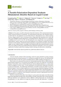
Figure 1. Three different types of metamaterial unit cells. (a) MTM1, (b) MTM2, (c) MTM3. several types of SRRs are proposed for the realization purpose in which TSRR is one of them. Figure 1 illustrates the geometry of the unit cells comprised of TSRR and WS for three different structures. The first one is arranged to have a vertex to vertex configuration and the second one is modified to have a base to base arrangement as shown in Figure 1. The third structure is formed from nested TSRR which is considered to have a similar configuration as in the concentric loop-like (circular, square, or etc.) split ring resonator. Two types of materials, FR4 (with relative permittivity εr = 4.4 and loss tangent δ = 0.02) and Rogers RT/duroid 5880 (tm) high frequency laminate (with relative permittivity εr = 2.2 and loss tangent δ = 0.0009), are used as a substrate for each simulations. TSRR and WS are made of copper with conductivity of 5.8 × 10⁷ S/m and thickness of 35 µm. The width of all TSRR is 0.4 mm. TSRR is located on one face of the substrate and WS is etched on its opposite face. WS is continuous along the whole substrate in all structures, as shown in Figure 1. Metamaterial unit cells are designed and simulated using the commercial software package based on finiteelement method. Each configuration is placed in a two-port waveguide formed by a pair of both perfect electric conductor (PEC) and perfect magnetic conductor (PMC) walls. All substrates with TSRR and WS are centered in the waveguide and it is excited by an electromagnetic wave with the propagation vector k in y-direction, the electric field vector E in x-direction, and the magnetic field H in z-direction. The corresponding open, electric, and magnetic boundary conditions related with the propagation and field vectors, respectively, are used in the simulation. To show the physical properties of the designed structures, S
344
Sabah
parameters for a single unit cell is calculated with the mentioned boundaries along the wave propagation. Next, the effective material parameters can be extracted from the S parameters as [13, 14, 16] s 2 (1 + S11 )2 − S21 (1) z= 2 (1 − S11 )2 − S21 · ¸ ¢ 1 ¡ 1 −1 2 2 (2) n= cos 1 − S11 + S21 kd 2S21 where z and n indicate the wave impedance and refractive index, respectively. Then, the electric permittivity and magnetic permeability can be computed from the equations of ε = n/z and µ = nz. In addition, the transfer matrix method is also used in the numerical calculations to compute the absorption (or loss) which is given as follows: ¡ 2 ¢ 2 A = 1 − S11 + S21 . (3) Details of the transfer matrix method can be found in References of [12, 16, 23]. Note that, it is worth mentioning the key advantage of the mentioned method is that it gives directly the absorption as given in Equation (3) when the reflection and transmission of the electromagnetic wave passing through the system are known. Therefore, the above absorption equation will be used in the numerical simulations to observe the loss of the proposed structures. 2.1. Simulation of MTM1 In the first simulation, MTM1 shown in Figure 1(a) is simulated using the mentioned substrates (FR4 and RT/duroid 5880) with varying thicknesses. The width of WS is 0.5 mm. The base and the height of TSRR are 7.794 mm and 6.75 mm, respectively. The gap in each TSRR is 0.3 mm and the separation between TSRR is 0.4 mm. The S parameters for MTM1 are computed and the effective material parameters are extracted by means of the obtained S parameters (detail discussion for S and constitute parameters can be found in Section 2.3). Figure 2 shows the results obtained from the simulation for MTM1. In this figure, the amplitude (in dB) and the phase of the transmission, real part of the refractive index, and the absorption are illustrated. As it is seen, all parameters are frequency dependent complex functions which satisfy certain requirements of causality. The dip in the phase of the transmission indicates the presence of negative region (or the location of the resonance in terms of the frequency) which can easily be observed from the figure. Note that, the minimum value in the amplitude of the logarithmic transmission also defines the
Progress In Electromagnetics Research B, Vol. 22, 2010
345
location of the resonance or the negative region in addition to the dip in the phase of the transmission. One can see that from the figure, these two (dip and minimum) are very close to each other. For example, the resonance for MTM1 comprised of RT/duroid 5880 substrate with the thickness of 0.125 mm occurs at 5.423 GHz. The transmission minimum for this structure is at 5.373 GHz. One can see that the resonance occurs at the frequency which is very close to the frequency location where the logarithmic transmission has a minimum value. In addition, the other MTM structures also show the same behavior. In Figure 2, the simulation results are obtained for different values of the substrate thickness as 0.125, 0.25, and 0.5 mm. The solid curves correspond to RT/duroid 5880 and the dotted curves correspond to FR4. Red curves indicate the substrate thickness of 0.125 mm, black curves 0.25 mm, and blue curves 0.5 mm. One of the proposed structures (FR4 with 0.5 mm) shows the electromagnetic behavior in the S-band and the rest are operating in C-band. As the substrate thickness decreases from 0.5 mm to 0.125 mm, the minimum of the transmission and the dip of its phase shift from the lower to higher frequencies for both FR4 and RT/duroid 5880. It also yields shifting in the negative refractive index in the same direction. It is obvious that one can easily obtain minimization or maximization in the frequency shifting as desired/required amount by tuning the substrate thickness and also by changing the material of the substrate used. For example, 17.7% maximization can be obtained in the location of the negative region (or resonance frequency) by using FR4 with 0.125 mm instead of 0.5 mm. In addition, 15.68% minimization can be achieved by using FR4 with 0.25 mm instead of RT/duroid 5880 substrate with the same thickness. Essentially, in this MTM, the whole system works as in the conventional nested SRR based MTMs in which these kinds of structures can be considered √ as a resonant LC circuit with the resonance frequency of ωr = 1/ LC. The capacitance in the conventional nested SRR based MTMs is formed by edge coupling between the inner and outer ring. When the thickness of the substrate is decreased, the capacitance will decrease, and thus the resonance frequency will increase. Then, the minimum of the transmission and the dip of its phase will shift to the higher frequencies. Here, the capacitance is formed via TSRRs and WS by coupling with each other and the MTM structure exhibits the same performance as in the conventional nested SRR based MTMs. As it is observed here, the increment in the substrate thickness contributes to the capacitance of the overall system in the directly proportional way. Furthermore, the loss of the structure can be reduced by using Rogers high frequency laminates instead of FR4 material. Moreover,
346
Sabah
Figure 2. Magnitude and phase of the transmission, real part the refractive index, and the loss for MTM1. The solid curves show the results for RT/duroid 5880 and the dotted curves for FR4. Red curves illustrate the results for the substrate thickness of 0.125 mm, black curves for 0.25 mm, and blue curves for 0.5 mm. the loss can be reduced by minimization of the substrate thickness. But, the loss level is almost constant in the case of the Rogers laminate used. Figure 3 shows the variation of the resonance frequency with the substrate thickness for both FR4 and RT/duroid 5880 materials. As it is seen from the figure, the resonance frequency decreases nonlinearly when the substrate thickness increases for the both materials. In addition, the resonance frequency occurs in the low (high) part of the studied frequency spectrum when FR4 (RT/duroid 5880) substrate is used. In Figure 4, the electric field is presented for MTM1 with 0.25 mm thick FR4 substrate in which the color map shows the electric field amplitude. The electric field is strong at the apex and at the gaps as it is expected. Thus, around the apex and the gaps of TSRR; and around the center and ends of WS, the electric field is resonantly enhanced. Not that, the electric field distribution in WS is very strong across the gaps and the apexes because of the strong coupling at the sharp edges
Progress In Electromagnetics Research B, Vol. 22, 2010
347
Figure 3. Resonant frequency versus substrate thickness. The squares and circles shows the values used in the simulation of MTM1.
Figure 4. Electric field distribution for MTM1. and gaps of the structure. 2.2. Simulation of MTM2 As a second simulation, MTM2 shown in Figure 1(b) is simulated. All dimensions of the structure are the same with the previous example. The only difference between MTM1 and MTM2 is the position of TSRR and the thickness of the substrate. In the first one, TSRRs are located to have a vertex to vertex configuration while in this case they are organized to form a base to base configuration. The structure here is especially prepared from the thick Rogers duroid material, relative to the previous example, to observe the capability of the designed MTM. The plots of the amplitude and the phase of the transmission, the loss factor, and the resonant frequency are presented for MTM2 in Figure 5. RT/duroid 5880 substrate is used in the simulation. According to the results obtained, the minimum of the transmission, the dip of the transmission phase, and the peak of the loss factor shift to the right side of the spectrum when the substrate thickness increases. Also, the resonant frequency increases with the increasing values of the
348
Sabah
Figure 5. Amplitude and phase of the transmission, the loss factor, and the resonant frequency for MTM2. substrate thickness and shows nonlinear behavior. Note that, the data for the resonant frequency versus substrate thickness is plotted with the fitted curve. The structure with the studied parameters in this example exhibits the opposite behavior as compared with the previous one because of the thick substrate and orientation of TSRRs. Here, increasing the substrate thickness affects the coupling between TSRRs and WS in an inversely proportional way. Thus, the capacitance of the whole structure decreases and hence the resonance frequency increases. Consequently, the minimum of the transmission and the dip of its phase shift to the higher frequencies. Note that, the orientation of TSRRs also affects the capacitance, however this effect is more than as in the previous MTM because of the base to base arrangement. Figure 6 shows the electric field amplitude for MTM2 with 2.5 mm RT/duroid 5880. The electric field is strong at the vertex, the base and the gaps of TSRRs. Thus, the electric field is formed strongly around the vertex, the base and the gaps of TSRR. It is also strong around the center and ends of WS because of the same reason explained in the previous section for Figure 4.
Progress In Electromagnetics Research B, Vol. 22, 2010
349
Figure 6. Electric field distribution for MTM2. 2.3. Simulation of MTM3 In the last simulation, the concentric MTM3 which is shown in Figure 1(c) is simulated. The dimensions of WS are 0.3 mm × 7.3 mm × 0.017 mm, respectively. The base and the height of TSRRs are given as: 7.98 mm and 6.91 mm for outer TSRR; 2.942 mm and 2.548 mm for inner TSRR. The gap in each TSRR is 0.5 mm and the separation between TSRR is 3.603 mm from the vertex of outer TSRR to the base of inner TSRR. Figure 7 indicate the S parameters and the effective material parameters for the MTM3 with 1.0 mm thick FR4 substrate. Note that, similar results and observations as in the previous two designs were also obtained for MTM3 but only S parameters and the effective material parameters are presented in this section. For passive materials, real part of the wave impedance and imaginary part of the refractive index must be greater than zero. The wave impedance and refractive index satisfy this condition for our configuration. According to the theory of metamaterials, the real parts of the permittivity and permeability must be negative. Negative real parts for the permittivity and permeability are also observed for the proposed structure and the negative permittivity has wider frequency band than the permeability. Furthermore, the permittivity and permeability show Drude and Lorentz response behavior for the studied frequency region, respectively. Here, the dip in the phase of S21 is observed at 3.225 GHz. The real part of the permittivity is negative up to 4.75 GHz which is the electric plasma frequency obtained from the simulation, and the negative real part of the permeability lies between 3.305 GHz and 3.710 GHz which are the resonance and magnetic plasma frequencies. The negative band for the refractive index approximately lies between the resonance and magnetic plasma frequencies because the negative permeability span also defines the band for negative refraction. The structure has 34% loss because of the substrate material and metallic inclusions. This loss can be reduced by reduction of the substrate thickness or by changing the
350
Sabah
Figure 7. Magnitude and phase of S parameters, real and imaginary parts of the wave impedance, refractive index, permittivity, permeability and the loss for MTM3.
Progress In Electromagnetics Research B, Vol. 22, 2010
351
substrate material. Note that, the area of the unit cell of MTM3 is 63 mm2 . Therefore, there is a size reduction in area of about 7.5% if one compares the proposed MTM3 with Reference 31 which provides a comparison of MTM composed of TSRRs. Thus, the size reduction is always possible in this kind of structures but one should be careful about the design frequency. In this case, the resonance frequency or the position of the refractive index in terms the frequency is shifted. To keep the resonance frequency fixed, one has to make optimization in the metallic parts of the structure in addition to the scaling in the area of the substrate. For this MTM3, the electric field which is shown with the color map is presented in Figure 8. In this configuration, the electric field is not strong at the vertex and at the gaps. Here, it is strong at the legs of TSRR and at WS except the ends of it. The electric field is enhanced in almost all of WS and some parts of the legs of TSRRs, in this configuration. Tuning analysis is also applied for MTM3 and Figure 9 shows the frequency response of the amplitude and the phase of the transmission when the substrate thickness is tuned mechanically. FR4 material is used with 0.25 mm, 0.5 mm, and 1.0 mm, separately. The same copper inclusions as in the previous MTM3 example are used for TSRR and WS. It is observed that the simulated MTM structure operates in the microwave S-band and the frequency response of the structure shifts to the lower frequencies when the thickness of the substrate is increased. The related phase information of the transmission also satisfies this observation. The tuning response of MTM3 is the same as in MTM1 and opposite of MTM2 as it is expected because of the nested configuration of the structure.
Figure 8. Electric field distribution for MTM3.
352
Sabah
Figure 9. Amplitude (in dB) and phase (in radian) of the transmission for MTM3. 3. SUMMARY, DISCUSSION, AND CONCLUSION We have studied the tunable MTMs formed from FR4 and RT/duroid 5880 substrates with different thicknesses consisting of TSRR and WS. A new geometry for the ring resonator, TSRR, was introduced. Three types of MTM structures are designed and modeled. S parameters and then retrieved effective material parameters are computed for all MTMs. The electric field distribution on the TSRR and WS by indicating their contributions is also presented for one of each design. The contribution of WS to the electric filed is very strong in the last structure among the others. Furthermore, the dip in the phase of S21 is observed for the designed MTMs and the negative frequency region is pointed. The refractive index confirms the pointed negative frequency region and the negative real part of the refractive index occurs around this frequency region. Also, the real part of the refractive index is negative at frequencies where both the real parts of the permittivity and permeability are negative. It can be said that from the simulation results, the permittivity and permeability show Drude and Lorentz response behavior respectively in the studied frequency region as it is expected. At this point, it can be concluded that a computer based algorithm can be prepared based on Drude and Lorentz models of the proposed structures for further investigations and it is now under consideration. Regarding the non-concentric configurations, it is relatively easy to fabricate because it does not require nested structures. Also, it is easy to control the structure’s geometry to realize wide- or narrowband MTMs according to the potential applications and it allows for a larger degree of design freedom with respect to the spatial separation of the ring resonator and the wire strip systems. It is clear that the
Progress In Electromagnetics Research B, Vol. 22, 2010
353
electric field is mostly concentrated at the TSRR’s gaps of the nonconcentric configurations. The electric field is also localized at the gaps of the concentric one, but localization is not as strong as the nonconcentric configurations. Therefore one can be consider using split regions to achieve tunability from the TSRR structures by loading capacitances instead of gap regions. In this case, it is possible to have another tunable MTMs based on the changing the magnetic resonance frequency and the effective permeability. In addition, the high intensity of the electric field in the gaps makes the resonance frequency very sensitive to small changes in the dielectric permittivity and this yields a considerable nonlinearity behavior by adding some materials near the gaps of TSRRs. In general, the resonance frequencies vary significantly with change of the substrate and its thickness. Note that, closed triangular ring resonator with WS is also simulated to observe the existence of the resonant frequency of the MTM structures. In that case, the magnetic resonance is disappeared and only the electrical resonance is remained. Here, nonlinear decrease and increase can be observed in the resonance frequency when the substrate type and thickness are changed. The results show that effective tunable MTMs can be realized by tuning the properties of the substrate. It is also possible to control (shifting, modifying, locating, and etc.) the negative frequency region and bandwidth of the refractive index to the desired frequency bands by using the proposed tunable structures. In addition, a low-loss MTM structures can easily be created and the simulations indicate that the losses can be decreased without compromising the performance of the device. Furthermore, MTMs based on the conventional SRR (circular and square SRR) and WS structures with the proposed values here are simulated for the comparison purpose. Then, the loss factor of the conventional MTMs has compared with the suggested MTMs (data not shown). It is observed that the suggested MTMs provide a gain up to 20%. Tunability for the MTM structures can be achieved using dynamic and non-dynamic methods in which it can be determined by varying their mechanical, electric, magnetic, optical properties, and etc. Some of them can be listed as: Connecting diodes or capacitance, adding liquid crystals, changing the temperature, and varying the substrate thickness [31–35]. In all of them, the resonant frequency changes nonlinearly with the variation of the interested parameter. In this study, tunability is achieved by using a non-dynamic way in which it requires several MTM slabs in practice and therefore it is feasible. If the results obtained in this study are compared with the literature, one can see that they have also non-linear characteristic when the thickness of the
354
Sabah
substrate is tuned mechanically. Consequently, this study shows how to obtain the tunability in metamaterials using a mechanical method and it can be used in many applications where several MTMs and tunability is required at the same time. It can be concluded that the designed MTMs exhibit double negative properties in the microwave S- and C-bands. It means that the modeled structures are well designed and successfully work around the operation frequency. As a result, proposed novel MTMs can provide new ways to design, characterize, and manufacture new MTMs in the microwave, millimeter wave, and optical frequency regions. All these structures can be used to construct new functional devices such as electromagnetic filters, antennas, and etc. They have been already used in some application such as antennas and waveguides. As a future work, we will improve the proposed structures to be able to use them in appropriate applications. Experimental study, symmetric edge coupled, broadside, and complementary MTMs comprised of TSRR configurations have been already under investigation. REFERENCES 1. Veselago, V. G., “The electrodynamics of substances with simultaneously negative values of ε and µ,” Soviet Physics Uspekhi, Vol. 10, 509–514, 1968. 2. Pendry, J. B., A. J. Holden, W. J. Stewart, and I. Youngs, “Extremely low frequency plasmons in metallic mesostructures,” Physical Review Letters, Vol. 76, 4773–4776, 1996. 3. Pendry, J. B., A. J. Holden, D. J. Robbins, and W. J. Stewart, “Magnetism from conductors and enhanced nonlinear phenomena,” IEEE Transactions on Microwave Theory and Techniques, Vol. 47, 2075–2084, 1999. 4. Smith, D. R., W. J. Padilla, D. C. Vier, S. C. Nemat-Nasser, and S. Schultz, “Composite medium with simultaneously negative permeability and permittivity,” Physical Review Letters, Vol. 84, 4184–4187, 2000. 5. Shelby, R. A., Smith D.R., and Schultz S., “Experimental verification of a negative index of refraction,” Science, Vol. 292, 77–79, 2001. 6. Ziolkowski, R. W. and E. Heyman, “Wave propagation in media having negative permittivity and permeability,” Physical Review E, Vol. 64, 056625.1–056625.15, 2001. 7. Tretyakov, S. A., “Meta-materials with wideband negative per-
Progress In Electromagnetics Research B, Vol. 22, 2010
8. 9.
10. 11. 12.
13. 14.
15. 16. 17.
18. 19.
355
mittivity and permeability,” Microwave and Optical Technology Letters, Vol. 31, 163–165, 2001. Kong, J. A., “Electromagnetic wave interaction with stratified negative isotropic media,” Progress In Electromagnetics Research, Vol. 35, 1–52, 2002. Engheta, N, “Metamaterials with negative permittivity and permeability: Background, salient features, and new trends,” IEEE MTT-S International Microwave Symposium Digest, Vol. 1, 187–190, 2003. Chew, W. C., “Some reflections on double negative materials,” Progress In Electromagnetics Research, Vol. 51, 1–26, 2005. Sabah, C. and S. Uckun, “Electromagnetic wave propagation through the frequency-dispersive and lossy double-negative slab,” Opto-Electronics Review, Vol. 15, 133–143, 2007. Sabah, C. and S. Uckun, “Scattering characteristics of the stratified double-negative stacks using the frequency dispersive cold plasma medium,” Zeitschrift f¨ ur Naturforschung A, Vol. 62a, 247–253, 2007. Ziolkowski, R. W., “Design, fabrication, and testing of double negative metamaterials,” IEEE Transaction on Antennas and Propagation, Vol. 51, 1516–1529, 2003. Chen, X., T. M. Grzegorczyk, B.-I. Wu, J. Pacheco, and J. A. Kong, “Robust method to retrieve the constitutive effective parameters of metamaterials,” Physical Review E, Vol. 70, 016608.1–016608.7, 2004. Linden, S., C. Enkirch, M. Wegner, J. Zhou, T. Koschny, and C. M. Soukoulis, “Magnetic response in metamaterials at 100 THz,” Science, Vol. 306, 1351–1353, 2004. Smith, D. R., D. C. Vier, T. Koschny, and C. M. Soukoulis, “Electromagnetic parameter retrieval from inhomogeneous metamaterials,” Physical Review E, Vol. 71, 036617.1–036617.11, 2005. Aydin, K., K. Guven, M. Kafesaki, C. M. Soukoulis, and E. Ozbay, “Investigation of magnetic resonances for different splitring resonator parameters and designs,” New Journal of Physics, Vol. 7, 168.1–168.15, 2005. Engheta, N. and R. W., Ziolkowski, Metamaterials — Physics and Engineering Explorations, Wiley — IEEE Press, Piscataway, NJ, 2006. Aydin, K. and E. Ozbay, “Identifying magnetic response of split-ring resonators at microwave frequencies,” Opto-Electronics Review, Vol. 14, 193–199, 2006.
356
Sabah
20. Liu, Y., N. Fang, D. Wu, C. Sun, and X. Zhang, “Symmetric and antisymmetric modes of electromagnetic resonators,” Applied Physics A — Materials Science & Processing, Vol. 87, 171–174, 2007. 21. Chen, H.-T., J. F. O’Hara, A. J. Taylor, R. D. Averitt, C. Highstrete, M. Lee, and W. J. Padilla, “Complementary planar terahertz metamaterials,” Optics Express, Vol. 15, 1084–1095, 2007. 22. Gundogdu, T. F., M. G¨okkavvas, K. Guven, M. Kafesaki, C. M. Soukoulis, and E. Ozbay, “Simulation and micro-fabrication of optically switchable split ring resonators,” Photonics and Nanostructures — Fundamental and Applications, Vol. 5, 106– 112, 2007. 23. Sabah, C., “Analysis, Applications, and a Novel Design of Double Negative Metamaterials,” PhD Thesis, University of Gaziantep, Gaziantep, Turkey, 2008. 24. Sabah, C. and S. Uckun, “Triangular split ring resonator and wire strip to form new metamaterial,” Proceedings of XXIX General Assembly of the International Union of Radio Science, Chicago, Illinois, USA, August 2008. 25. Sabah, C., A. O. Cakmak, E. Ozbay, and S. Uckun, “Transmission measurement of a new metamaterial sample with negative refraction index,” Physica B: Condensed Matter, Vol. 405, 2955– 2958, 2010. 26. Zhu, C., C. H. Liang, and L. Chen, “A novel left-handed material composed of triangular open-loop resonators,” International Workshop on Metamaterials, 188–190, November 2008. 27. Zhu, C., J.-J. Ma, L. Chen, and C.-H. Liang, “Negative index metamaterials composed of triangular open-loop resonator and wire structures,” Microwave and Optical Technology Letters, Vol. 51, 2022–2025, 2009. 28. Jalali, M., T. Sedghi, and Y. Zehforoosh, “Miniaturization of waveguides dual band antenna using TSRR-WS metamaterials,” International Journal of Computer and Electrical Engineering, Vol. 1, 1793–8163, 2009. 29. Jalali, M., T. Sedghi, and M. Shokri, “A novel metamaterial SRR for waveguide antenna,” Mediterranean Microwave Symposium (MMS), 1–4, November 2009. 30. Vidyalakshmi, M. R. and S. Raghavan, “A CAD model of triangular split ring resonator based on equivalent circuit approach,” Applied Electromagnetics Conference (AEMC), 1–4, December 2009.
Progress In Electromagnetics Research B, Vol. 22, 2010
357
31. Sheng, Z. and V. V. Varadan, “Tuning the effective properties of metamaterials by changing the substrate properties,” Journal of Applied Physics, Vol. 101, 014909.1–014909.7, 2007. 32. Zhao, Q., L. Kang, B. Du, B. Li, J. Zhou, H. Tang, X. Liang, and B. Zhang, “Electrically tunable negative permeability metamaterials based on nematic liquid crystals,” Applied Physics Letters, Vol. 90, 011112.1–011112.3, 2007. 33. Driscoll, T., G. O. Andreev, D. N. Basov, S. Palit, S. Y. Cho, N. M. Jokerst, and D. R. Smith, “Tuned permeability in terahertz split-ring resonators for devices and sensors,” Applied Physics Letters, Vol. 91, 062511.1–062511.3, 2007. 34. Chen, J.-Y., W.-L. Chen, J.-Y. Yeh, L.-W. Chen, and C.C. Wang, “Comparative analysis of split-ring resonators for tunable negative permeability metamaterials based on anisotropic dielectric substrates,” Progress In Electromagnetics Research M, Vol. 10, 25–38, 2009. 35. Wang, J., S. Qu, J. Zhang, H. Ma, Y. Yang, C. Gu, X. Wu, and Z. Xu, “A tunable left-handed metamaterial based on modified broadside-coupled split-ring resonators,” Progress In Electromagnetics Research Letters, Vol. 6, 35–45, 2009.