A Two Loop Fuzzy Controller for Goal Directed Navigation of Mobile Robot Umar Farooq1, Syed Omar Saleh2, Ghulam Abbas3, Muhammad Usman Asad4, Faiqa Rafiq5 1,2,4,5
Department of Electrical Engineering University of The Punjab Lahore 3 Lyon Institute of Nanotechnology (INL) CPE Lyon France 1
[email protected],
[email protected],
[email protected],
[email protected], 5
[email protected]
Abstract—This paper describes the design of a two loop fuzzy controller for goal directed navigation of a differentially driven mobile robot in unknown indoor environments. The first loop is responsible for finding a collision free path amongst obstacles while second loop uses this information to steer the mobile robot towards the target in absence of nearby obstacles. The fuzzy controller is designed and visualized with the help of Fuzzy Logic Toolbox in MATLAB environment where its membership functions and rules are tuned to have satisfactory real time results on an inexpensive test bed of two AT89C52 microcontrollers. The real time results obtained in indoor environment containing obstacles validate the proposed controller for goal directed navigation. Index Terms—Goal directed navigation, collision avoidance, fuzzy logic controller, wheeled mobile robot, MATLAB fuzzy logic toolbox, AT89C52 microcontroller
I. INTRODUCTION Navigation can be defined as the ability of mobile robot to reach the target without hitting the obstacles in its path. The task of navigation can be accomplished either with the help of classical controllers or by employing intelligent techniques. The choice between the two types of controllers depends upon the environment. The classical controllers can perform well in the environment for which they are designed. However, their performance is degraded in the presence of uncertainties. On contrary, intelligent controllers are quite capable to handle the noisy and changing environment conditions. Amongst various intelligent techniques, fuzzy logic is used in this research owing to its powerful feature of translating expert knowledge to precise control commands. Many researchers have used fuzzy logic to develop controllers for mobile robot navigation with behavior based strategy. The behavior based approach divides the task of navigation into several smaller sub tasks such as hurdle avoidance, wall following, goal seeking etc that results in simplified formulation of fuzzy rule base for the individual behaviors and outputs from these behaviors are then combined according to a control law to generate the motion commands for the robot. This control law is defined in [1] as priority based switching scheme that activates only one behavior at a time for robot navigation and has been employed in [2] for planetary exploration by a mobile robot. This scheme, though accomplishes the navigation task, may perform poor in certain situations e.g., when the target is located to the right of
978-1-4673-4451-7/12/$31.00 ©2012 IEEE
frontal obstacle and hurdle avoidance behavior directs the robot to the left thereby impeding the progress of target reaching behavior. The alternative to this control law has been employed in [3-4] which combines the outputs from different behaviors using a pre-determined weighting factor assigned to each behavior. However, the performance of such control law may deteriorate if the outputs from multiple behaviors are in direct conflict with each other e.g., if hurdle avoidance behavior asks the robot to go left upon detecting a frontal obstacle and goal seeking behavior directs the robot to go right towards the target, then combined result may lead the robot to collide with the obstacle. To overcome such constraints, various fuzzy fusion methodologies are proposed [5-12]. The context dependent blending in [5] uses fuzzy logic to select an appropriate behavior depending upon the current situation the robot is facing e.g., the robot is set to go with the same weights for hurdle avoidance and target reaching behaviors until a situation arises that demands the priority to be assigned to one of the two behaviors. Such a situation will occur when hurdle happens to be in the very near region, then hurdle avoidance behavior gets priority. The same contextual reasoning is employed in [6] to adjust the weights dynamically for blending the robot behaviors in order to navigate on challenging terrain. Thus in behavior based navigation; the main problem is to combine the outputs from individual behaviors to generate a smooth collision free path between source and destination. This paper proposes a two loop fuzzy controller as an alternative to behavior based controller for mobile robot navigation in unknown indoor environments. The controller waits for the determination of collision free path in first loop and passes this information onto second loop to direct the robot towards target by avoiding the nearby obstacles. Being a cascaded controller, this will take longer time to make an inference as opposed to parallel execution of several behaviors in behavior based controller but it will eliminate the need of finding the dynamic weighting factors for individual behaviors. After tuning its membership functions, rule base and visualizing the control surfaces using Fuzzy Logic Toolbox of MATLAB, the controller is implemented in real time using inexpensive AT89C52 microcontrollers with a machine cycle of 1µs. The real time results obtained with this nominal speed in the presence of static obstacles validate the proposed controller for goal directed navigation.
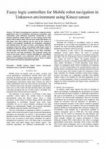
In the sections that follow; mobile robot architecture, design of fuzzy logic controller and experimental results are presented. II. MOBILE ROBOT ARCHITECTURE A differential drive robotic vehicle with all sides measuring 45cm and having height of 35cm is fabricated for experimentation. Two gear motors each having 300 rpm are used for powering the wheels while two caster wheels are attached for support. Three SRF05 ultrasonic sensors are mounted on the front side of the robot with the angular spacing of 45o and linear spacing of 22cm between them. These sensors are used to measure the distance between the robot and the obstacles in the environment. In order to compute the distance, the senor sends an 8 cycle burst of ultrasound having frequency of 40kHz after a pulse with short duration of 10µs is applied to its trigger pin. At the same time, the sensor raises its echo line high and waits for the echo. Upon receiving the echo, the sensor lowers its echo line. Thus the width of the echo line pulse is directly proportional to the distance between the robot and the obstacle [13]. A CMPS03 compass is also mounted on the robot to measure heading angle of the robot. The compass uses the Philips KMZ51 magnetic field sensor to detect the Earths magnetic field. The compass provides the output in the form of PWM signal and I2C interface. The width of PWM signal is measured in present work which is directly proportional to the robot heading. The width of this signal varies from 1ms (0o) to 36.99ms (359.9o) with 100µs/o being the resolution [14]. The robot uses two inexpensive AT89C52 microcontrollers having 8 kilo bytes of flash memory, 256 bytes of random access memory, 32 input/output lines and 5 interrupts [15]. One of the microcontrollers is responsible for gathering distance information from ultrasonic sensors and executing the first loop of fuzzy logic controller. The other microcontroller reads the heading information from the compass, executes the second loop of fuzzy logic controller an issues commands to left and right motors. The interface between the microcontroller and motor is an L298N IC. Two such ICs are employed one for each left and right motor. A single L298N IC contains two H-bridges, each having a current carrying capacity of 2A, which are connected in parallel in this work to prevent the IC from being damaging in case if the load demand is increased [16]. The isolation between the microcontroller and L298N is provided with the help of 4N25 opto-couplers. The designed wheeled mobile robot equipped with sensors and necessary hardware is shown in Fig. 1. III. FUZZY CONTROLLER DESIGN The goal directed navigation of mobile robot is achieved with the help of a two loop fuzzy logic controller. The first fuzzy loop processes the information from three ultrasonic sensors to find crisp values for left and right motors. These computed values correspond to collision free movement of mobile robot amongst obstacles and are passed onto a secod fuzzy loop where these values are used along with the heading information to generate the final motion commands for robot. The block diagram of the controller is shown in Fig. 2.
Fig. 1. Experimental wheeled mobile robot
LM
RM
F I R S T L O O P
Mobile Robot LS
CS
HA RS
Fuzzification
Rule Base Evaluation
Defuzzification
S E C O N D
Rule Base Evaluation
L O O P
Defuzzification
Fuzzification
Fig. 2. Block diagram of two loop fuzzy logic controller
A. Fuzzification The input to the first fuzzy loop is the distance information from three ultrasonic sensors namely Left Sensor (LS), Center Sensor (CS) and Right Sensor (RS). The distance measured by each sensor is described by three fuzzy sets namely Near, Med
and Far having triangular membership functions as shown in Fig. 3 with the universe of discourse for each sensor being in the range [20, 80]. The lower and upper limits on range are found during experimentation. The outputs from this fuzzy loop are the speed commands for left and right motors and are described by linguistic variables PreLM and PreRM respectively. The prefix ‘Pre’ is used in these linguistic variables to clarify that these are not the final motion commands for the robot. Both of these linguistic variables are described by three fuzzy sets namely Slow, Med and Fast with triangular membership functions as shown in Fig. 4. The universe of discourse for these linguistic variables is in range [0, 100]. The defuzzified values corresponding to PreLM and PreRM are passed onto second fuzzy loop. Here these crisp values are fuzzified into two regions namely Small and Large. The lesser number of regions or fuzzy sets are selected on trial basis to check the effectiveness of reduced rule base fuzzy logic controller. These fuzzy sets are shown in Fig. 5. At the same time, heading error, which will also act as an input to the second fuzzy loop, is computed as the difference between the current robot heading and the target angle. This heading error is described by the linguistic variable HE and is fuzzified into three regions namely Negative, Zero and Positive as show in Fig. 6. The universe of discourse for heading error is scaled in range [-100,100]. The outputs from second fuzzy loop are described by the linguistic variables LM and RM corresponding to speed of left and right motors. These variables are described by two fuzzy sets namely Slow and Fast with the universe of discourse being in the range [0,100] which actually describes the on time of PWM signal to control the speed of DC motors. These fuzzy sets are shown in Fig. 7. The triangular membership functions are used to represent each fuzzy set as these are not computationally complex. Fuzzy Rule Base Twenty seven rules are defined for finding a collision free path in first fuzzy loop while twelve rules in the second fuzzy loop ensures the goal directed navigation. These rules are finalized after satisfactory results are obtained in real time. The rule base of second fuzzy loop is reduced experimentally in an effort to compare the performance of reduced rule base controller with larger rule base controller. The rule base for first fuzzy loop is shown in Table 1 while the ruble base of second fuzzy loop is listed in Table 2.
Fig. 4. Fuzzy sets for PreLM in first fuzzy loop
Fig. 5. Fuzzy sets for PreLM in second fuzzy loop
B.
Fig. 6. Fuzzy sets for HE in second fuzzy loop
Fig. 7. Fuzzy sets for LM in second fuzzy loop
Fig. 3. Fuzzy sets for LS in first fuzzy loop
TABLE I.
RULE BASE FOR FIRST FUZZY LOOP
LS Near
CS Near
RS Near
LM Slow
RM Slow
Near
Near
Med
Fast
Slow
Near
Near
Far
Fast
Slow
Near
Med
Near
Fast
Slow
Near
Med
Near
Fast
Slow
Near
Med
Far
Fast
Slow
Near
Far
Near
Fast
Slow
Near
Far
Med
Fast
Slow
Near
Far
Far
Fast
Slow
Med
Near
Near
Slow
Fast
Med
Near
Near
Slow
Fast
Med
Near
Med
Fast
Slow
Med
Near
Far
Fast
Slow
Med
Med
Near
Slow
Fast
Med
Med
Med
Fast
Slow
Med
Med
Far
Fast
Med
Med
Far
Near
Slow
Fast
Med
Far
Med
Fast
Med
Med
Far
Far
Fast
Med
Far
Near
Near
Slow
Fast
Far
Near
Med
Slow
Fast
Far
Near
Far
Fast
Slow
Far
Med
Near
Slow
Fast
Far
Med
Med
Med
Fast
Far
Far
Near
slow
Fast
Far
Far
Med
Med
Fast
Far
Far
Far
Fast
Fast
TABLE II. PreLM
PreRM
method finds the geometrical center of the aggregated fuzzy sets using the following equation: 100
LM
(1)
¦ P out ( Z i )
i 1
Where i=1 and i=100 are the minimum and maximum values of the output linguistic variables in first and second fuzzy loops i.e., PreLM, PreRM, LM and RM. The variable Z i represents ith input value of a particular output linguistic variable Z while P out (Z i ) is the degree of membership of Z at ith input. Z o is the crisp value that is equal to the duty cycle of PWM signal. D. Fuzzy Controller Implementation Keeping in view the limited random access memory of AT89C52 microcontroller, the fuzzy loops are implemented as C programs in separate microcontrollers using Keil µVision development platform. To prevent floating point calculations, the degree of belongingness of all the linguistic variables is scaled in range [0, 100]. Due to RAM constraints, the range of output linguistic variables is scaled in range [0, 50]. The upper bound 50 is the length of array holding char values that are actually the degree of memberships of output linguistic variable corresponding to its universe of discourse. After defuzzification process, the crisp values are multiplied by a factor of 2 to yield the speed commands for the motors. The block diagram of fuzzy controller implementation is shown in Fig. 8. Left Sensor
RULE BASE FOR SECOND FUZZY LOOP HE
¦ Z i P out ( Z i )
i 1 100
Zo
PC
AT89C52 Microcontroller
RM
Small
Small
Neg
Slow
Fast
Small
Small
Zero
Slow
Fast
Small
Small
Pos
Slow
Fast
Small
Large
Neg
Slow
Fast
Small
Large
Zero
Slow
Fast
Small
Large
Pos
Slow
Fast
Large
Small
Neg
Fast
Slow
Large
Small
Zero
Fast
Slow
Large
Small
Pos
Fast
Slow Fast
Large
Large
Neg
Slow
Large
Large
Zero
Fast
Fast
Large
Large
Pos
Fast
Slow
C. Defuzzification The defuzzification to generate the crisp values in both the loops is achieved using Center of Area (COA) method. This
Center Sensor
Right Sensor
Left Motor
Motor Driver AT89C52 Microcontroller
Right Motor
Motor Driver
Fig. 8. Fuzzy controller implementation
Compass
IV. RESULTS AND DISCUSSIONS Experimentation of the proposed controller is carried out using the designed mobile robot in unknown indoor environment containing static obstacles. During the first experimental run, the target is set at an angle of 75o and robot is allowed to move with an initial heading of 180o. The robot traces a solid white path while heading towards the target. The results of this test run are shown in Fig. 9. The dotted path in Fig. 9 (b) is obtained with first fuzzy loop alone which is only responsible for finding a collision free path amongst obstacles with no target information. With the same target angle of 75o, robot is set to go with an initial angle of 225o. The results of this test run are shown in Fig. 10. The dotted paths in Fig. 10(b) are traced by the robot with first fuzzy loop only. The dotted paths differ from the solid paths as the robot has no destination in mind and therefore it will wander in the environment by avoiding the obstacles. Figures 11 and 12 show the resultant path traced by the robot with a target angle of 45o and initial heading angles of 180o and 90o respectively.
(a)
(b) Fig. 10. Testing of proposed controller with target angle set at 75o and initial heading being 225o
(a)
Fig. 11. Testing of proposed controller with target angle set at 45o and initial heading being 180o (b) Fig. 9. Testing of proposed controller with target angle set at 75o and initial heading being 180o
Fig. 12. Testing of proposed controller with target angle set at 45o and initial heading being 90o
V. CONCLUSIONS In this paper, design and implementation of a two loop fuzzy controller as an alternative to behavior based controller for goal directed navigation of mobile robot is presented. The controller is designed in such a way as to eliminate the process of finding the optimum weighting factors that determine the efficiency of the behavior based controller. However, the speed of proposed controller is lower than the behavior based controller which executes several robot behaviors in a concurrent fashion. MATLAB Fuzzy Logic Toolbox is used in designing the fuzzy controller and its implementation is realized on cost effective and readily available AT89C52 microcontrollers. The proposed controller is validated through experimentation in indoor environment with no prior information of obstacles using a differentially driven wheeled mobile robot. REFERENCES [1] R. A. Brooks, “A robust layered control system for a mobile robot,” IEEE Journal of Robotics and Automation, vol. 2, pp. 14-23, Feb 1986. [2] E. Gat, R. Desai, R. Ivlev, J. Loch and D. P. Miller, “Behavior control for robotic exploration of planetary surfaces,” IEEE Transactions on Robotics and Automation, vol. 10, pp. 490-503, Aug 1994.
[3] R. C. Arkin, “Motor schema-based mobile robot navigation,” International Journal of Robotic Research, vol. 8, no. 4, pp. 92112, 1989. [4] O. Khatib, “Real time obstacle avoidance for manipulators and mobile robots,” International Journal of Robotic Research, vol. 5, no. 1, pp. 90-98, 1986. [5] A. Saffiotti, “The uses of fuzzy logic in autonomous robot navigation,” Journal of Soft Computing, vol. 1, no. 4, pp. 180197, 1997. [6] H. Seraji and A. Howard, “Behavior based robot navigation on challenging terrain: a fuzzy logic approach,” IEEE Transactions on Robotics and Automation, vol. 18, no. 3, pp. 308-321, June 2002. [7] E. Aguirre and A. Gonzalez, “Fuzzy behaviors for mobile robot navigation: design, coordination and fusion,” International Journal of Approximate Reasoning, vol. 25, pp. 255-289, 2000. [8] S. G. Goodridge, M. G. Kay and R. C. Luo, “Multilayered fuzzy behavior fusion for reactive control of an autonomous mobile robot,” Proc. IEEE International Conference on Fuzzy Systems, Barcelona Spain, 1997, pp. 579-584. [9] W. Li, “Fuzzy logic based reactive behavior control of an autonomous mobile system in unknown environments,” Engineering Applications of Artificial Intelligence, vol. 7, no. 5, pp. 521-531, 1994. [10] P. Rusu, E. M. Petriu, T. E. Whalen, A. Cornell and H. J. W. Spoelder, “Behavior based neuro-fuzzy controller for mobile robot navigation,” IEEE Transactions on Instrumentation and Measurement, vol. 52, no. 4, pp. 1335-1340, Aug 2003. [11] B. Qing-yong, L. Shun-ming, S. Wei-yan and A. Mu-jin, “A Fuzzy behavior based architecture for mobile robot navigation in unknown environments,” Proc. International Conference on Artificial Intelligence and Computational Intelligence, Nov 2009, pp. 257-261. [12] W. Dongshu, Z. Yusheng and S. Wenjie, “Behavior based hierarchical fuzzy control for mobile robot navigation in dynamic environment,” Proc. Chinese Control and Decision Conference, 2011, pp. 2419-2424. [13] SRF05 Technical Documentation, [Online]. Available: http://www.robot-electronics.co.uk/htm/srf05tech.htm [14] CMPS03 Technical Documentation, [Online]. Available: http://www.robot-electronics.co.uk/htm/cmps3tech.htm [15] 8-bit Microcontroller with 8K Bytes Flash, [Online]. Available: http://www.atmel.com/Images/doc0313.pdf [16] Dual Full Bridge Driver, [Online]. Available: http://www.sparkfun.com/datasheets/Robotics/L298_H_Bridge. pdf