3D visualization in spatial planning and especially in landscape planning is ... way workflow from raw data to 3D models and demonstrates the combination of .... with the latest generation of GIS software Geo DBMS such as Oracle Spatial it.
A two-way workflow for integrating CAD, 3D visualization and spatial analysis in a GIS environment Dirk TIEDE and Thomas BLASCHKE
1
Introduction
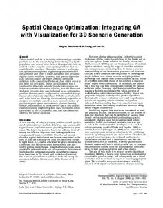
3D visualization in spatial planning and especially in landscape planning is widely established (ERVIN, 2001; EGGER et al., 2002; APPLETON & LOVETT, 2003). Its potential to provide a relatively realistic impression of a project serves the needs of decision makers but also those of the citizens affected (residents, certain stakeholders). Visual communication is an increasingly common part of environmental decision-making, being used to facilitate dialogue between policymakers and non-experts, increase understanding, and thereby improve the decisions made. GIS-based landscape visualisation is one method of producing images for consultation exercises and continuing advances in technology allow expansion into new areas such as the visualisation of rural landscapes and scenario techniques (APPLETON & LOVETT, 2003; TRESS & TRESS, 2003). This chapter highlights recent developments and describes a workflow in which visualisation is not an end in itself but it is a mean to communicate (geo)graphically and results of this communication process can be included in designing new versions within a planning process. We focus on very recent GIS developments but the workflow should not be technology driven. The authors carefully obey that there is considerable feeling that we should not allow ourselves to be guided simply by what the technology can do. Instead, we should carefully assess whether each of these increases in capability can enhance the usefulness of visualisations (ERVIN, 2001; APPLETON & LOVETT, 2003). The weakness of pure 3D visualization lies in the fact that analyses going beyond pure visualization techniques are missing. In fact, analysis is the domain of Geographical Information Systems (GIS). But only with the newest commercial GIS solutions is it possible to bring these two worlds together. The latest generation of GI-Systems is able to import realistic 3D CAD objects and locate them in the landscape. It is now also possible to fully integrate existing spatial elements and planned additional 3D elements, like 3D texture or 3D symbols in a mapping process. At the same time, new image processing methods for remote sensing data open new roads to derive landscape elements from raw data on demand (BURNETT & BLASCHKE, 2003; BENZ ET AL., 2004). Consequently, the workflow to model 3D landscapes and to integrate them into a GIS through direct interfaces becomes more flexible. Thus, the typical one-way workflow where the visualization is always the final product turns into a two-way workflow where results from the 3D GIS analysis can feed back the planning process. This chapter outlines such a twoway workflow from raw data to 3D models and demonstrates the combination of different data sources (CAD data, remote sensing data, existing GIS data) in the commercial software ArcGIS 9.
D. Tiede and T. Blaschke
2
Integrating CAD, 3D visualization and spatial analysis in a GIS environment
Most GIS currently available cope only with two or two and a half dimensional data. The latter means that they can only handle one z-value per x,y coordinate. This is sufficient for many applications and data models such as Digital Elevation Models (DEM) which are typically stored as raster data sets. They can efficiently be visualised for large areas. Details such as roofs of buildings or branches of trees have always been the interest of CAD and computer graphics software. Most CAD or Computer Graphics systems can handle full 3-D data, but are limited since they do not handle topology and semantic properties adequately and do not offer the GIS functionality required for the applications mentioned (GRÖGER et al., 2004). Conversely, one of the strengths of GI systems is the integration of data from many different sources. As a 3D scene can and usually does exist out of different geo data sets some of these data sets are geo-referenced in a two-dimensional way, either 2.5 or three-dimensional. All of these data types can be integrated in a 3D scene. This integration might be called geo-data fusion (van LAMMEREN & HOOGERWERF, 2003). The simplest forms of geo-data fusion are bitmaps of real world phenomena (e.g. Photographs). The most complicated are internally structured full 3D objects such as houses with complex roof types that are geo-referenced as demonstrated in figures 2 to 4. Depending on the kind of data-fusion one can create different levels of near-realism but in this chapter we do not aim for a very high realism and do concentrate on the geometries rather than on optical details such as texture draping. The development from 2D/2.5D to 3D systems is considerably expanding this integration capability. We want to show these improvements by an example of a planned building (here realised in the software products 3ds max and SketchUp) and its integration into a 3D landscape.
2.1 From images to 3D objects During the last years, many municipalities and private companies have been working on the structure of 3D data sets. Basically, these include CAD solutions, GIS or Computer Graphics solutions. These 3D data sets are mostly restricted to 3D city models, i.e. 3D representations of buildings and in the best case some additional - usually man-made – objects. However, for many applications, especially in landscape planning, it is desirable to represent also natural landscape objects in three dimensions. Thus in this workflow we use a methodology to extract 2D and 3D objects from images semi-automatically on demand: A multiscale segmentation / object relationship modelling methodology (MSS/ORM, BURNETT & BLASCHKE, 2003) is applied to high resolution remotely sensed images and builds a framework of image understanding. This framework enables the extraction of discrete objects – polygons and lines - for the export and visualization in the GIS environment. The workflow presented in this chapter includes both, 2D but also 3D objects which can be extracted with different accuracy, depending on the information content of the input image and the object types. This approach is not limited to conventional image data. It is obvious that multispectral images or new technologies (e.g. Laser scanners) data offer more
Workflow for integrating CAD, 3D visualization and spatial analysis in a GIS environment
possibilities to achieve an even faster and more exact continuous high resolution representation of the surface than classic aerial photographs. Likewise it is easier to extract more or less uniform objects, for example water bodies, than to delineate single trees from a forest stand. Moreover, additional information for 3D visualization can be semi-automatically attributed to the discretisized objects (data dependent): • • •
Fig. 1:
Object height derived from images (e.g. by using LiDAR data) Relative height estimation through object shadows Tree height estimation from the crown diameter
2D and 3D object extraction from different scales (above). 3D Visualization of the extracted objects – centres of extracted tree crowns are seeding points for 3D tree symbols (below)
Concerning the accuracy and the identification of the objects as well as the height attribution, reductions in precision must be tolerated to a certain degree (cf. TIEDE et al., 2004). But this is not necessarily relevant for the purpose addressed in this chapter. Rather,
D. Tiede and T. Blaschke
the goal is to extract in a “rapid” way additional 2D and 3D features in the surroundings of a planned object, which are not available in a cadastre or other databases; the planned object itself is, of course, integrated with greatest possible accuracy. Even the 2-D discretization of objects from remotely sensed images without additional 3D information (e.g. water bodies, grassland etc.) has also many advantages for the following visualization process (DÖLLNER & BAUMANN, 2005). Such discrete 2D objects can be addressed and obtain attributes in a GIS. Moreover, they can be represented with 3D textures. Figure 1 shows an example for a mixed feature extraction of 2D and 3D objects and the following visualization for these objects.
2.2 Existing geodata If geodatasets are already digitally available, it seems straightforward and logic to include the relevant data sets in the visualization. Their accuracy is often higher compared to objects extracted on image information only. “Accuracy” here refers more to the classification process rather than to the spatial accuracy. The latter may or may not be higher depending on the resolution of the image data and the mapping scale of the existing geodata sets. For cadastral surveys as available in most European countries the spatial accuracy is usually very high but includes also some map generalisations. Depending on the application purpose useful datasets to be included can be: • • • • •
Outlines of buildings from the cadastral map Supply lines Streets, public transportation lines Digital Elevation Models or Digital Surface Models Land-use plans / Development plans
Obviously, this list is not comprehensive. It is important to mention the potential integration of data beyond the normal cadastral data, but which are potentially important for later planning decisions (e.g. air measuring data or traffic loads). The visualization in the three-dimensional space can then happen in different ways. If 3D information is available (house heights, exact location of supply lines) it can be used directly, whereas indirect information (e.g. number of floors) has to be estimated (figure 2). Representations, which have been standard in professional visualization software for years, are now also possible in GI systems: 2D point or line data can be represented with the help of 3D symbols. This is suitable for instance for street lamps or trees, which are stored in a cadastral map often only as points (cf. figure 1).
Workflow for integrating CAD, 3D visualization and spatial analysis in a GIS environment
Fig. 2:
Cadastral information (streets and buildings) draped on a DEM
2.3 3D CAD data The latest generation of GI-Systems is able to import realistic 3D CAD objects and locate them in the landscape. This allows the integration of planned and existing CAD objects. In ArcGIS 9 it is possible to import OpenFlight (.flt), 3ds max (.3ds), VRML and SketchUp (.skp) models as 3D symbols. These symbols can easily be used for visualization purposes. But they have a lot of disadvantages as regards analytic questions. They are only symbols, which are scalable, but they don’t have real x,y,z coordinates. The location is done by seeding points / lines (cf. TIEDE & BLASCHKE, 2005). That is why we want to focus on the integration possibilities for real 3D CAD objects in this chapter. We demonstrate this here for ESRI’s ArcGIS 9 software since a) ESRI is the world market leader in GIS software and b) the specific 3D CAD connectivity has increased very significantly for this major release. We expect that this triggers other software developments in the near future. Using this software environment there are two different principle workflows feasible at the moment, described hereafter.
2.3.1 Import/Export Functions in ArcGIS 9 for 3D CAD data The first method is to convert CAD data into a GIS readable format. This has to be done outside of ArcGIS 9 and is here exemplified by two important CAD exchange formats; 3ds and dxf (cf. FREIWALD & JANY, 2005). 3ds 3ds is a proprietary file format from Autodesk, but is now established as a wide-spread exchange format for 3D modelling and animation. 3ds files can be converted to ESRIs multipatch file by means of different converting software packages as well as through a script available from ESRI. Figure 3 shows a representation of the same building in the
D. Tiede and T. Blaschke
visualization software 3d Studio Max and in ArcGIS after conversion to an ESRI multipatch file via the 3ds exchange format. Dxf (Drawing Interchange Format) Dxf was also developed by Autodesk for the purpose of data exchange. Even though it is not an official standard format it is used quite often. There are also software packages available which are able to convert dxf files into ESRIs 3D shapefile or multipatch format. Up to now there has been a lack of standards for the exchange between 3D CAD data and 3D GIS files. Conversions with the described file formats are a good workaround, but conversion errors can sometimes not be avoided. Missing elements or textures and wrong geometries are common and if the CAD file is not created in real world coordinates, georeferencing requires a lot of work afterwards.
Fig. 3:
Visualization of a building in 3d Studio Max (left) and converted to an ESRI multipatch file (right)
2.3.2 Integrating Concept Another approach in ArcGIS 9 is the integration of a direct link to CAD software. For example, cooperation between ESRI and the CAD software company SketchUp allows an export of 2D footprints of buildings from the GIS to the CAD world. The objects keep their coordinates and projection. The SketchUp CAD Software enables the user to build up the objects, which can directly be written as multipatch files into a geodatabase, including texture or draped photographs (cf. figure 4). The benefit is the avoidance of an extra exchange format and thus accompanying exchange errors. Moreover, the continuing work on the CAD object is ensured, because the created multipatch object can be edited. For more details see SMITH & FRIEDMAN (2004).
Workflow for integrating CAD, 3D visualization and spatial analysis in a GIS environment
Fig. 4:
3.
Linking between ArcGIS and the CAD Software SketchUp
Discussion of the two-way workflow
The resulting GIS 3D Scene is a combination of data from heterogeneous sources, but it is still suited for visualization of planned objects or scenarios. The main difference compared to visualization software is: a) the possibilities of analysis are much more enhanced; most GIS analysis methods can be applied, to some extent 2.5D and even 3D analysis such as viewshed analysis, shade calculations, microclimatological studies etc. are feasible. Figure 5 shows a planning scenario. While the planning case – a wind turbine - is hypothetical the 2.5D and 3D GIS analyses applied uses realistic parameters for calculating various disturbance parameters including animal disturbance and visual impacts. b) the typical one-way workflow where the visualization is always the final product turns into a two-way workflow where results from the 3D GIS analysis can feed back the planning process. Not pre-rendered visualizations are the base for planning decisions, but interactively changeable scenarios with a relatively high degree of realism. This way the results can serve as a base for further spatial analyses or collaborative planning processes where possible and fast feed-back is eminently important. In the case of participatory planning there is now the chance to locate and store input in real world coordinates and to make changes directly visible. Such an interaction with a 3D representation of a planning scenario can serve much more the needs of the affected people than 2D maps, because it is closer to their normal perception. c) the creation of a 3D georeferenced database. At the moment there are certainly many unsolved problems storing 3D objects in georeferenced databases. There are no common standards, different data models and different database systems. Nevertheless, compared to
D. Tiede and T. Blaschke
visualization products as the final outcome, such a database is much more flexible especially for subsequent planning (also on a smaller scale) to overcome the expensive and often redundant projects focused on the single planning case.
Fig. 5:
Hypothetical planning scenario with a three dimensional emission analysis
In general, with the latest generation of GIS software Geo DBMS such as Oracle Spatial it is possible to include continuous high resolution representation of the surface and additional three-dimensional structure information more straightforward into 3D GIS visualization. In addition the possibility to integrate 3D CAD data is a significant step towards 3D GI systems. Consequently, 3D visualization must not be the final step in planning scenarios. GIS analysis but also other input (e.g. from public participation) that can be integrated in the scenario feed back the planning process. However, there is still a big gap to real 3D analysis. While 2.5D analysis (and visualization) has been established for years, there are no satisfying 3D analysis applications available as yet. There are also numerous different concepts and ideas available how to store 3D objects in georeferenced databases, thus an integrating concept is needed. Although a lot of work is done, primarily in the area of virtual city models, many problems need to be solved in the near future concerning: •
Applications based on common standards
Workflow for integrating CAD, 3D visualization and spatial analysis in a GIS environment
• • •
LOD – Level of detail / several levels of detail 3D Topology Solid models vs. collection of polygons
What is valid for all kinds of visualizations for planning purposes should be mentioned here too: The misuse of visualization in the planning process is still a problem. A code of ethics for landscape visualization is already dunned by SHEPPARD (2000) and as a work in progress still current. There have been great developments in the realism and overall visual quality of computer visualizations over the last 20 years. These increased capabilities allow us to tackle new challenges such as the visualization of man-made rural landscapes but with those capabilities comes a need for caution. There is a clear need for careful evaluation of current visualization technology so that it can be used appropriately within environmental decision-making. ORLAND ET AL. (2001) warn that technology is fast outstripping our knowledge of when and how to apply it, and how well it works in eliciting responses applicable to the real world. BISHOP (1994) concludes that we must not accept technology’s advances uncritically, but rather test the validity of each new or improved technique. One area of progress which is being increasingly questioned is that of realism. Although software is being developed with ever greater capabilities for realism, there is often a lack of correspondingly detailed GIS data, and relatively little work has been done of the effects of increased realism on the perceptions of those viewing the visualizations. Very realistic images may imply defensibility and accuracy to many viewers, but potential limitations can actually be camouflaged by details which have been inferred by the producer (SHEPPARD, 2000, APPLETON & LOVETT, 2003).
4.
Conclusion & Outlook
A two-way workflow where visualization is not an end in itself is regarded to be appropriate. We discussed the integration of data derived from remote sensing imagery but such a workflow is generally applicable. More research and finally widely agreed solutions are necessary for the integration of real 3D primitives and 3D operations in GIS software including validation functions and functions that e.g. return the volume of distance in 3D between objects. The geo-databases will become more important in the definition of standards within such a workflow as outlined in this chapter. Only recently, methodological research on 3D primitives includes spatial indexing within the databases and full 3D spatial functions. As virtual city models are mushrooming on the internet only recently systematic research tackles the definition of geo-virtual reality environments to support participatory planning and the evaluation of this support regarding the users, their personal knowledge of the represented case study area by a 3D scene, the interfaces to interact with a 3D scene and their mutual understanding of representation and interaction (van LAMMEREN & HOOGERWERF, 2003). The research described in this chapter is currently linked with public participation GIS (“PPGIS”) research through the “Sun Centre of Excellence for map-based online public participation” which is a joint cooperation between Sun Microsystems, Salzburg Research
D. Tiede and T. Blaschke
Forschungsgesellschaft, and Z_GIS, the Centre for Geoinformatics, University of Salzburg. The main goal of the Center of Excellence is to conduct research in map-based online public participation and to design and implement concepts and technology prototypes that demonstrate how citizens’ participation in public decision processes and decision finding can be improved. The methodological research described in this paper bridges typical urban plan visualization and participatory approaches: it supports an interactive way to present scenarios, urban plans, not only map statements, but also written statements. Apparently map statements look easier to be understood, but studies have shown that a lot of people do not understand maps, especially when the contents bear some prescriptive juridical aspects. One direction of research includes the visualization of urban plans in order to be understood by lay-people.
5.
References
Appleton, K. & A. Lovett (2003): GIS-based visualisation of rural landscapes: defining ‘sufficient’ realism for environmental decision-making. Landscape and Urban Planning, 65: 117-131. Benz, U.C., P. Hofmann, G. Willhauck, I. Lingenfelder & M. Heynen (2004): Multiresolution, object-oriented fuzzy analysis of remote sensing data for GIS-ready information. In: ISPRS Journal of Photogrammetry & Remote Sensing, 58: 239-258 Bishop, I.D. (1994): The role of visual realism in communicating and understanding spatial change and process. In: Hearnshaw, H.M., Unwin, D.J. (eds.), Visualization in Geographical Information Systems, Wiley, Chichester Burnett, C. & T. Blaschke (2003): A multi-scale segmentation / object relationship modelling methodology for landscape analysis. Ecological Modelling 168(3): 233-249 Döllner, J. & K. Baumann (2005): Geländetexturen als Mittel für die Präsentation, Exploration und Analyse komplexer räumlicher Informationen in 3D-GIS. In: Coors, V. and A. Zipf (eds.): 3D-Geoinformationssysteme. Grundlagen und Anwendungen. Wichmann, Heidelberg Egger, K., B. Geier & A. Muhar (2002): 3D-Visualization-Systems for Landscape Planning - Concepts and Integration into the Workflow of Planning Practice. In: Buhmann, E., Nothhelfer,U., Pietsch,M. (eds.): Trends in GIS and Virtualization in Environmental Planning and Design. Wichmann, Heidelberg. Ervin, S. M. (2001): Digital landscape modeling and visualization: a research agenda. Landscape & Urban Planning, 54: 49-62 Freiwald, N., & R. Jany (2005): Dateiformate für vektorbasierte 3D-Geodaten. In: Coors, V. and A. Zipf (eds.): 3D-Geoinformationssysteme. Grundlagen und Anwendungen. Wichmann, Heidelberg Gröger, G., M. Reuter & L. Plümer (2004): Shall 3-D City Models be managed in a commercial database? GIS- Zeitschrift für Geoinformationssysteme, 9: 9-15 Orland, B., K. Budthimedhee & J. Uusitalo (2001): Considering virtual worlds as representations of landscape realities and as tools for landscape planning. Landscape and Urban Planning, 54: 139-148 Sheppard, S.R. (2001): Guidance for crystal ball gazers: Developing a code of ethics for landscape visualization. Landscape & Urban Planning 54: 183-199
Workflow for integrating CAD, 3D visualization and spatial analysis in a GIS environment
Smith, G. & J. Friedman (2004): 3D GIS. A technology whose time has come. In: Earth Observation Magazine; http://www.eomonline.com/Common/Archives/2004nov/ 04nov_3DGIS.html, [01/17/2005] Tiede, D. & T. Blaschke (2005): Visualisierung und Analyse in 2,5D- und 3D-GIS – von loser Kopplung zu voller Integration? Beispiele anhand kommerzieller Produkte In: Coors, V. and A. Zipf (eds.): 3D-Geoinformationssysteme. Grundlagen und Anwendungen. Wichmann, Heidelberg Tiede, D., C. Burnett & M. Heurich (2004): Objekt-basierte Analyse von Laserscannerund Multispektraldaten zur Einzelbaumdelinierung im Nationalpark Bayerischer Wald. In: Strobl, J., T. Blaschke and G. Griesebner (eds.): Angewandte Geoinformatik 2004, Wichmann, Heidelberg Tress, B. & Tress, G. (2003): Scenario visualisation for participatory landscape planning. A study from Denmark. Landscape & Urban Planning 64, 161-178. van Lammeren, R. & T. Hoogerwerf (2003): Geo-Virtual Reality and participatory planning. Wageningen, Centre for Geo-Information, Green World Research, Wageningen University and Research. CGI-report 2003-07, 61 pp.
Acknowledgments The authors are grateful to Gregor Hochleitner, Salzburg University, for fruitful discussions and the CAD construction work.