of standards that now includes the UML v2.0 (UML 2.0 Superstructure ...... works
was already done as intent to formalize Activities within UML2.0 [13] [36].
UML4SPM: A UML2.0-Based Metamodel for Software Process Modelling1 Reda Bendraou1, Marie-Pierre Gervais1,2, and Xavier Blanc1 1 Laboratoire d'Informatique de Paris 6 (LIP6), 2 University Paris X LIP6 - 8 rue du Capitaine Scott - F75015 PARIS {Reda.Bendraou, Marie-Pierre.Gervais, Xavier.Blanc}@lip6.fr
Abstract. In the context of Model Driven Development, models play a central role. Since models can nowadays be executed, they are used not only for description but also for production [32][30][24]. In the field of software process modelling, the current version of the OMG SPEM standard (ver1.1) has not yet reached the level required for the specification of executable models. The purpose of SPEM1.1 was limited at providing process descriptions to be read by humans and to be supported by tools, but not to be executed. Therefore, the OMG issued a new RFP in order to improve SPEM1.1 [35]. Since we intend to participate in the next major revision of SPEM, namely SPEM2.0, in this work, we: 1) compare SPEM1.1 both with primary process model elements (i.e. Activity, Product, Role,…) and with basic requirements that any Process Modelling Language should support (i.e. expressiveness, understandability, executability,…); 2) identify its major limitations and advantages and 3) propose a new UML2.0-based metamodel for software process modelling named: UML4SPM. It extends a subset of UML2.0 concepts - with no impact on the standard - in order to fit software process modelling. Key words: MDD, Software Process Modelling, Process Modelling Languages, SP Metamodel.
1
Introduction
The Model Driven Development (MDD) vision comes with a set of recommendations in order to manage the complexity of software development. The main one is to promote an approach where extensive models are created before source code is written. A primary example of MDD is the OMG’s (Object Management Group) Model Driven Architecture (MDA) approach [23]. The MDA promotes model engineering rather than object engineering in order to ease code production in a costeffective manner. It pushes beyond the original bounds of the Unified Modelling Language (UML) by providing open specifications that support the formal modelling of most aspects of the software life cycle. Currently, MDA provides a growing family of standards that now includes the UML v2.0 (UML 2.0 Superstructure adopted, UML2.0 Infrastructure in finalization) [37], the Meta Object Facility (MOF v1.4, v2.0 1
This work is supported in part by the IST European project "ModelWare" (contract no 511731).
L. Briand and C. Williams (Eds.): MoDELS 2005, LNCS 3713, pp. 17-38, 2005. Springer-Verlag Berlin Heidelberg 2005
18
Reda Bendraou, Marie-Pierre Gervais, and Xavier Blanc
in finalization) [26] and the Software Process Engineering Metamodel (SPEM v1.1, RFP for SPEM2.0) [34] [35] which is devoted to software development process specifications. As software development process is the backbone of the software development lifecycle, software development processes and software engineering standards have gained more and more importance in the software industry. Actually, it has been wildly accepted that, the quality of any software product cannot be ensured simply by inspecting the product itself or by performing the traditional verification and validation approach (V&V) [2] [11], but relates to both, the production process that is carried out and to actors involved in this production process [27]. Therefore, software companies recognized the need of capturing processes they follow for building software, good practices and their know-how in a standard way. The term Software Process Modelling is used to describe the production of models of defined software development processes. A Process Model is an abstract description of an actual or proposed process. It represents selected process elements that are considered important to the purpose of the model and can be executed by a human or a machine [6]. Process models are described with Process Modelling Languages (PMLs). A Process Modelling Language (PML) is defined in terms of a notation, a syntax and semantics, often suitable for computational processing. Process modelling is a very diverse and complex area. Requirements for PMLs in order to support modelling and executing of software processes are both functional (e.g. expressiveness, abstraction, executability…) and non functional (e.g., commercial support) [5]. In this paper, we focus on PML and more precisely, on SPEM. Thus, as a first step of this work, we present primary requirements identified in [7] [16] that any PML should support which are: Formality, Expressiveness, Understandability, Abstraction, Executability, Modularization, Analyzability, Reflection, and Multiple conceptual perspectives. Then, we evaluate these requirements in respect with SPEM1.1. This helped us to identify its major limitations and advantages. As a second stage, we show how to improve the current metamodel of SPEM1.1. This is done by: 1) introducing basic concepts (e.g. Activity, Product, Role…) that process modelling languages should provide as defined in [4] [10] [21]; 2) Discussing how a subset of UML2.0 concepts and those we introduce provide these process model elements and how they can be used for modelling software processes. The paper is organized as follows: Section 2 introduces basic concepts in the field of software engineering and lists requirements that should be supported by PMLs. Section 3 gives a brief description of the main concepts of SPEM1.1 and presents its limitations according to requirements highlighted in Section 2. In Section 4, we present our metamodel for software process engineering, named: UML4SPEM. It extends a subset of UML2.0 concepts by adding some features and elements related to software development processes in an MDA context. Then, we compare our metamodel to primary process model elements and to PMLs requirements. We then show how it overcomes major SPEM1.1 limitations. Execution of process models is out of the scope of this paper. Section 5 presents related work and Section 6 introduces perspectives of this work.
UML4SPM: A UML2.0-Based Metamodel for Software Process Modelling
2
19
Software Engineering
In this section, we give a brief reminder of basic concepts in the area of Software Engineering. Then, we present primary elements of Process Models as well as requirements that PMLs should support. 2.1
Definitions
As introduced by Humphrey [15], "Software Engineering refers to the disciplined application of engineering, scientific, and mathematical principles and methods to the economical production of quality software". Here, the term quality refers to the degree to which a product meets its user's needs. While "The Software Engineering Process is the total set of software engineering activities needed to transform user’s requirements into software". This process may include, as appropriate activities of: requirement specifications, design, implementation, verification, installation, operational support, and documentation. Process Models (PMs) are precisely seen as a "representation of a networked sequence of these activities, objects, transformations, and events that embody strategies for accomplishing software evolution" [14]. Advantage of process models is that they are built in some known modelling language, namely: Process Modelling Languages (PMLs). This allows the process model to be validated against a known set of rules and makes it easier to edit and to maintain. This also facilitates collaborative work between different teams and subcontractors (offshore). A PML should offer a sufficient set of concepts i.e., a vocabulary that covers the real-word software production process. In the following we introduce them. 2.2
Primary Process Model Elements
In [4] [5] [10] and [21] a set of software process model elements has been identified. They establish that any PLM should be able to express six primary process elements2. We give here an essential summary of each element: • Activity: A concurrent process step, operating on artifacts and coupled to a human or a production tool. It can be at different levels i.e., activities can be decomposed. • Product: Software artifact inputs or outputs of activities. • Role: Defines rights and responsibilities of the human involved in the software activity. • Human: Human are process agents who may be organized in teams. It has skills and authority and can fulfil a set of roles. • Tool: Relates to any tool used by the software process, may be batch (i.e. compilers, links, parsers…) or interactive (i.e. textual editors, graphical CASE tools…). • Evolution Support: Support for static or dynamic variability of the process model. This means that most previous lifecycle phases must be repeatable "on the fly" (during process execution). As a consequence of this, the PML must offer at least support for the evolution of the process model. This support has to be ensured 2
For brevity reasons, we prefer redirect the reader into papers referenced above
20
Reda Bendraou, Marie-Pierre Gervais, and Xavier Blanc
technically (i.e. reflection or interpretation) and conceptually (by a defined metamodel) [7]. As a process model consists of a set of these process elements together with additional constraints controlling how they may be interrelated, a PML has to provide language features to model these basic elements as well as their interrelationships. This is considered as the first requirement of a PML i.e., Expressiveness (cf. definition below). 2.3
Basic PMLs Requirements
PMLs have to support some well-known requirements which are very similar to those of programming languages [28]. In [7] and [16] essential ones are introduced in the context of PMLs. They are: • Formality: The syntax and semantics of a PML may be defined formally, i.e. precisely, or informally, i.e. intuitively. Formal PMLs support, for example, reasoning about developed models, analyzing of the precisely defined properties of a model, or transforming models in a consistent manner. • Understandability: It dependents on the possible process model's users. Users with a computer science background will find easier to understand a model written in a PML that resembles a programming language. Those with other backgrounds may prefer graphic representations based on familiar metaphors. • Expressiveness: Indicates whether all aspects of a process model may be directly modelled by language features of the PML or have, for example, to be expressed by means of additional comments. • Abstraction and Modularization: The PML may offer modelling-in-the-large concepts, such as Abstraction and Modularization, to structure a process model into sub-models connected by certain relationships. Abstraction concepts may support the definition of more general, abstract sub-models which are customized within a concrete process model. In addition, a PML may offer the possibility of distinguishing between generic and specific process models. • Executability: The PML may support the definition of operational models. These are executable. • Analyzability: The PML may support the definition of descriptive models, e.g. predicate logic expressions. Such models are easily analyzable. • Reflection: The PML may directly support the evolution of process models. In this case there are parameterization, dynamic binding, persistency and versioning issues to be addressed. • Multiple conceptual perspectives/views: The PML may support the definition of views of certain perspectives of a process model. This implies mechanisms to integrate different views of a process model into an overall process model. PMLs can be evaluated according to these requirements. However, some desired requirements are in conflict and so it is not possible to address all of them within one PML [1] [29]. Thus, fundamentally different PMLs and notations may be needed to cover such diversity in scope.
UML4SPM: A UML2.0-Based Metamodel for Software Process Modelling
21
In the next section, we evaluate if the SPEM1.1 standard deals with these requirements as well as with primary process model elements.
3 3.1
SPEM 1.1 SPEM1.1 Presentation
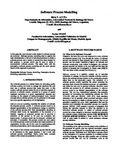
SPEM introduces common concepts and modelling structure to construct models of software development processes [34]. SPEM1.1 uses some basic modelling concepts from UML1.4 to describe rules, constraints, vocabulary, and notation to be used in defining process models [38]. Thus SPEM1.1 meta-model is defined as an extension of a subset of UML1.4, expressed in the SPEM_Foundation package. The SPEM_Extensions package which extends the SPEM_Foundation package, adds the constructs and semantics required for software process engineering. It owns five packages; each package addresses a specific concern of the software process definition. The building block of the SPEM metamodel is the Process Structure package (figure 1). It defines the main structural elements from which a process description may be constructed. In the following, we compare them with primary process model elements. 3.2
Comparison of SPEM1.1 with Primary Process Model Elements
• Activity: In SPEM1.1, an Activity is the main subclass of WorkDefinition. It describes a piece of work performed by one ProcessRole and may consist of atomic elements called Steps. • Product: A WorkProduct in SPEM is anything produced, consumed, or modified by a process. ModelElement (from Core)
Parameter
Classifier
(from Core)
WorkProductKind
(from Core)
+kind 1
ActivityParameter hasWorkPerArtifact : Boolean
0..* WorkProduct isDeliverable : Boolean / kind : WorkProductKind / responsibleRole : ProcessRole
Operation (from Core)
0..*
WorkDefinition +work +subWork / performer : ProcessPerformer / parentWork : WorkDefinition 0..* 0..* {ordered} 0..* +parentWork
+workProduct
ProcessPerformer +performer / work : WorkDefinition 1 ActionState (from Acti vi tyGraphs)
0..1
1 0..* Activity / assistant : ProcessRole +step / step : Step +activity
ProcessRole
Step
+responsibleRole
+assistant 0..*
+activity 0..*
Figure 1. The process Structure package, the core of SPEM1.1 metamodel for process definitions.
22
Reda Bendraou, Marie-Pierre Gervais, and Xavier Blanc
It describes one class of artifacts produced in a process and has a WorkProductKind that describes a category of artifact, such as Text Document, UML Model, Executable, Code Library, and so on. • Role: in SPEM, a ProcessRole is a subclass of ProcessPerformer and defines responsibilities and roles over specific WorkProducts and Activities. Whether SPEM1.1 defines the notion of ProcessRole (Role), it does not provide the one of Human who can undertake this Role. Moreover, concepts equivalent to Tool and Evolution Support are not provided by the standard. In SPEM1.1, software processes are described in static models and there is no support for their evolution during execution-time. Table 1 summarizes correspondences between primary process model elements and those offered by SPEM1.1. It shows that Human, Tool and Evolution Support notions are lacking in SPEM1.1. Basic process model elements Activity Product Role Human Tool Evolution
SPEM1.1 WorkDefintion /Activity WorkProduct ProcessRole -
Table 1. Comparison between primary process elements and SPEM1.1 elements.
3.3
Evaluation of SPEM1.1 Towards Basic PMLs Requirements
In this section, SPEM1.1 is evaluated with respect to requirements on process modelling languages. • Formality: As SPEM1.1 extends a sub set of UML1.4, discussing the formality i.e., syntax and semantics of SPEM1.1 partly comes to discuss the formality of UML 1.4 which is a very large debate. The UML semantics is described using a metamodel that is presented in terms of three views: the abstract syntax, well-formedness rules, and modelling element semantics. The abstract syntax is expressed using a subset of UML static modelling notations and well-formedness rules are expressed in the Object Constraint Language (OCL). The semantics of modelling elements are described in natural language, which may not be sufficiently precise. This may cause disagreements, multiple interpretations and confusion over the precise meaning of a construct [9]. In SPEM1.1, an example of this lack of semantic is the semantic given to the Step element: "An Activity may consist of atomic elements called: Steps" [34]. This is the only reference to Step in the specification, which is obviously insufficient. A Step inherits from UML1.4 ActionState. "An action state represents the execution of an atomic action, typically the invocation of an operation" [38]. But, UML1.4 does not explicitly specify, neither parameters of the invocation action (i.e., name and value) nor their types as it is done with Actions in UML2.0. Then, mapping this element to an executable or analyzable format would be impossible and useless. Let's also consider the concept of ProcessPerformer. The standard defines the
UML4SPM: A UML2.0-Based Metamodel for Software Process Modelling
23
ProcessPerformer as a performer for a set of WorkDefinitions. It also states that ProcessPerformer represents abstractly the “whole process” or one of its components. Definitively, we can clearly note that this definition is confusing. One obvious question would be: what is the practical use of a ProcessPerformer? Is it used as a container for WorkDefinitions or as a role, responsible for specific activities? In the latter case, what is the difference with the ProcessRole concept? We believe that a container of WorkDefinitions and roles are totally two separate concepts that should be expressed separately. • Understandability: SPEM1.1 uses UML notation. This is considered as an advantage as UML has attractive features: it is standard, graphical, intuitive, and easy to be understood. Besides, a wide community of software developers is familiar with UML and uses a UML case tool environment. UML being so popular and widely used, SPEM has an important competitive advantage compared to any specialized PML [8]. • Expressiveness: In this point, we address expressiveness of SPEM1.1 concepts to model software processes and not UML1.4 expressiveness. We have seen in section 3.2., that SPEM1.1 doesn't provide concepts like Human, Tool or Evolution support. In the following, we present other limitations related to the expressiveness criterion: a) In SPEM1.1, a WorkProduct inherits from the UML1.4 Classifier and is used as a parameter into or from Activities (WorkDefinition in general). Nevertheless, we can’t know which Steps of the Activity are going to act on WorkProducts nor responsible roles of these Steps. We think that it would be useful to affect WorkProducts to Steps rather than to Activities for more exhaustive process automation. Also, we believe that we have to provide designers with the possibility to specify and to personalize their own WorkProducts in order to be domain or method specific. The WorkProduct class has some fixed properties such as name, isDeliverable, or kind and it is not possible to add more properties for the WorkProduct. Indeed, with the appearance of the MDA, some specific WorkProducts emerge. Examples are models, model transformation rules and so on. These WorkProducts have different properties each, which can't be resumed by a name and a boolean that indicates either it is a deliverable or not as it is in SPEM1.1. b) During software development process, depending on some results, developers would need to interact and to impose choices about activities to be executed. Human interactions are lacking by SPEM1.1. c) Finally, project managers would also like to have some additional features on process definitions in order to monitor and to capture process metrics during execution-time. Examples of these features could be duration time of an activity, its priority and its thrown exceptions. The current specification does not provide any of those facilities. • Abstraction: As the OMG has chosen an OO approach for modelling software processes [34], SPEM1.1. provides Abstraction thanks to the Generalization/ Specialization mechanism. Indeed, a process model defined by SPEM1.1 can be customized using the inheritance i.e., specialization mechanism in order to fit specific domains or user's requirements. Thus, in the specialized process model, we can add new attributes to new classes that inherit basic ones as well as new references. This
24
Reda Bendraou, Marie-Pierre Gervais, and Xavier Blanc
allows taking advantage of existing process models while adapting them to an appropriate domain. • Modularization: One of the major lacks of SPEM1.1 is ProcessComponent compositions. A ProcessComponent is a chunk of process description that is internally consistent and may be reused with other ProcessComponents to assemble a complete process. However, developers who want to combine two or more ProcessComponents in order to get one coherent process, have to carry out a unification procedure. Indeed, to combine for instance two ProcessComponents P1 and P2, at least the output WorkProducts from P1 must be unified i.e., made identical with the inputs to P2. Other elements may possibly be unified in addition, such as ProcessRoles. Composition of ProcessComponents can be fully automated only if they originate from a common family so that the unification is obviously capable of being automated. Otherwise, the unification would involve human intervention that normally would consist of some re-writing of the elements, and possibly associated elements, to be unified. This could be manageable in case of the combination of two simple ProcessComponents. However in case of complex ProcessComponents, it becomes increasingly difficult. When outsourcing and offshore appear as a new way working for companies, it is important to address this lack. • Executability: Nowadays, companies are looking for how to extensively automate all parts participating in software production, among them the development process itself. However, SPEM1.1 provides as actions of a development activity, the concept of Step, which only represents the name of the action that developer has to perform (e.g., Step x: Check model consistency). This could help for process description but it is so far of its execution. We agree that execution of process models is outside the scope of SPEM1.1. However, we hardly believe that it should provide concepts that enable the specification of executable action semantics within process models. UML2.0 offers this possibility thanks to the Actions packages. It gives precise execution semantics to actions, by defining their effect as well as their typed inputs and outputs. This may help in mapping them into executable actions in some well-known OO languages such as Java or C++ [8]. • Analyzability: SPEM1.1 is defined as a MOF metamodel, based on a subset of UML. This is considered as an advantage as MOF definitions are machine processable. Specifically, the MOF standard dictates how MOF models and instances of MOF models may be rendered in XML format (schemas and XML documents, respectively), and how interfaces to repositories for models can be derived from MOF definitions of the languages in which those models are expressed [20] [19]. This helps in manipulating SPEM1.1 models i.e., creation, suppression or modification, in checking their conformance to the SPEM1.1 metamodel and in analyzing them from different process perspectives (e.g. to get ProcessRole for the Activity: x, or Steps owned by the Activity: y, how many WorkProducts are used by the WorkDefinition: z, and so on). • Reflection: Reflection is about whether SPEM1.1 supports process models evolution (static or dynamic) or not. In fact, SPEM1.1 doesn't provide mechanisms for dynamic evolution of process models. Static evolution is offered by manipulating process models outside execution-time. • Multiple conceptual perspectives/views: Another considerable advantage for SPEM is that is defined both as a metamodel and as a UML profile, which allows
UML4SPM: A UML2.0-Based Metamodel for Software Process Modelling
25
SPEM modelers to use the UML as a concrete notation. Thus, SPEM both defines modelling capacities dedicated to the software process domain, and gains the benefit of the expressiveness of UML. For example, Use Case modelling, which is sometimes used for modelling processes, is not defined as a specific SPEM facility, but can be inherited from UML. Other UML diagrams i.e., Class, Package, Sequence, State chart and Activity diagrams can be used by SPEM1.1 with some restrictions. For instance, SPEM1.1 allows the use of UML Sequence diagrams to illustrate interaction patterns among SPEM model element instances with the restriction that only stick arrowheads should be used [34]. Table 2 summarizes the result of the evaluation of SPEM1.1 with respect to basic PML requirements. Basic PML Requirements
SPEM1.1
Formality
-Lacks of a precise semantic of some elements (Step, ProcessPerformer…).
Expressiveness
-Lacks of some process model elements (Human, Tool and Evolution Support); -WorkProducts are used as parameters of Activities and not of Steps(useless for process automation) -Impossibility of defining explicit WorkProducts properties; -Lacks of human interactions and decision points; -Lacks of some features on process elements in order to capture process metrics, exceptions.
Understandability Abstraction Modularization Executability Analyzability
Reflection
-Good. Uses UML as a notation -Good. As an OO PML, SPEM1.1 offers Generalization/Specialization mechanism to deal with Abstraction. -Lacks of ProcessComponent compositions. Need of a Unification mechanism. -Major Lack. SPEM1.1 models are not executable. It was outside the scope of the specification. -Good. Possibility to manipulate process models and to analyze them thanks to MOF repositories. -Lack
Multiple conceptual -Good. Thanks to the possibility of using UML diagrams as SPEM1.1 is a UML profile. perspectives/views
Table 2. Evaluation of SPEM1.1 with respect to basic requirements of PMLs. As we can notice, SPEM1.1 suffers from several lacks at different levels of PML requirements. Principal ones are: Formality, Expressiveness, Modularization, Executability and Reflection, whereas it has serious advantages in Understandability, Abstraction, Analyzability and Multiple conceptual perspectives/views. In the next section we introduce our solution and show how it overcomes these lacks.
26
4
Reda Bendraou, Marie-Pierre Gervais, and Xavier Blanc
UML4SPM: A UML2.0-Based Metamodel for Software Process Modelling
As intent to overcome SPEM1.1 limitations, our proposition for modelling software processes comes in form of a MOF-compliant metamodel named: UML4SPM. It takes advantages of the expressiveness of UML2.0 by extending a subset of its elements suitable for process modelling. By adopting UML2.0 as a basis of our metamodel, we will take advantage of: o The expressiveness of the new UML2.0 for modelling executable action semantics within activities and in orchestring them; o The fact that UML is currently the most widely used modeling language in the industry; o Tool supports and facilities; o Notations and diagrams offered by the standard ; o Easier adoption by UML and SPEM1.1modelers; 4.1
Metamodel Presentation
As in SPEM1.1, UML4SPM comes in form of package hierarchies. The outermost level contains two packages: the SPEM_Foundation package and the SPEM_Extensions package (see figure 2). The SPEM_Foundation package contains all UML2.0 packages required as a basis for defining software process models. Main ones relate to Activities, Actions, Behavior and Kernel packages. The SPEM_Extensions package holds packages that extend UML2.0 and add the constructs and semantics required for software process modelling i.e., the ProcessStructure package and the WorkProducts package. Figure 3 point out how concepts of both packages are interconnected. It gives a global overview of UML4SPM Lighted boxes of the figure represent UML2.0 classes. Shaded boxes represent those we specified and that inherit UML2.0 classes. We start the description of the metamodel by SPEM_Extensions packages. Process Structure Package The ProcessStructure package is the core of UML4SPM. Its main class is the Process class (figure 3). A Process inherits form UML2.0 BehavioredClassifier. A BehavioredClassifier is a Classifier that has Behavior specifications defined in its namespace. One of these may specify the classifier's behavior itself which will be invoked when an instance of the BehavioredClassifier is created. One advantage is that the Process's behavior can be represented by state machines; this adds more control on the Process lifecycle. Another advantage, being a Classifier, a Process can be categorized and can own (encapsulate) other Classifiers such as WorkProducts as well as ActivityPerformer on these WorkProducts. A Process has a name and is governed by a Lifecycle. It is composed of SoftwareActivities, which extends the UML2.0 Activity. A Process may be defined by a meta-process thanks to the metaProcAssoc association. A SoftwareActivity may be an Activity or a Phase depending on the value of the Kind attribute.
UML4SPM: A UML2.0-Based Metamodel for Software Process Modelling
27
SPEM_Foundation Kernel BasicBehaviors
BasicActions
FundamentalActivities
IntermediateActions
BasicActivities
StructuredActivities
CompleteActions
ExtraStructuredA ctivities
IntermediateActivities
CompleteStructuredActivities
Communications
CompleteActivities
SPEM_Extensions
ProcessStructure
WorkProducts
Figure 2. UML4SPM Package hierarchies As mentioned previously, we need to have some features within activity descriptions that help in monitoring and in getting metrics on development processes. Thus, we define a new property named weigh within SoftwareActivity. It represents its importance in the development process (e.g. collecting user's requirements = 30%) and a TimeLimit class linked to the SoftwareActivity class with the starts at, ends at associations and witch represents time estimations defined by the team. Based on these metrics, project managers may affect more time and resources to Activities having a high weight. A SoftwareActivity contains Actions. An Action takes a set of inputs and converts them into a set of outputs, though either or both sets may be empty. Input to, respectively, output from, an Action is a typed element. It represents the Pin of the Action. A Pin is typed by a Classifier. A SoftwareActivity has one or more ActivityPerformer who are in charge of the SoftwareActivity and more particularly of Actions owned by it. An ActivityPerformer can be a ResponsibleRole or a SoftwareTool (i.e. compilers, model transformation engines…). A ResponsibleRole describes the rights and responsibilities of the Human who will be in charge of the Activity. A Human may be an agent or a team; it has a name, a skill(s) and an
28
Reda Bendraou, Marie-Pierre Gervais, and Xavier Blanc Classifier (from Kernel)
+context {subsets ownedMember} +ownedBehavior Behavior * 0..1 (f rom BasicBehav iors) +classifierBehavior 0..1 {subsets ownedBehavior} 0..1
BehavioredClassifier (from BasicBehaviors)
+defineProcess 1
Process
metaProcAssoc
1
1
+gouvernedLifecycle
Lifecycle / governed... LifecycleKind : String
0..1
ActivityPerformer
0..* {filters owner} 0..1 +activity
ResponsibleRole responsability : String ownedElement} +node{filters Rights : String * +Role ActivityNode 1..* 1 (from IntermediateActivities)
SoftwareActivity Kind : SoftwareActivityKind weight : String
+involves
0..1
+endsAt +startAt 0..1 0..1 TimeLimit
SoftwareActivityKind
+agent 0..* {ordered filters node} Human name : String authority : String skill : String
+action 0..*
{filters owner} Action +action effect : String 1
Phase : String Activity : String
0..*
{filters input} * +inputPin
1
1
TypedElement (from Kernel)
+impacts 0..n WorkProduct
+workProduct 0..*
(from WorkProducts)
isDeliverable : Boolean resourceIdentifier : String
0..n +property
Property propertyName : String value : String
(f rom BasicActions)
Classifier
SoftwareTool name : String isBatch : Boolean = true
+action {filters owner} {ordered, union subsets ownedElement} +output * OutputPin
InputPin (f rom BasicActions)
(from Kernel) +type
+ActivityPerformer
(f rom IntermediateActiv ities)
1 +processActivity {ordered} 0..n
+metaprocess
+performer +activity
Activity
Pin (from BasicActions)
Interaction
Figure 3. A global overview of UML4SPM
authority. Actions consume and produce WorkProducts. The relation between an Action and WorkProducts it handles is made through the fact that WorkProducts are Classifiers and Inputs and Outputs of an Action have a type which is specified by a Classifier too. This would allow Actions to manipulate WorkProducts as easily as calling a method while passing it parameters in usual OO programming languages. WorkProducts Package A WorkProduct is the specification of a physical piece of information that is produced, consumed, or modified by a software process. In UML4SPM, we decide to add a new property to the WorkProduct class, the resourceIdentifier property (figure 4). It represents a unique identifier of the WorkProduct and helps in its localization. Then, during process executions, it should be up to a naming service to resolve the identifier in order to locate the WorkProduct. WorkProduct is specified as a concrete class. It may have Properties defined by a name and a value. This adds more flexibility (see figure 4). Thus, developers could specify new WorkProducts with specific properties depending on their needs. The modification of a WorkProduct may affect one or more WorkProducts. This property is defined thanks to the impacts association.
UML4SPM: A UML2.0-Based Metamodel for Software Process Modelling
29
Classifier (from Kernel)
+impacts 0..n Work Product isDeliverable : Boolean localisationUri : String
+property 0..n Property propertyName : String value : String
Figure 4. The WorkProducts package Additional Actions As pointed out earlier, a software development process can’t be fully automated. Developer involvements are necessary during development phases. Considering this need of human interactions, we add the concept of Interaction. An Interaction is an Action. It involves a ResponsibleRole and is associated with a Guide in order to help ResponsibleRole in taking decisions and guides its design choices (see above figure 3). Finally, having in mind that processes may need some tool facilities during execution-time, we decide to extend the Actions model. The CallToolServiceAction is a CallAction (see figure 5). It has InputPins which represent the arguments of the call and OutputPins as call results. We make the assumption that a ToolService has a name and a set of typed parameters. One constrain on the CallToolServiceAction, would be that CallToolServiceAction arguments fits to ToolService parameters (in number and type). The model of the tool (list of services, parameters of services, binding mode…) is outside the scope of this work [3].
InvocationAction
{ordered, subsets input} +argument ValueSpecification *
OutputPin
(from Kernel)
CallAction
*
(from BasicActivities)
+result {ordered, subsets output}
CallToolServiceAction
isSynchronous : Boolean = false
ToolService
name : String
Figure 5. The CallToolServiceAction 4.2
Comparison of UML4SPM with Respect to Basic Process Model Elements
Table 3 compares UML4SPM elements with basic process model elements introduced in Section 2. The concept of Tool (SoftwareTool) which will be in charge of
30
Reda Bendraou, Marie-Pierre Gervais, and Xavier Blanc
performing activities as well as Human that may undertake roles within the software process can now be expressed in process models. Basic Process model Elements Activity Product Role Human Tool Evolution support
UML4SPM SoftwareActivity with Kind attribute= Activity WorkProduct (Model/Guide/Library/Documentation) ResponsibleRole Human SoftwareTool Only static evolution. Dynamic evolution as further work
Table 3. Comparison of primary process elements with UML4SPM 4.3
Evaluation of UML4SPM Towards Primary PMLs Requirements
In this section, we only address requirements that were lacking by SPEM1.1. As a first stage, we particularly focus on Expressiveness, Modularization, Executability and Formality. Reflection will be addressed in a further work. Requirements for Understandability, Abstraction, Analyzability and Multiple conceptual perspectives/views are taking into account since UML4SPM, as SPEM1.1, is UML based (cf. Section 3.3). • Expressiveness: In SPEM1.1 the ability to orchestrate process Activities and Steps was ensured thanks to the Precedes dependency. Kinds of precedence were: start-start, finish-start or finish-finish. UML2.0 Activities offer three mechanisms for the orchestration of Activities as well as Actions owned by these Activities: - The CallBehaviorAction overcomes Activity orchestration limitations. It is a callAction that invokes a behavior directly rather than invoking a behavioral feature that, in turn, results in the invocation of that behavior. Activity being a Behavior, therefore, an Activity could be invocated while passing typed parameters to be treated by Actions owned by the Activity. This adds more flexibility for Activity orchestrations (figure 6). - Object flow connects object nodes. It expresses the fact that the output of an action could be used like an input of another one. - Control flow: In the absence of an explicit object flow between actions, a control flow indicates an ordering constraint between a predecessor action and a successor action. It explicitly connects Actions to indicate that the target action cannot start until the source action finishes. - Concerning flexibility, decision points are not taken into account by SPEM1.1. UML2.0 offers the possibility to specify decision points thanks to DecisionNodes. A Decision Node is a Control Node that chooses between outgoing flows in order to invoke the appropriate behavior. Guards are fixed on those flows to drive behavior invocations. In order to express concurrency as well as synchronization, UML2.0 defines respectively, ForkNode and JoinNode. A ForkNode splits a flow into multiple concurrent flows while a JoinNode synchronizes them.
UML4SPM: A UML2.0-Based Metamodel for Software Process Modelling
31
Action (fromBasicActivities)
Invocati onActi on
CallActi on
{ordered, +resul t subsets output} * OutputPi n (from BasicActivities)
CallOperationAction
isSynchronous : Bool ean = true
*
CallBehavi orAction
0..1
isSynchronous : Bool ean = true *
+behavior Behavior
1
+operati on
(from BasicBehaviors)
Activity (from BasicBehaviors)
{ordered, subsets input}
1
Operati on (from Kernel)
+target {subsets i nput} +argument 1 * ValueSpecification (fromKernel)
Figure 6. The CallBehaviorAction for Activity orchestrations - The UML2.0 Activity metamodel defines seven levels with increasing expressiveness: FundamentalActivities, BasicActivities, IntermediateActivities, CompleteActivities, StructuredActivities, CompleteStructured-Activities, and ExtraStructuredActivities. The fundamental level defines activities as containing nodes, which includes actions. The second level i.e. IntermediateActivities provides the way to specify concurrency and synchronization through ControlNodes (ForkNode, JoinNode). This would allow activities to be launched concurrently or for an activity before starting, to wait for other activity completions. The StructuredActivities level supports modelling of traditional structured programming constructs, such as loops and conditionals, as an addition to the basic non-structured activity sequencing. - In UML2.0 Activity metamodel, another facility is offered to process modelers. It is about how to support exception handling during Action executions. This is ensured within the (“ExtraStructuredActivities”) level. As in programming languages, an Action can be handled by exception handlers. - Finally, the lack of some process model elements (tool, human), of human interaction, of explicit WorkProduct and features for process metrics was addressed while defining UML4SPM (see Section 4.1). • Modularization: When SPEM1.1 offers process component compositions through unification procedure, UML2.0 provides a more powerful way to deal with that. Let’s have two Process Components PC1 and PC2 (see figure 7). PC1 is in charge to realize a UML class diagram. PC2 has to transform a UML Class Diagram to a Relational Database Diagram. These two processes were specified separately, so WorkProducts and roles might have different names. If a process modeler decides to
32
Reda Bendraou, Marie-Pierre Gervais, and Xavier Blanc
compose these two process components, he will have to unify output-WorkProducts from PC1(i.e., ClassD) in order to be in conformity with inputs-WorkProducts of PC2(i.e., UmlCD). Likewise, he has to explicitly link activities from PC2 within PC1. Because of these limitations, unification procedure can’t be automated. ClassDiagramPC : ProcessComponent
ownedElement ownedElement designer : ProcessRole
ownedElement
Note: [Output parameter]
assistant parameter
Class Diagram Elaboration : Activity
ClassDiag : ActivityParameter
step
type
identify Objects : step Step
Model : WorkProduct
step
identify class objects : Step
.... : Step
PC1: Class Diagram Process Component UML Model : WorkProduct type UmlCD : ActivityParameter parameter Class Diagram To RDB transformation : Activity Note: [input parameter]
step
step step
assistant load Src & Tgt Metamodels : Step
load model : Step ownedElement Transformation designer : ProcessRole ownedElement
.... : Step
ownedElement cdTOrdbPC : ProcessComponent
PC2: Class DiagramToRDBTransformation Process Component
Figure 7. Two SPEM1.1 process components Considering that a UML2.0 Activity can define an internally consistent process, Activities can be seen as a Process Components. The UML2.0 CallBehaviorAction allows to Activities to be interconnected in a practical way. The advantage of this construct is that Activity behaviors are invoked as it is done for methods in classical programming languages. Making this way, modelers don’t have to carry out the unification of PC1 outputs with PC2 inputs. In Java for instance, parameters of a method call can have another name in the operation signature. CallBehaviorAction being a CallAction, casting of parameters is done implicitly when activities are
UML4SPM: A UML2.0-Based Metamodel for Software Process Modelling
33
invoked thanks to the abstraction given by InputPins and OutputPins concepts. The previous example is used in order to demonstrate how CallBehaviorAction allows process component compositions see figure 8.Shaded boxes of the figure represent the “class diagram realization” Activity. In the figure we can see how output of an Action (i.e., a ClassDiagram) can be used as an input of CallBehaviorAction. The lighted boxes of the figure represent “ClassDiagram-ToRDBTransformation” Activity. The two activities are interconnected thanks to ActivityParameterNode and no unification procedure is needed. Then, process component compositions (Activities composition in this case) can be automated. They can even be specified at execution-time. This offers more flexibility and spares many efforts to process modelers. ClassDiagramElaboration : Activity
action action
ntify Objects : Action
action identify object classes : Action
ClassDiagram : OutputPin
output
type
: Parameter
.... : Action
CallModelTransformationActivity : CallBehaviorAction
CD : Model
type
action
type
behavior CD_UML : InputPin ClassDiagramToRDBTra nsformation : Activity
parameter
node
: ActivityParameterNode action action action
Load SRC & TRG metamodels : Action
Load source Model : Action .. : Action
Figure 8. Activity interconnections thanks to CallBehaviorAction. • Executability: In UML2.0, the intent of Activity construct has changed fairly radically from UML1.x. Activities are not only used to model processes, they also now have some features necessary to support the automation of these processes [36]. Comparing the UML2.0 Activity and Action constructs with those of SPEM1.1 WorkDefinition (more particularly the Activity) and Step respectively, we found some significant variations. While an activity Step in SPEM1.1 is just defined by a name (e.g. Check for model consistency), UML2.0 offers the possibility to specify inputs of the Action, its effect on these inputs and the outputs resulting of the action execution. We illustrate this in an example in figure 9. CallOperationAction is an Action that transmits an operation call request to the target object, where it may cause the invocation of associated behavior. As additional features, CallOperationAction
34
Reda Bendraou, Marie-Pierre Gervais, and Xavier Blanc
specifies the operation to be invoked by the action execution as well as the target object to which the request is sent. Besides, UML2.0 offers four Actions packages (BasicActions, IntermediateActions, Structured Actions and CompleteActions) in order to express most semantic of executable actions that we can find in programming languages (CallAction, LinkAction, CreateObjectAction, StructuralFeatureAction, ValueSepcification-Action and so on). Thus, the specification of software process models with executable action semantics is rendered possible. By the same way, the rigorous semantics given to Actions within the new UML2.0 standard tends to be more precise than previous versions of UML. Indeed, the Activity and Action constructs in UML2.0 are more sophisticated than Activity and Step in SPEM1.1 This facility makes possible the automation of mapping software process models towards programming languages or workflow formalisms in order to execute them. Some works was already done as intent to formalize Activities within UML2.0 [13] [36]. Furthermore, the OMG issues a new RFP (Request For Proposal) named: Executable UML Foundation [33]. The objective of this RFP is the definition of a computationally complete and compact subset of UML 2.0 to be known as “Executable UML Foundation”, along with a full specification of the execution semantics of this subset. “Computationally complete” means that the subset shall be sufficiently expressive to allow definition of models that can be executed on a computer either through interpretation or as equivalent computer programs generated from the models through some kind of automated transfor-mations. We believe that all these efforts will reduce the lack of Formality in SPEM1.1. Class Diagram Realization : Activity
composedOf
CallClas sDCons istencyOp : CallOperationAction
input operation
IncClassDiagram : InputPin
output
CheckModelCons istency : Operation
typed
ConsClas sDiagram : OutputPin
typed
UML Clas s Diagram : Model + isUMLCompliant : Boolean = tr... + uriParentModel : String = null
Figure 9. Instance of CallOperationAction Table 4 summarizes the result of comparing UML4SPM with basic PML requirements. As we can notice, our metamodel overcomes major SPEM1.1 lacks requirements of Understan-dability, Abstraction, Analyzability and Multiple conceptual perspectives/views are fulfilled as UML4SPM is UML based.
UML4SPM: A UML2.0-Based Metamodel for Software Process Modelling Basic PML Requirements Formality Expressiveness
SPEM1.1
UML4SPM
-Lacks of a precise semantic of some elements (e.g. Step, ProcessPerformer). -Lacks of some process model elements (Human, Tool and Evolution Support); -Lacks of efficient mechanism for Activity and Step orchestrations; -WorkProducts are used as parameters of Activties and not of Steps(useless for process automation); -Lacks of explicit WorkProducts (models, libraries…);
-Formality provided thanks to the precise and executable semantics of Actions within UML2.0 -SoftwareTool and Human elements provided to overcome this lack -Three mechanisms for Action and Activity orchestrations: Control Flow, Object Flow and the CallBeaviorAction. - WorkProducts are used as typed parameters by Actions; -Definition of explicit WorkProduct (Model, Guide, Library and Documentation); urilLocalization attribute for WorkProducts; WorkProduct as a concrete class with the possibility to specify new properties. - Class Interaction defined for human decisions as well as Decision, Fork and Join Nodes thanks to UML2.0 - TimeLimit, SoftwareActivity weight for process metrics; the possibility to handle exceptions thanks to ExceptionHandler in ExtraStructuredActivities -Process Component composition/integration thanks to the CallBehaviorAction from/to Activities -Use/extends of Activities and Actions packages of UML2.0 makes possible the specification of executable software process models - Will be addressed in a further work.
-Lacks of human interactions and decision points -Lacks of some features on process elements in order to capture process metrics, exceptions;
Modularization Executability Reflection
35
-Lacks of ProcessComponent compositions mechanism. Need of a Unification mechanism. -SPEM1.1 models are not executable. It was outside the scope of the specification. -Lacks
Table 4. Comparison of UML4SPM with PML requirements and with SPEM1.1 lacks
5
Related Work
In this Section, we only deal with existing approaches that extend the UML metamodel for software process modelling. Taxonomy of recent PMLs is given in [39]. In PROMENADE [12], a UML metamodel is extended to allow modeling of both the static and the dynamic aspects of software processes. The static aspect of software processes is given by means of a conceptual model. It defines the elements that participate in a software PMs and which extend UML ones. The dynamic aspect of software processes consists of the way in which model is enacted (e.g. the ordering of tasks). PROMENADE introduced both proactive control-flow (e.g., enactment of some actions according to pre-establish plan) and reactive control-flow (e.g., enactment of some actions in response to events). Authors were induced to introduce these mechanisms in order to deal with the lack of expressiveness in UML1.4 activity diagrams [31]. Nevertheless, PROMENADE does not provide the possibility to specify Tasks with executable semantics. It lacks of evolution support as well as of the Interaction element (i.e., human intervention) which is primordial due to the variability and no-rigidity nature of software processes. [18] Presents an approach which describes in UML, the dynamic part of the model using class diagrams with stereotyped associations for showing the control and data flow. The metamodel is defined by attaching stereotypes to model elements. However, stereotypes and other UML extension mechanisms have proven several
36
Reda Bendraou, Marie-Pierre Gervais, and Xavier Blanc
limitations in order to define a metamodel. A well-known is the lack of standard semantics. As in [18], [22] proposes the use of the stereotype mechanism of UML to extend activity diagrams in the context of business process modelling. The new diagrams can express the required activity properties (computer support to the activity, duration...) but no new control paradigm is provided. In [17], authors select class and state diagrams as main constructs to describe processes. Tasks are represented as objects that can be created and manipulated as needed. Activities (tasks) are represented as "task packages" which encapsulate the interface of a task (i.e., offered behavior) and "realization packages" which define how the task is realized in terms of other lower level tasks. In the corresponding class diagrams, stereotypes are used to represent the input and output of each task, as well as the flow of control and data between tasks which is missing in UML1.4 activity diagrams. The internal behavior of tasks is described by a predetermined and un-modifiable state diagram. Compared to previous approaches, this one is clearly more focused on adapting UML to the capabilities and semantics of the virtual machine that will be used to enact the process. Therefore, the process is described at a low level of abstraction. However, it is not apparent how roles that participate in the process are described and how they are associated to the various activities to be executed, or how possible parallelisms between activities, synchronizations and decision points are expressed. This, together with the replacement of activity diagrams with massively stereotyped class diagrams makes the resulting process description less natural for UML users. In [8] Di Nitto et at., propose a formalization of the semantics of the UML subset and present the translation of UML process models into code, which can be enacted in a process-centered environment. However, as in PROMENADE, authors did not consider modeling the interface with human agents and/or the development tools used in the process. Likewise, no semantics for executable actions is defined in PM
6
Conclusion
One important challenge in the area of software process modelling is the development of a standard PML. As principal requirements, the PML has to promote expressiveness, understandability, and executability. In this paper, we introduced a UML2.0-based metamodel for software process modelling named: UML4SPM. It extends a subset of UML2.0 by adding constructs and semantics required for defining process models. We compared it with primary PMLs requirements. UML4SPM has proven that it fulfils all of them except Reflection, which will be addressed in a further work. As a result, it allows the specification of understandable process models with executable action semantics. Another contribution of this work was the identification of SPEM1.1 limitations and advantages which may help in the next revision of the standard, namely: SPEM2.0. One perspectives of this work is to address the Reflection requirement in UML4SPM. Then, a case study will be elaborated and evaluated within the MODELWARE project [25], which this work is part of. We will also investigate the possible use of a UML virtual machine in order to execute UML4SPM process models.
UML4SPM: A UML2.0-Based Metamodel for Software Process Modelling
7
37
References
[1] Ambriola V., Conradi R. and Fuggetta A. “Experiences and Issues in Building and Using Process centered Software Engineering Environments”, Internal draft paper, Politecnico di Milano, September 1994. [2] ANSI/IEEE Std 1012-1986, "IEEE Standard for Software Verification and Validation Plans", The Institute of Electrical and Electronics Engineers, Inc., February 10, 1987. [3] Blanc X., Gervais M.P., and Sriplakich P. "Model Bus: Towards the Interoperability of Modelling Tools", in Proc. of the Model Driven Architecture: Foundations and Applications (MDAFA 2004), Linköping University, Sweden, June 2004. [4] Conradi R., Fernström C., Fuggetta A. and Snowdon R. "Towards a Reference Framework for Process Concepts", in Proc. Of the 2nd European Workshop on Software Process Technology (EWSPT’92), Trondheim, Norway, September 1992, LNCS Vol. 635. [5] Conradi R., Liu C. "Process Modelling Languages: One or Many?", in Proc. of the 4th European Workshop on Software Process Technology (EWSPT'95), Noordwijkerhout, The Netherlands, April 1995, LNCS, Vol. 913. [6] Curtis B., Kellner M., and Over J. "Process Modelling", Communications of the ACM Vol. 35, Num. 9, September 1992. [7] Derniame J.C., Kaba B.A. and Wastell D. "Process Modelling Languages": in "Software Process: Principles, Methodology, and Technology", LNCS Vol. 1500/1999. [8] Di Nitto E. et at. "Deriving executable process descriptions from UML", in Proc. of the 24th Inter. Conf. on Software Engineering (ICSE'02), Orlando, Florida 2002, ACM Press. [9] Evans A.S., S.Kent. "Meta-modelling semantics of UML: the pUML approach", in Proc. of the 2nd Inter. Conf. on the Unified Modelling Language, 1999, Colorado, LNCS Vol. 1723. [10] Feiler P.H., Humphrey Watts. S. “Software process development and enactment”, in Proc. of 2nd Inter. Conf. on the Software Process, Berlin, 1993, IEEE Computer Society Press. [11] FIPS PUB 132, "Guideline for Software Verification and Validation Plans", U.S. Department of Commerce/National Bureau of Standards (U.S.), November 19, 1987. [12] Franch X., Ribó J. M. "Using UML for Modelling the Static Part of a Software Process", in Proc. of UML ’99, Forth Collins CO, USA, LNCS, Vol.1723. [13] Hausmann J.H., Störrle H., "Towards a Formal Semantics of UML 2.0 Activities", in Proc. of the German Software Engineering Conference (SE'05). [14] Humphrey Watts S. "Process Models in Software Engineering", Encyclopedia of Software Engineering, 2nd Edition, John Wiley and Sons, Inc, New York, December 2001. [15] Humphrey Watts S. "The Software Engineering Process: Definition and Scope", in Proc. of the 4th International Software Process Workshop on Representing and Enacting the Software Process, Devon, United Kingdom, 1989. [16] Jaccheri M.L., Baldi M., Divitini M., "Evaluating the Requirements for Software Process Modelling Languages and Systems", in Proc. of Process support for Distributed Team-based Software Development (PDTSD'99), Orlando, Florida, USA, August 1999. [17] Jager D., Schleicher A., and Westfechtel B. "Using UML for Software Process Modelling", in Proc. of ESEC/FSE'99,Toulouse, France, LNCS Vol.1687, September 1999. [18] Jäger D., Schleicher A., Westfechtel B." Object-Oriented Software Process Modeling", in the Proc. of the 7th European Software Engineering Conference (ESEC), Toulouse, September 1999. [19] JMI1.0, "Java Metadata Interface Specification", Java Community process document JSR040, June 2002, at http://www.jcp.org. [20] Kent S. "Model Driven Engineering", in Proc. of the 3rd Inter. Conf. on Formal Method (IFM 2002), Turku, Finland, May 2002, LNCS Vol. 2335.
38
Reda Bendraou, Marie-Pierre Gervais, and Xavier Blanc
[21] Lonchamp J. “A structured conceptual and terminological framework for software process engineering”, in Proc. of the 2nd Inter.l Conf. on Software Process, Berlin, 1993, IEEE Computer Society Press. [22] McLeod, G. "Extending UML for Entreprise and Business Process Modeling", in Proc. of the UML 98’ Workshop, Mulhouse, France (1998). [23] MDA. "Model Driven Architecture (MDA)", OMG TC document ormsc/2001-07-01, July 2001, at http://www.omg.org. [24] Mellor S. J., Balcer M. J., Balcer M. "Executable UML: A Foundation for Model-Driven Architecture", Pearson Education, July 2002. [25] MODELWARE Project, at http://www.modelware-ist.org [26] MOF 1.4. "Meta-Object Facility", OMG document formal/2002-04-03, April 2002, at http://www.omg.org. [27] Montangero C., Derniame J.C., and Kaba B.A., Warboys B. "The software process: Modelling and technology", LNCS GmbH. Vol. 1500/1999. [28] Osterweil L., "Software Processes Are Software Too" in Proc. of the 9th Inter. Conf. on Software Engineering (ICSE'9), New York, 1987, ACM Press. [29] Perry D. E., Editor, Proc. of the 5th Inter. Software Process Workshop (ISPW’5), Kennebunkport, Maine, USA, October 1989, IEEE Computer Society Press. [30] Raistrick C., Francis P. and Wright J. "Model Driven Architecture With Executable UML", Cambridge University Press, March 2004. [31] Ribó J. M., Franch X. " A Precedence-based Approach for Proactive Control in Software Process Modelling", in Proc. of the Conf. on Software Engineering and Knowledge Engineering (SEKE-2002), Ischia (Italy), ACM Press, September 2002. [32] Riehle D., et at. "The Architecture of a UML Virtual Machine", n Proc. of the 2001 Conf. on Object-Oriented Programming Systems, Languages, and Applications (OOPSLA '01), ACM Press, 2001. [33] Semantics of a Foundational Subset for Executable UML Models RFP, OMG document ad/05-04-02, April 2005, at: http://www.omg.org/docs/ad/05-04-02.pdf, page last visit June 17, 2005 [34] SPEM1.1, “Software Process Engineering Metamodel”, OMG document formal/02-11/14, November 2002, at http://www.omg.org. [35] SPEM2.0 RFP, “Software Process Engineering Metamodel”, OMG document ad/200411-04, November 2004, at http://www.omg.org/docs/ad/04-11-04.pdf, page last visit April 4, 2005. [36] Störrle H. "Semantics of UML2.0 Activities with Data-Flow", in Proc. of the Visual Languages and Formal Methods Workshop (VLFM'04), Rome, Italy, Septembre 2004. [37] UML2.0 Superstructure, "Unified Modelling Language", adopted specification, OMG document ptc/04-10-02, October 2004, at http://www.omg.org. [38] UML1.4, "Unified Modelling Language", OMG document formal/01-09-67, September 2001, at http://www.omg.org. [39] Zameli, K. Z., Lee, P.A. "Taxonomy of Process Modelling Languages", in Proc. of the ACS/IEEE Inter. Conf. on Computer Systems and Applications (AICCSA'01) Beirut, Lebanon, June 2001.