IJCSNS International Journal of Computer Science and Network Security, VOL.7 No.8, August 2007
273
Software Process Modelling using Attribute Grammar Rodziah Atan, Abdul Azim Abd. Ghani, Mohd Hasan Selamat, & Ramlan Mahmod , University Putra Malaysia, Serdang, Selangor Darul Ehsan, Malaysia
Summary The creations of models are essential for many knowledge disciplines to explain expected results. Modelling concept is well accepted in software engineering discipline. However, there is still a lacking integration of software process modelling and software process measurement by software engineers. This paper aims to portray the idea and result of integrating measurement in software process modelling. The objective of the integration is to show that measurement in modelling software processes is important whereby to reduce reworks in large software development. This research focused on IDEF3 Standard notation as its approach to design software process models, IDEF3-SPMA language constructs as its medium for automatic metric calculation and measurement metric defined specifically to fit the research scope. Attribute grammar approach is used to specify the measurement metrics defined. A tool is also developed to realize the whole idea of integration and metric definition, and it is called Software Process Measurement Application.
Key words: Software process modelling, attribute grammar, software metrics.
1. Introduction Developing reliable software within time scheduled and cost estimated is a difficult task for many software development companies. Any flaws or late delivery of a system means a great deal for many individuals involved. It is indeed vital to produce reliable software right on schedule to avoid inconveniences for the developers, vendors and users. The software community places great hope on software modelling notations and techniques to ease this particular software development challenge. Software process modelling (SPM) is one of the techniques used to creatively define and analyse significant aspects, which can be adapted into convoluted application development and can be used to structure a strategic co-ordination for the development team. Owing to the creativity and dedication of researchers in software engineering area, there are many ways to define software processes. SPM nowadays has even reached a level that allows software designs to be transformed into languages, such as architecture design language (ADL) and unified modelling language (UML).
Manuscript received August 5, 2007 Manuscript revised August 20, 2007
They were designed and created in such ways for better understanding and usage of software process modelling techniques. One of such ways is process modelling using language construct [1]. The effort in using and enhancing similar technique continues and virtual reality process modelling language (VRPML) is one of the specifications [2]. The selection of attribute grammar (AG) approach to realize modelling of software processes modelling in language construct is based on its specification and automatic construction of language-based editors. AG also provides a formal, yet intuitive notation for specifying a static semantics of programming languages and has been variously used for constructing compiler generator systems [3]. Integrated Definition for Process Capture (IDEF3) is the basis for Software Process Measurement Application (SPMA - a language-based process model analyzer system) process model design and its language structure. The selection of IDEF3 is mainly to formalize the software process model notation.
2. Modelling Software Process Using IDEF3 Notation IDEF3 is a standard that was designed to formalize the documentation and the analysing activities of an existing, or proposed systems processes [4]. Proven guidelines provided by the method that comes along with a language for information capture, help users to capture and organize process information for multiple downstream uses. Some of the more prominent motivations for using IDEF3 standard are as below: - To enhance the productivity of business system analysis - To facilitate design data life cycle management - To support the project management process - To facilitate the system requirements definition process and - To support coordinated activity and integration of effort Some of basic process descriptions used in business environment are also applied in software environment
274
IJCSNS International Journal of Computer Science and Network Security, VOL.7 No.8, August 2007
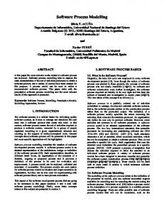
such as data design, system requirement definition, preliminary studies of system requirement and single unit development and system integration. The essence of IDEF3 methodology is its ability to describe activities and their relationship at various levels of detail. An initial model includes parent activities that are decomposed into lower level activities [5]. IDEF3 is divided into two parts of representing the knowledge acquisition of a process, namely processcentred and object-centred strategies. These two categories of IDEF3 are for the flexibility of the users to model their environments in which one approach they know best. IDEF3 is like describing the real world in a form of a model structure. IDEF3 discussed in this paper is categorized as ‘processcentred view’ where it uses process schematics method, which is the primary means for capturing, managing and displaying process centred knowledge. These schematics provide a graphical medium that helps domain experts and analysts from different application areas to communicate knowledge about processes. Knowledge acquisition that normally represented in this view includes knowledge about events and activities, the objects that participate in the occurrences and the constraints that govern the behaviour of an occurrence. Figure 1 below shows an example of process schematic activities depicted in process-centred view.
Fig. 1 Example of IDEF3 process-centred view diagram.
Figure 1 describes that there are six processes that linked together to represent the process flow of an activity of ‘Order Material’. The junction ‘X’ indicates that between processes (2) – Identify potential suppliers and process (3) – Identify current suppliers are complimented (suppliers to be identified can only be in potential list or current list of suppliers, they can not be in both list). The usage of IDEF3 described in this paper is, as process modelling standard for software process measurement
activities. The IDEF3 syntax modelling methodology comes with a language structure of the process design. The language is then enhanced to suit the study problem and was named as IDEF3-SPMA language. Definitions and specifications were given to the enhanced version of IDEF3 language to collect measurements of software process model designs.
3. SPMA Measurement Attributes Software metrics is a collective term used to describe a very wide range of activities concerned with measurement in software engineering. One of the most ‘in use’ metric is information collection metric for source code properties characterization, which is the original or the classic usage of software metrics. Reasoning about software metrics is complex in a way that researchers have to consider almost all thinkable reasons to be measured in order to produce a stronger evidence of an event. This particular research focused on the implementation of automatic measurement calculation using attribute grammar specifications. There are eight measurement attributes defined which contain values and information to calculate design metrics of software processes. Eight attributes and their description are as follows: • Number of calling sub-processes (CSBnum) and subprocesses’ identification Calling sub-process (CSB) is defined as “any process that can be further decomposed into smaller processes, consisting of one or more any other elements in process structure (PS)”. The content of CSB can be the repetition of another CSBs or single processes, or combination of both. • Number of single processes (SInum) and single process identification A single process is identified by its behaviour of not being able to call another sub-process. Counting the total number of single processes can determine how wide is the process structure tree – which immediately can denote how large is the PS and how much effort should be needed. • Number of Boolean sub-processes (JuncNum) and Boolean sub-processes identification This measurement attributes will show the number of processes that were connected by Boolean junctions specified by the language, i.e. AND, OR and XOR. This attribute is required as there is a usage of Boolean junctions permitted in the language’s specification. The value should be able to tell how many Boolean sub-processes are there in the model, and their identification should be able
IJCSNS International Journal of Computer Science and Network Security, VOL.7 No.8, August 2007 to describe their functions if they were named properly. • Number of received parameter (Innum) and parameter identification This measurement attributes will show the number of parameters received by a particular process. The value should be able to tell what parameter gets in the process, if they were named properly, and how many parameters the process needs in order to accomplish its duty or duties. • Number of passed parameters (Outnum) and parameter identification This measurement attributes will show the number of parameters passed out from a particular process. The value should be able to tell what parameter gets out from the process, if they were named properly, and how many parameters the process produces after its operations accomplished. • Number of parameters received and passed in a single process (IOnum) and parameter identification The total number of parameters received and passed in a single process is a metric that counts the total number of parameters that enters and exits a process without any modifications. • Total number of parameter flow (IdF) The total number of parameter flow attribute is an inference attribute that exists from the cumulative values of metrics TIN, TOUT and TIO. This will be use to calculate the ratio of process number to parameter flow for each process. • Size of a process structure (γ(PS)) This measurement attribute is an inference attribute that exists from the cumulative values of metrics CSB, SI, JUNC, TIN, TOUT and TIO. This will indicate the size of a software process model design.
3.1 Measurement Metrics Definition The definition of an application design that is considered as a valid structure in SPMA environment is described as a collection of processes, which are characterized by their input and output relationship. A Process Structure (PS) is defined as a set of elements that constitutes 6-tuples that describe process behaviour and structure in IDEF3 model notation. Definition 4.1 A process structure (PS) consist of 6-tuple, (CSB, SI, Ժ , Ғ, Id, IdF) where:
-
275
CSB is a set of decomposable process that might consist of another attribute of PS, SI is a set of leaf process which is the smallest unit of module in PS, Ժ is a set of attribute called junction, where junction = (&, Χ, Ơ), Ғ is a set of number of three types of information flow in PS, where Ғ = (Innum, Outnum, IOnum), Id is a set of identifier names for CSB and SI, and IdF is a total number of flows for F.
Definition 4.2 The total number of Id, γ(Id), is the summation of CSB and SI. Description: The total number of Id can be defined as the summation of CSB and SI values. Every existence of CSB and SI, they must be accompanied with an identification that describes the process task or behaviour. Definition 4.3 IdF, is the total value of three types of information flow in Ғ. Description: The total number of Id can be defined as the summation of Innum, Outnum and IOnum. Every existence of Innum, Outnum and IOnum must be accompanied with identification to describe the parameter task. Definition 4.4 The value of PS, γ(PS) is the summation of CSB, SI, Ժ and IdF. Description: The value of PS, γ(PS), is a positive integer value n. The value of PS will be able to verify the “size” of a process design, in terms of “elements in PS”, unit measurement.
3.2 SPMA Attribute Grammar Specification After the measurement attributes introduced, they were defined and specified using attribute grammar specifications, but before the measurement attributes be specifies, they have to be formed into language rules. Thus, IDEF3-SPMA language, a context-free language defined in Backus-Naur Form (BNF) notation is enhanced from IDEF3 language structure.
276
IJCSNS International Journal of Computer Science and Network Security, VOL.7 No.8, August 2007
This particular set of production rules is used to specify the syntax of IDEF3-SPMA language. Each production specifies the manner in which a particular syntactic category (e.g. a clause) can be formed. Syntactic categories have names, which are used in productions and are distinguished from names and reserved words in the language. The syntactic categories can be mixed in productions with terminal symbols, which are actual symbols of the language itself. Thus, by following the productions until terminal symbols are reached, the set of syntactically correct process models in IDEF3-SPMA specification can be derived. IDEF3-SPMA language has 14 described production rules and they are as follows: 1. ::= 2. ::= PROCESS ’;’ END 3. ::= /*empty*/ | | 4. ::= PROC ’;’
END_PROC 5. ::= | | | | | 6. ::= ASSIGN CALL ‘{‘’}’’;’| ASSIGN SUB ‘{‘’}’’;’ 7. ::= ‘{‘’}’’;’ 8. ::= ‘[‘’]’ ’,’ CALL ‘{‘’}’’;’ 9. ::= AND | OR | XOR 10. ::= ASSIGN ‘{‘’}’’;’| ASSIGN ‘{‘’}’’;’ 11. ::= | ’,’ | ’,’ ‘(‘’)’’,’ 12. ::= ‘(‘’)’ 13. ::= |’,’ 14. ::= IN | OUT | INOUT Attributes in the grammar specification should contain values or information that will be used to calculate the model design metrics. Every metric calculation using AG methodology should exhibit two types of data tracking, (1) the arrow ↑ will indicate the synthesized attributes that bring measurement values up the syntax tree nodes, (2) the arrow ↓ will indicate the inherited attributes that collect the measurement values along the way down the syntax tree nodes. Non-terminal symbols will be bracketed with the symbol “< >”. Symbol “::=” will be used to separate the left hand side (lhs) and the right hand side (rhs) of production, and terminal symbols will be represented by capital letter words. Rules that state the relations between
attributes will be enclosed with symbols “[ ]”, and will be added to the respective production. Metric that shows the total number of calling subprocesses 1. ↑MCSB↑NAMEPROC↑CSB↑NAMESB ::= ↓MCSB↓CSB ↓NAMEPROC↓NAMESB↑CMCSB↑CNAMEPROC↑CCSB↑C NAMESB [rule: ↓MSBC = 0, ↓CSB = 0; ↑CSB = ↑CCSB; ↑MCSB = ↑CMCSB; ↓NAMEPROC = ‘ ‘; ↓NAMEPROC = ↑CNAMEPROC; ↑NAMEPROC = ↓NAMEPROC; ↓NAMESB = ‘ ‘; ↓NAMESB = ↑CNAMESB; ↑NAMESB = ↓NAMESB;]
Attributes ↑MCSB, ↑NAMEPROC, ↑CSB and ↑NAMESB are synthesized attributes that will hold final values, when calling sub-process attribute values are completely parsed. Attributes ↑CMCSB, and ↑CCSB are current values for ↑MCSB and ↑CSB. Before attributes ↓MSBC and ↓CSB are inherited, their initial values are set to zero and initial values for attributes ↓NAMEPROC and ↓NAMESB are set to empty strings. 2.↓MCSB↓NAMEPROC↓CSB↓NAMESB↑CMCSB↑CN AMEPROC↑CCSB ↑CNAMESB ::= PROCESS ↓NAMEPROC↑CNAMEPROC’;’ ↓MCSB↓CSB↓NAMESB↑CMCSB↑CCSB↑CNAMESB END [rule: ↑CCSB = ↓CSB; ↑MCSB = ↓MCSB + 1; ↓CSB = ↑MCSB; ↑CMCSB = ↑MCSB; ↓NAMEPROC = ; ↑CNAMEPROC = ↓NAMEPROC]
In production 2, attributes ↓MCSB, ↓NAMEPROC, ↓CSB and ↓NAMESB are inherited to lower production level. Value to attribute ↓MCSB is added with 1 and passed to attribute ↑MCSB to be synthesized to upper production level as a value for main calling sub-process. Attribute ↑MCSB, which holds value 1 is assigned to attribute ↓CSB to be further inherited at lower levels. Attribute ↑MCSB, which holds value 1 is also assigned to attribute ↑CMCSB, if there is no other lower levels available. Attribute ↓NAMEPROC now holds a value inside the non-terminal and is assigned to attribute ↑CNAMEPROC to be synthesized to production 1. Attributes ↑CCSB and ↑CNAMESB carry current values, which are assigned from lower production levels. 3. ↓CSB↓NAMESB↑CCSB ↑CNAMESB ::= /*empty*/ | ↓CSB↓NAMESB↑CCSB↑CNAMESB | ↓CSB↓NAMESB↑CCSB↑CNAMESB ↓CSB ↓NAMESB↑CCSB↑CNAMESB
IJCSNS International Journal of Computer Science and Network Security, VOL.7 No.8, August 2007
277
4. ↓CSB↓NAMESB↑CCSB↑CNAMESB ::= PROC ↓NAMESB↑CNAMESB ’;’ ↓CSB↑CCSB END_PROC
current values for ↓SI and ↓NAMESI. Before the attributes are inherited, initial value for attributes ↓SI is set to zero and attribute ↓NAMESI as empty strings.
[rule: ↓CSB = ↓CSB + 1; ↑CCSB = ↓CSB; ↓NAMESB = ; ↑CNAMESB = ↓NAMESB]
2. ↓SI↓NAMESI↑CSI↑CNAMESI ::= PROCESS ’;’ ↓SI ↓NAMESI↑CSI↑CNAMESI END
Attributes ↓CSB and ↓NAMESB are passed through production 3 to production 4. Rules in production 4 show that attribute ↓CSB is increased by 1, and assigned to attribute ↑CCSB. If the process enters nonterminal once, the current value in ↑CCSB will immediately be synthesized to higher production level. If not, attributes ↓CSB and ↓NAMESB will proceed to be inherited to lower levels. 5. ↓CSB↑CCSB ::= ↓CSB↑CCSB | | | ↓CSB↑CCSB ↓CSB↑CCSB | | 6. ↓CSB↑CCSB ::= ASSIGN CALL ‘{‘}’’;’ | ↓NAMESB↑CNAMESB ASSIGN SUB ↓CSB↑CCSB ‘{‘’}’’;’ [rule: ↓CSB = ↓CSB + 1; ↑CCSB = ↓NAMESB = ; ↑CNAMESB = ↓NAMESB]
↓CSB;
Attributes ↓CSB and ↓NAMESB are passed through production 5 to production 6. In production 6, the value of attribute ↓CSB is increased by 1, and assigned to attribute ↑CCSB. Attribute ↑CCSB carries current value of calling sub-processes that is to be synthesized to upper production levels. Attribute ↓NAMESB will hold a value from non-terminal and assigned to attribute ↑CNAMESB, which represents current value of subprocesses names that is synthesized to upper production levels. Metric that shows the total number of single processes Single processes (SI) are leaf processes in a model design tree structure. Single processes indicate the smallest unit of process that can be produced from decomposition activities. A single process is identified by its behaviour of not being able to call another sub-process. Metric that shows the calculation of the total number of single process can be described as follows: 1. ↑SI↑NAMESI ::= ↓SI↓NAMESI↑CSI ↑CNAMESI [rule: ↓SI = 0; ↓NAMESI = ‘ ’; ↑SI = ↑CSI; ↑NAMESI = ↑CNAMESI]
Attributes ↑SI, and ↑NAMESI are synthesized attributes that will hold final values, after single attribute values are completely parsed, assigned from attributes ↑CSI and ↑CNAMESI. Attributes ↑CSI and ↑CNAMESI are the
In production 2, attributes ↓SI and ↓NAMESI carry initial values inherited from production 1. Attributes ↑CSI and ↑CNAMESI are synthesized attributes carrying current values for ↓SI and ↓NAMESI. 3. ↓SI↓NAMESI↑CSI↑CNAMESI ::= /*empty*/ | ↓SI↓NAMESI↑CSI↑CNAMESI | ↓SI↓NAMESI↑CSI↑CNAMESI ↓SI↑CSI↓NAMESI↑CNAMESI 4. ↓SI↓NAMESI↑CSI↑CNAMESI ::= PROC ’;’ ↓SI↓NAMESI↑CSI↑CNAMESI END_PROC
Attributes ↓SI and ↓NAMESI are passed through productions 3 and 4 to production 5. 5. ↓SI↓NAMESI↑CSI↑CNAMESI ::= ↓SI↓NAMESI↑CSI↑CNAMESI | ↓SI↓NAMESI↑CSI↑CNAMESI | ↓SI↓NAMESI↑CSI↑CNAMESI | ↓SI↓NAMESI↑CSI↑CNAMESI ↓SI↓NAMESI↑CSI ↑CNAMESI | ↓SI↓NAMESI↑CSI ↑CNAMESI ↓SI↓NAMESI↑CSI↑CNAMESI | ↓SI↓NAMESI↑CSI↑CNAMESI ↓SI↓NAMESI↑CSI↑CNAMESI
In this production, attributes ↓SI and ↓NAMESI will be inherited into three types of different production. If single process is in calling sub-process, attributes ↓SI and ↓NAMESI will be passed to production 6, if it is in Boolean type sub-process, attributes ↓SI and ↓NAMESI will be passed to production 7, and if it is a single process, attributes ↓SI and ↓NAMESI will proceed to production 10. For each option, attribute ↓SI will be increased to 1 each time a single process is encountered, and attribute ↓NAMESI will keep the value defined by nonterminal. Attributes ↑CSI and ↑CNAMESI carry current values cumulated from the effected productions. 6. ↓SI↓NAMESI↑CSI↑CNAMESI ::= ASSIGN CALL↓SI↑CSI ‘{‘↓NAMESI↑CNAMESI’}’’;’ | ASSIGN SUB ‘{‘’}’’;’
278
IJCSNS International Journal of Computer Science and Network Security, VOL.7 No.8, August 2007
[rule: ↓SI = ↓SI + 1; ↑CSI = ↓SI; ↓NAMESI = ; ↑CNAMESI = ↓NAMESI]
In production 6, attribute ↓SI will be increased by 1 and is assigned to attribute ↑CSI. Attribute ↑CSI will be synthesized to upper production levels. 7. ↓SI↓NAMESI↑CSI↑CNAMESI::= ‘{‘↓SI↓NAMESI↑CSI↑CNAMESI‘}’’;’ 8. ↓S ↓NAMESI ‘[‘’]’’,’ ↑CNAMESI ‘{‘’}’’;’
↑CSI ↑CNAMESI ::= CALL↓SI↓NAMESI↑CSI
[rule: ↓SI = ↓SI + 1; ↑CSI = ↓SI; ↓NAMESI = ; ↑CNAMESI = ↓NAMESI]
Production 7 and 8 will be implemented for the case of single processes’ existence in non-terminal. The value of attribute ↓SI will be increased by 1 and is assigned to attribute ↑CSI to be synthesized to upper levels. 10. ↓SI↓NAMESI↑CSI↑CNAMESI ::= ↓NAMESI↑CNAMESI ASSIGN↓SI↑CSI ‘{‘’}’’;’ | ↓NAMESI↑CNAMESI ASSIGN↓SI↑CSI ‘{‘’}’’;’ [rule: ↓SI = ↓SI + 1; ↑CSI = ↓SI; ↓NAMESI = ; ↑CNAMESI = ↓NAMESI]
In this production, the value in attribute ↓SI will be increased by 1 and is assigned to attribute ↑CSI to be synthesized to upper production levels. Attribute ↓NAMESI will contain the value in non-terminal and is assigned to attribute ↑CNAMESI to be synthesized to upper level of production. Metric that shows the total number of junctions Metric that shows the calculation of the total number of junction is described as follows: 1. ↑NUMJUNC ::= ↓NUMJUNC↑NUMJUNC [rule: ↓NUMJUNC = 0; ↑NUMJUNC = ↑CNUMJUNC]
Attribute ↑NUMJUNC will hold final values consisting the total number of junctions found in the productions. Attribute ↑CNUMJUNC carries current value for ↓NUMJUNC, which finally is assigned to attribute ↑NUMJUNC. Before the attribute is inherited, initial values for attributes ↓NUMJUNC is set to zero. 2. ↓NUMJUNC↑CNUMJUNC ::= PROCESS ’;’ ↓NUMJUNC↑CNUMJUNC END
3. ↓NUMJUNC↑CNUMJUNC ::= /*empty*/ | ↓NUMJUNC↑CNUMJUNC | ↓NUMJUNC↑CNUMJUNC ↓NUMJUNC↑CNUMJUNC 4. ↓NUMJUNC↑CNUMJUNC ::= PROC ’;’ ↓NUMJUNC↑CNUMJUNC END_PROC
Attributes ↓NUMJUNC is passed through productions 2, 3 and 4 to production 5. 5. ↓NUMJUNC ::= | ↓NUMJUNC↑CNUMJUNC | | | ↓NUMJUNC↑CNUMJUNC ↓NUMJUNC↑CNUMJUNC |
In this production, only non-terminal is affected as it represents Boolean production, which contains junctions that should be calculated. 7.↓NUMJUNC↑CNUMJUNC::= ↓NUMJUNC↑CNUMJUNC ‘{‘’}’’;’
In this production, non-terminal is encountered, which means that attribute ↓NUMJUNC is about to be increased by 1. 9. ::= AND ↓NUMJUNC↑CNUMJUNC | OR ↓NUMJUNC↑CNUMJUNC | XOR ↓NUMJUNC↑CNUMJUNC [rule: ↓NUMJUNC = ↓NUMJUNC + 1; ↑CNUMJUNC = ↓NUMJUNC]
In this production, the value in attribute ↓NUMJUNC will be increased by 1 and is assigned to attribute ↑CNUMJUNC to be synthesized to upper production levels every time a junction is encountered. The metric calculation using attribute grammar specification continues until it reaches the last attribute which is, the total number data flow in, out or in-out the processes. After all the attributes are collected, the size of a process modelled using this language can be determined by summing up all the metric values. To define the size of process in IDEF3-SPMA language, let ‘Size’ be the variable that will hold the cumulative values of defined metrics (↑CSB, ↑SI, ↑NUMJUNC and ↑TFLOW). Therefore, the Size = ↑CSB + ↑SI + ↑NUMJUNC + ↑TFLOW. This shows that the calculations of measurement metrics are consistent regardless the approach used, model or language.
IJCSNS International Journal of Computer Science and Network Security, VOL.7 No.8, August 2007
279
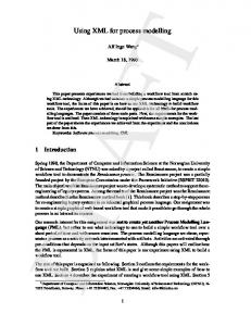
4 SPMA System Development SPMA prototype system has been built in order to automatically calculate metric for software processes in a design. This prototype system is implemented using two GNU C compiler tools, flex and bison, while its interfaces are built using Java language. There are four main entities in SPMA system. The first one is the User entity, which representing process designers whom will be using the system. The second entity is the Source File entity or as described before, the input to the system (the process model designs written in IDEF3-SPMA language). The third entity is the Syntax Rules, consisting of a set of syntax rules and measurement attribute calculation. The fourth entity is the Results entity, listings the calculated measurement attribute for a particular process model design. Figure 2 shows the context diagram for SPMA system.
User
System invocation
Syntax rules
Attribute Grammar Rules
SPMA System Source File
Token identifiers
Metric values
Tabulated results
Fig 2 SPMA system context diagram
The SPMA system runs on LINUX platform, which contain additional support for lex and yacc execution. Lex and yacc (or another version named as flex and bison) are tools designed to write compilers or interpreters (Mason and Brown, 1990). The structure of implementation stage taken by SPMA system using these two tools is as Figure 3 indicates.
4.1
SPMA Execution Description
There are four phases of operation in order to execute SPMA system. The first one is to get a problem or a requirement of a system, then the user must represent the process model in IDEF3 description before moving on to stage three, i.e. converting the representation into IDEF3SPMA language accordingly to the defined syntax rules. After that, if there is no syntax error found in the input lines, SPMA tool will execute and read the input to calculate its measurement metrics determined by the
Fig 3 Using flex and bison for SPMA implementation
system, otherwise, error messages will be listed out. Represented below is the example of how the system can be used. Phase 1: Get a scenario or a problem to be solved, where it should draft the module’s process flow before representing them in IDEF3. The flow may looks like Phase 2 below (or other flow, accordingly to the personnel’s problem solving skill): You are required to build a module that will be attached to an XYZ Company Bidding System. Your module should be able to list all biddings which fall into reasonable range of + and – values compared to original tender. Sign, Software Project Manager Phase 2: Represent the problem scenario in IDEF3 representation as shown in Figure 4. Process flow for Read-Rank-Bid Module: 1. Read bid 2. Compare the bid with the tender price, get the difference (either + or -)
IJCSNS International Journal of Computer Science and Network Security, VOL.7 No.8, August 2007
280
Phase 4: Run SPMA , and measurement metrics will be calculated and be displayed by opening the output file as shown in Figure 5.
3. Store the bidding with a reference number in BID database 4.Put a rank for the bid as per recent application 5. At closing date and time, list all biddings with reasonable ranged values, with its associative ranking. 6. Indicate the processes in IDEF representation as Figure 4 suggested. Read-Rank-Bid id
1
diff
rank
ref
sorted
id
Compare bid
Read bid 1.2
id
1.3
diff id ref
diff
Generate report
id ref
1.5
rank
rank
sorted
sorted
Get difference 1.3.6
Store bid and rank 1.4
Put rank diff
1.3.7
diff
rank
ref
sorted
Fig 5 An excerpt of corresponding output for problem Bid. Sort bid by difference 1.3.7.8
diff rank sorted
Associate with reference no. 1.3.7.9
Fig 4 Corresponding IDEF3 representation for problem Bid.
Phase 3: Convert IDEF3 representation into IDEF3-SPMA language process Read_Rank_Bid; proc read_bid (bid_id inout); read_bid :: {}; end_proc proc comp_bid (id in, rank out, diff out, sorted out, ref out); comp_bid (id in, rank out, diff out, ref out) :: sub {get_diff, put_rank}; get_diff (id in, diff out) :: {}; put_rank (diff inout, ref out) :: sub {sort, assoc_ref}; sort (diff in, sorted out) :: {}; assoc_ref (diff inout, ref out) :: {}; end_proc proc store_bid (id inout, rank in, diff in, sorted in, ref in); store_bid :: {}; end_proc proc generate_report (id inout, rank out, diff out, sorted out, ref out); generate_report :: {}; end_proc end
5. Results and Discussion Design phase is the most crucial and important part in developing software systems. From the output generated by SPMA system, the developer can view their process model design. However, a simple module like the example shown may not have a great impact from the usage of SPMA system, but when it is used for larger system, which requires more processes and build by separated teams, SPMA system can be very helpful in forecasting the difficulty of a ‘to-be-built’ software system. Other characteristic of this language-based metrics calculation tool is that it provides suggestions or advises for the users. The appropriate advice will be appended to the output file in terms of clarifying the meanings of the stated list of output. Advice in this context means to narrate the metric values and define what’s “Good” with the produced metric values (Westfall, 2003). Based on survey to six software analysts and process design experts (expert here means more than 10 years of experience in software design and development), the process model design size produced by this study is divided into three categories. Corresponding advices are given to define the “Good” out of the size value produced. The advices for the three categories are defined as follows: 1. Small: This category is for designs with size ranged from 1 to 300 elements in process structure. The advice given to this range is “This design falls into small model design category. The design can be
IJCSNS International Journal of Computer Science and Network Security, VOL.7 No.8, August 2007 implemented by three (3) persons per team within four (4) months. 2. Medium: This category is for designs with size ranged from 301 to 1000 elements in process structure. The advice given to this range is “This design falls into medium model design category. The design can be implemented by three (3) persons per team within eight (8) months. 3. Large: This category is for designs with size ranged from 1000 and above elements in process structure. The advice given to this range is “This design falls into large model design category. The design can be implemented by three (3) persons per team within sixteen (16) months.
References [1] Osterweil, L.J. Software Processes Are Software Too,
[2]
[3]
[4]
The narrated version of measurement values can be a more simple way in terms of categorizing process designs (Atan, 2005).
[5]
6. Conclusions
[6]
This research studies issues regarding the use of language to measure software process model design automatically. In order to achieve its objectives, this research has to scrutinize some related issues. The issues are such as software process model standards, languages for systems’ model design, design language translator, automatic process design metric collection, measurement metrics definition and what is “good” about the metric values produced. A set of measurement metrics has been defined, proved and tested accordingly. The metrics are then validated and verified to ensure their effectiveness. Since the research is about automatic software design measurement metric calculation, there must be certain notation or method to be followed by the designers. This is to ensure the uniformity of the design structure to be measured. Thus, a standardized approach is set to be the design technique and a language performing the design in language form is created in order for the design to be automatically executed and measured. This research shows that automatic collection of software process design measurement is able to ease designers in means of preliminary evaluation of their designs based on the verification of system. This research also produced a tool through extension of IDEF3 Standard, called SPMA that executes as a static analyser to IDEF3-SPMA language, which then summarizes and lists process model designs’ measurement metric attributes.
281
[7]
[8]
Revisited. In Proceedings of the 19th International Conference on Software Engineering. 1997; 540-548. Zamli, K.Z., Isa, N.A.M. and Khamis, N. The Design and Implementation of the VRPML Support Environment. The Malaysian Journal of Computer Science. 2005; 18(1). Frost, RA. Constructing Programs as Executable Attribute Grammars. The Computer Journal 1992; 35 (4). Mayer RJ, Menzel CP, Painter MK, DeWitte PS, Blinn T. and Perakath B. Information Integration for Concurrent Engineering (IICE): IDEF3 Process Description Capture Method Report. KBSI College Station, 1995. Texas Interim Technical Report for Period April 1992. 1995. Zakarian, A. and A. Kusiak, Analysis of Process Models. IEEE Transactions on Electronics Packaging Manufacturing. 2000; 23(2): 137- 147. Mason, T. and Brown, D. UNIX Programming Tools: lex & yacc. O’Reilly and Associates Inc., 1990. Westfall, L.L. Seven Steps to Designing a Software Metric. Benchmark QA: White Papers. http://www.benchmarkqa.com/index_resources_white papers.htm. Accessed on 13th January 2006. Atan, R. Use Of An Attribute Grammar For Software Process Measurement. Ph.D. Dissertation. Faculty of Computer Science and Information System, University Putra Malaysia. 2005.
Rodziah Atan received a Bachelor’s degree in Computer Science in 1996 from Agricultural University of Malaysia and Master Science in 1998 from Universiti Putra Malaysia. With research experience while her M.S. studies, she completed her PhD from the same university in 2005. She has been supported by the government of Malaysia and the University’s Young Lecturer Scheme (SLAB). Her field of interest is software process and business process modeling and pursuing for new knowledge in bioinformatics visualization tools. She is now one of the lecturers cum researcher in Universiti Putra Malaysia.