A Unified Model for Multicore Architectures
∗
John E. Savage
Mohammad Zubair
Brown University Providence,Rhode Island 02912
Old Dominion University Norfolk, Virginia 23529
[email protected]
ABSTRACT With the advent of multicore and many core architectures, we are facing a problem that is new to parallel computing, namely, the management of hierarchical parallel caches. One major limitation of all earlier models is their inability to model multicore processors with varying degrees of sharing of caches at different levels. We propose a unified memory hierarchy model that addresses these limitations and is an extension of the MHG model developed for a single processor with multi-memory hierarchy. We demonstrate that our unified framework can be applied to a number of multicore architectures for a variety of applications. In particular, we derive lower bounds on memory traffic between different levels in the hierarchy for financial and scientific computations. We also give a multicore algorithms for a financial application that exhibits a constant-factor optimal amount of memory traffic between different cache levels. We implemented the algorithm on a multicore system with two QuadCore Intel Xeon 5310 1.6GHz processors having a total of 8 cores. Our algorithms outperform compiler optimized and auto-parallelized code by a factor of up to 7.3.
Categories and Subject Descriptors G.4 [Mathematical Software]: Efficiency, Algorithm design and analysis
General Terms Algorithms, Performance, Experimentation
Keywords Memory Hierarchy, Multicore
1.
INTRODUCTION
∗ This paper appears in the Proceedings of IFMT’08, the First International Forum on Next-Generation Multicore/Manycore Technologies, Cairo, Egypt, November 2425, 2008.
[email protected]
Power consumption and heating constraints are limiting the instruction-level parallelism for improving processor performance. The response of the industry has been to increase the number of cores on a die. The effective use of these cores requires the parallelization of applications. Parallelization is a problem that arose in a serious way in the 1980s and 1990s. The use of multiple cores has introduced a new problem to parallel computing, namely, the management of hierarchical parallel caches. Multicore chips employ a cache structure to simulate a fast common memory. Unfortunately, the software to exploit these caches is lagging behind hardware development. To achieve high performance, applications executed on multicore chips need to be explicitly coded. To achieve good performance it is essential that algorithms be designed to maximize data locality so as to best exploit the hierarchical cache structure. While the efficient use of memory hierarchies is important in serial processors, it is doubly important in multicore architectures. Multicore processors have several levels of memory hierarchy. To obtain good performance on these processors it is necessary to design algorithms that minimize I/O traffic to slower memories in the hierarchy [22]. Researchers have extensively studied the problem of designing efficient algorithms for processors with memory hierarchy [15, 16, 26, 20, 18, 5, 21]. Processors with multiple cores are being manufactured by a number of vendors including IBM, Sun, Intel, AMD, and Tilera. At present most contain between 2 and 16 cores. However, a few contain as many as 64 to 80 cores. Plans exist to scale up chips to several hundred cores. Multicore processors are organized to share information across cores using fast buses or a switching network that limit the number of cores that can be accommodated. To scale processors to many cores, the trend is to organize the cores in a two dimensional grid with a router embedded with each core. One salient characteristics of multicore architectures is that they have a varying degrees of sharing of caches at different levels. Most architectures have cores with a private L1 cache. Depending on the architecture, an L2 cache is shared by two or more cores and an L3 cache is shared by four or more cores. The main memory is typically shared by all cores. The degree of sharing at a level varies from one multicore processor to another. In this paper, we explore these architectures from the memory hierarchy perspective. We propose a unified memory hierarchy model that captures
essential features of each of these architecture. Researchers in the past have explored various models for parallel computing starting with the PRAM [17]. The weakness of the PRAM model is that it ignores communication cost for moving data between processors. This is addressed by later models, for example the LPRAM [8], BSP [34], LogP [14], and Postal models [12]. These models ignored the memory hierarchy, which is addressed by the Memory Hierarchy Game [29] and several parallel hierarchical models such as LogP-HMM [28], LogP-UMH [10, 28], the Parallel Memory Hierarchy (PMH) model [11], and parallel versions [35, 37, 36, 25] of the serial memory hierarchy models of Aggarwal et al [6, 7]. One major limitation of all earlier models is their inability to model multicore processors with varying degrees of sharing of caches at different levels. In these models sharing happens for all processors at the level of main memory or through a network via the processors. By contrast, a multicore architecture can have an L2 cache shared by a subset of cores, and an L3 cache by a larger subset of cores, and so on. (The Intel Dunnington processor has an L2 cache that is shared by two cores, and an L3 cache that is shared by all six cores). In a multicore architecture we not only have varying degrees of sharing of caches at different levels, the degree of sharing at a level varies from one multicore architecture to another. For example, the Sun UltraSPARC T2 has an L2 cache that is shared by all eight cores as opposed to the Intel Dunnington processor that has an L2 cache that is shared by only two cores. In addition, all earlier models lack a general strategy that can help in deriving lower bounds for communication traffic within a core and across cores for different applications. Most of the efforts in deriving lower bounds are restricted to using strategies specific to an application and they work for a limited set of architectures. See for example [8, 37, 36, 24]. We introduce the Unified Multicore Model (UMM) that addresses all these limitations. It is an extension of the Memory Hierarchy Game (MHG) developed for a single processor attached to a hierarchy of memories [29]. The model assumes that sets of cores share first-level caches, these share second-level caches, etc. and that the cache capacity is the same for all caches at a given level. The UMM seamlessly handles different types of multiple-core processors with varying degrees of sharing of caches at different levels. We also provide a framework for deriving lower bounds on communication traffic between different levels of memory in the UMM. These bounds are useful to implementers for not only designing efficient algorithms, but also to see limitations of the architectures in achieving optimal performance. For example, the bounds can help to determine that the bandwidth available on the bus that interconnects main memory to caches at upper levels is not sufficient to achieve optimal performance. The proposed model works for straight-line computations all of which can be represented as directed acyclic graphs (DAGs). This includes matrix multiplication, FFT computation, and binomial option pricing, for example. To derive lower bounds for a given DAG, we first compute its
S-span [29]. The S-span intuitively represents the maximum amount of computation that can be done after loading data in a cache at some level without accessing higher levels (those further away from the CPU) memories. A more precise definition of S-span is given later. We demonstrate that the S-span of a DAG captures the computational dependencies inherent in the DAG and use it to develop lower bounds on communication traffic for a single core and multiple core architectures. Our model and associated analysis help in designing efficient multicore algorithms. We demonstrate that our unified framework can be applied to a variety of multicore architectures for a variety of applications. In particular, we derive lower bounds on memory traffic between different levels of hierarchy for financial and scientific computations. We also give a multicore algorithms for a financial application that exhibits a constantfactor optimal amount of memory traffic between different levels. We implemented these algorithms on a multicore system with two Quad-Core Intel Xeon 5310 1.6GHz processors with a total of 8 cores. We demonstrate that our algorithms outperform compiler-optimized and auto-parallelized code by a factor of up to 7.5. In Section 2 we describe a number of commercial multicore chips. This leads to the formulation of the UMM in Section 3. In Section 4 we model computations on the UMM as a multi-level pebbling game. General lower bounds on the communication traffic between caches in the UMM are derived in Section 6. In Section 7 we apply these bounds to three problems, a method for pricing options as well as matrix multiplication and the FFT algorithm. In Section 8 an implemention for a method of pricing options is described and analyzed. Conclusions are stated in Section 9.
2.
MULTICORE ARCHITECTURES
In this section, we describe the memory hierarchies associated with a number of important multicore architectures. Most of the architectures have a private L1 cache. Depending on the architecture, the L2 and L3 caches are typically shared by two or more cores.
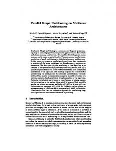
Sun UltraSPARC T2 The UltraSPARC T2 processor [4] has eight SPARC processor cores. A core has an 8-Kbyte, 4-way data cache. Each is connected through a crossbar to a 4 Mbyte, 16-way L2 cache. The L2 cache is banked eight ways to support eight cores and connects to four on-chip DRAM controllers, which directly interface to a pair of fully buffered DIMM (FBD) channels. (See Figure 1).
Intel Six-Core Dunnington Processor The Intel Dunnington processor [1] consists of six cores with each core having its own 96KB L1 data cache. The 3-MB L2 cache is shared by two cores. The 16-MB L3 cache is shared by all six cores. The interface to main memory is via a front side bus that operates at 1066 MT/seconds. (See Figure 2).
Sun Rock Processor with 16 Cores The Rock processor [33] is the latest 16-core SPARC system from Sun. It was scheduled to be released in 2008 but is now expected to be released in 2009. The Sun Rock processor
Core 0
Core 1
Core 7
8KB L1 Cache
8KB L1 Cache
8KB L1 Cache
Switch Cluster 0 Core 0
2MB Shared L2 Cache
Core 1
32KB Shared L1 Cache
Cluster 3 Core 2
Core 3
Core 12
32KB Shared L1 Cache
Core 13
32KB Shared L1 Cache
Core 14
Core 15
32KB Shared L1 Cache
System Memory Switch
Figure 1: The 8-Core Sun UltraSPARC T2 Processor
2MB Shared L2 Cache
System Memory
Core 0
Core 1
Core 4
Core 5
96KB L1 Cache
96KB L1 Cache
96KB L1 Cache
96KB L1 Cache
Figure 3: The Sun 16-Core Rock Processor
3 MB Shared L2 Cache
3 MB Shared L2 Cache
16 MB Shared L3 Cache
System Memory
Figure 2: The Intel 6-Core Dunnington Processor Core
consists of four clusters of four cores each, for a total of 16 cores. There is a 32KB dual banked 4-way L1 data cache that is shared by two cores. A 2MB 4-bank 8-way L2 cache is shared by all the cores. The memory hierarchy used by the Sun Rock Processor is illustrated in Figure 3.
Tilera 64-core Tile64 and Intel 80-core Tera-Scale Processors The Tile64 processor [3] consists of an 8×8 grid of processor cores. The Tile64 architecture eliminates on bus chip interconnect, which limits the number of cores that can be put on a chip. Each processor core has a communication switch that connects it to a two dimensional on-chip mesh network called the iMesh. A processor core has an 8KB L1 data cache and a 64 KB L2 cache. The architecture treats all the L2 caches together as a single large L3 cache. Multicore coherent caching enables data cached on a core to be accessed by other cores using the iMesh network. The block diagram illustrating the memory hierarchy for a single core is given in Figure 4. Intel is experimenting with a large number of cores in its Tera-Scale 80-core processor [2]. As with the Tilera processor, it connects cores in a 2D mesh.
8KB L1 Cache
64 KB L2 Cache
L3 Cache (Aggregation of L2 caches of all cores) (64 x 64 KB)
System Memory
Figure 4: Memory Hierarchy for a Single Core of a 64-Core Tile64 Processor from Tilera
SPE 0 (2KB)
SPE 1 (2KB)
SPE 7 (2KB)
256 KB Software Controlled Cache
256 KB Software Controlled Cache
256 KB Software Controlled Cache Core Level 0, p0
Element Interconnect Bus (up to 96 bytes/ cycle)
Level 1, p1
System Memory
Level 2, p2
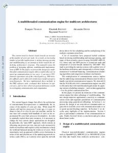
Figure 5: Memory Hierarchy for SPEs in a IBM, Sony, and Toshiba Cell Broadband Engine
IBM, Sony, and Toshiba Cell Broadband Engine Multicore Architecture IBM, Sony, and Toshiba have developed a multicore chip (the cell broadband engine) [19] that consists of eight synergistic processor elements (SPEs) and a PowerPC Processor Element (PPE). The SPE design is optimized for computationintensive applciations and the PPE is optimized for control tasks. The architecture for the SPE does not support a traditional cache-based memory hierarchy, although it does have a local store associated with each element under direct program control. The local store can be viewed as a software controlled cache where the data is moved between local store and memory using DMA. This simplifies the memory hierarchy hardware and moves the complexity to the programmer/compiler for managing local store. An SPE has a register file consisting of 128 registers of 128-bits each (2 KB of storage), and a local store of 256 KB. (See Figure 5).
3.
System Memory Level L-1, pL-1
Figure 6: The Universal Multicore Model in which pl denotes the number of cores sharing a common cache.
UNIVERSAL MULTICORE MODEL
In this section we introduce the universal multicore model (UMM) (see Figure 6) that captures the essential features of the multicore cache hierarchies described above. It assumes that each core sees L levels of memory including Level-0, which refers to registers and are typically part of the core. It also assumes that all caches at a level have the same size and that they are shared by the same number of cores. For our model, we define the following parameters for 1 ≤ l ≤ L − 1. pl : Number of cores sharing a cache at level-l
Product UltraSPARC T2 Dunnington Rock Tile64 Cell
Levels 4 5 4 5 3
Cores 8 6 16 64 8
p1 1 1 2 1 1
p2 8 2 16 1 1
p3 8 6 16 64 8
p4 6 64
αl : Number of caches at the lth level σl : Size of a cache at level-l Observe that pL−1 = p, the total number of cores. Because the number of cores sharing a cache at a given level is the same for all caches at that level, it follows that αl = p/pl . Parameters of the chips in Section 2 are given in Table 1.
4.
THE MULTICORE MEMORY HIERARCHY GAME
Table 1: The parameters of the multicore chips described herein.
In this section we introduce the multicore memory hierarchy game (MMHG), a pebbling game played on a DAG that models computations done on the UMM. It is an extension of the memory hierarchy game (MHG) introduced in [29] and generalized in [30, p. 535]. In Section 5 we improve upon previous lower bounds on the memory traffic required by the serial MHG. In Section 6 we extend this analysis to the UMM. The MMHG assumes that there are p cores and an L-level hierarchy of caches. Each level-l cache, 1 ≤ l ≤ L−1, is shared by pl cores. The MMHG assumes that all caches at level l have capacity σl and that the highest level cache or main memory has unlimited capacity. The sizes of caches at the various levels is represented by the tuple Σ = (σ1 , . . . , σL−1 ). It isn’t necessary to specify the size of the highest level memory because it is unlimited. The rules of the MMHG are given below. The purpose of the game is to pebble the output vertices of a graph G = (V, E). It is important to emphasize that the MMHG is a parallel pebbling game; pebbles associated with different caches can be placed and removed simultaneously. It is helpful to think of pebble moves as occuring synchronously, although this assumption is not strictly necessary. We are interested in the communication traffic between adjacent levels in the hierarchy. This is modeled by the number of times that a level-l pebble is placed on a vertex containing a level-(l − 1) pebble or vice versa.
4.1
Rules of the MMHG
We now state the rules for the multicore memory hierarchy game (MMHG). These rules generalize those for the memory hierarchy game (MHG) [29] that models data movement up and down a cache hierarchy for uni-processors. As mentioned above, in the MMHG multiple pebble moves can occur simultaneously as long as they don’t violate the rules.
R1. (Computation Step) A zero-level pebble associated with a core can be placed on any vertex all of whose immediate predecessors carry zero-level pebbles associated with that core. R2. (Pebble Deletion) Except for level-L pebbles on output vertices, a pebble at any level can be deleted from any vertex. R3. (Initialization) A level-L pebble can be placed on an input vertex at any time. R4. (Input from Level-l) For 1 ≤ l ≤ L − 1, a level-l pebble ξ associated with cache ci,l can be placed on any vertex carrying a level-(l + 1) pebble associated with the parent cache of ci,l . R5. (Output to Level-l) For 2 ≤ l ≤ L, a level-l pebble ξ associated with a cache ci,l can be placed on any vertex carrying a level-(l − 1) pebble associated with any cache cj,l−1 that is a child of ci,l . R6. Each output vertex must be pebbled with a level-L pebble.
Rule R1 states that a value associated with a vertex can be computed in a core only if the data on which the value depends are present in the core. Zero-level pebbles can slide from a predecessor to a successor vertex, which corresponds to using a register as both the source and target of an operation. The second rule states that data can be discarded. Rule R3 says that input data is available in the highest level cache and can be freely accessed. The fourth and fifth rules govern input from and output to level l. The fourth rule allows data associated with a vertex to move to level l from level l − 1 by placing a level-(l − 1) pebble on a vertex carrying a level-l pebble. Of course, this data movement is only possible from a cache to one of those caches to which it is connected. The fifth rule works in the same way except that it refers to movement from a lower level to the next higher one. The last rule states the goal of the pebble game, namely, to place a level-L pebble on each output vertex. This is tantamount to storing computed results in a permanent memory. Although the MMHG is a parallel pebbling game, it can be serialized. That is, we can pebble one vertex at a time. This restriction does not alter the vertices at which I/O operations are performed, just the total time for the operations. In memory hierarchies either the multilevel inclusion or exclusion policy is enforced. In the former policy a copy of the value in each location in a level-l cache is maintained in all higher level caches. These copies may be dirty, that is, not currently consistent with the value in the lowest level cache containing the original. They are updated as needed. The exclusion policy does not reserve space for values held in lower level caches. The rules given above are written for the exclusion policy. The results derived below are for the exclusion case. However, the results also hold for the inclusion policy when the memory associated with a cache in the lower bounds is the amount of memory over and above that used to hold copies of values in lower level caches. The MHG is the variant of the MMHG in which there is only one processor and one cache at each of L−1 levels. The level(L) L cache has unlimited size. We denote with Tl (Σ, G) the number of I/O operations at level l on the DAG G where Σ = (σ1 , . . . , σL−1 ) denotes the sizes of the caches.
5.
UNI-PROCESSOR LOWER BOUNDS
To set the stage for deriving lower bounds on communication traffic with the MMHG, we begin by describing the methods used to otain lower bounds for the MHG. The lower bounds rely on the S-span measure of a graph G.
Definition 1. The S-span of a DAG G, ρ(S, G), is the maximum number of vertices of G that can be pebbled in a zero-level pebble game starting with any initial placement of S red pebbles.
The S-span is a measure of how many vertices can be pebbled without doing any I/O. S pebbles are placed on the most fortuitous vertices of a graph and the maximum number of vertices that can be pebbled without doing I/O is the value of the S-span. Clearly, the measure is most useful for
graphs that have a fairly regular structure. It has provided good lower bounds on communication traffic for matrix multiplication, the Fast Fourier Transform, the pyramid graph and other graphs. This definition applies even if a DAG G is not a connected graph.
The following theorem derives lower bounds to the memory traffic under two conditions, a) the worst case when it isn’t known that the workload is balanced between cores and b) the case when the workload is uniformly distributed across all cores.
(L)
The following theorem derives a lower bound to Tl (Σ, G), the number of I/O operations at level l in the MHG. It is a generalization to hierarchical memories of a result of Hong and Kung [23]. The first version of this theorem appeared in [29]. The result given here improves upon the version given in [30, p. 535] by tightening the lower bound when the number of memory locations below level l is large. A proof of this theorem can be found in [32].
Theorem 6.1. Consider a pebbling of the graph G in an L-level universal memory hierarchy game with p processors. Let ρ(S, G) be the S-span of G and |V ∗ | be the number of vertices in G other than the inputs. Assume that ρ(S, G)/S is a non-decreasing function of S. Let βl−1 be the number of pebbles at level l − 1 and below in those caches having a cache at level l as parent. Let αl be the number of caches at level l.
Theorem 5.1. Consider a pebbling of the DAG G with n input and m output vertices in an L-level memory hierarchy game. Let ρ(S, G) be the S-span of G and |V ∗ | be the number of vertices in G other than the inputs. Assume that ρ(S, G)/S is a non-decreasing function of S.
For any allocation of workload to cores, for each l there is a (L) level-l cache such that the communication traffic, Tl,M (Σ, G), satisfies the following minimal lower bound.
Then, for 1 ≤ l ≤ L − 1 the communication traffic between (L) the lth and (l − 1)st levels, Tl (Σ, G), satisfies the followP ing lower bound where Σ(l−1) = l−1 r=1 σr is the number of pebbles at all levels up to and including level l − 1.
Also, Tl,M (Σ, G) ≥ S0 where S0 is the smallest value satisfying the bound ρ(2S0 , G) ≥ |V ∗ |/αl .
∗
(L)
Tl (L)
(Σ, G) ≥
Σ(l−1) |V | ρ(2Σ(l−1) , G)
(L)
Tl (Σ, G) also satisfies Tl (Σ, G) ≥ S0 where S0 is the smallest integer satisfying ρ(2S0 , G) ≥ |V ∗ |. It is also triv(L) ially true that Tl (Σ, G) ≥ (n + m).
(L)
Tl,M (Σ, G) ≥
βl−1 (|V ∗ |/αl ) ρ(2βl−1 , G)
(L)
When the workload is uniformly distributed over all cores, (L) the communication traffic at a level-l cache, Tl,U (Σ, G), satisfies the following bound. It is at least as strong as the above bound because ρ(S, G)/S is a non-decreasing function of S and αl /αl−1 ≤ 1. (L)
Tl,U (Σ, G) ≥
βl−1 (αl /αl−1 )(|V ∗ |/αl ) ρ(2βl−1 (αl /αl−1 ), G)
(L)
6.
MULTICORE LOWER BOUNDS
We now extend the above results to the uniform multicore model (UMM). We assume that the task of pebbling the vertices of a graph G with zero-level pebbles is shared among the cores and that no two cores perform the same computation. As with the serial model of computation, we assume that each vertex of a graph G is pebbled once with a zerolevel pebble by some core. Pebbles are local to either core registers or higher level caches. The number of I/O operations performed on a cache depends on the vertices of a graph G that are pebbled with zero-level pebbles by the cores sharing the cache. If these cores pebble very few (many) vertices, the number of I/O operations should be small (large). Let Ti,l (Σ, G) be the number of I/O operations for the ith cache at level l in the hierarchy where Σ = (σ1 , σ2 , . . . , σL−1 ) is the list of storage capacities of the caches in the UMM. We derive a lower bound to Ti,l (Σ, G) for the ith cache at level l whose cores pebble the largest number of vertices of G with zero-level pebbles. We generalize Theorem 5.1 to the UMM. Recall that the multicore memory hierarchy game (MMHG) is a parallel pebbling game in which it is possible to move multiple pebbles at the same time. We establish the following result by simulating the parallel pebbling of a graph in the UMM by a serial pebbling of the graph with two levels of pebbles.
Also, Tl,U (Σ, G) ≥ (αl−1 /αl )S0 where S0 is the smallest integer such that ρ(2S0 , G) ≥ |V ∗ |/αl−1 . Proof. The proof uses Theorem 5.1 for uni-processors. It has two parts. The first part consists of a lower bound to the I/O at level l in terms of the number of I/O operations in a two-level game. The important storage parameter is βl−1 , the number of memory locations in all the caches below level l that have a common level-l cache as parent. The second part consists of a lower bound on the I/O complexity for the two-level serial game. We extend the first result to the ith cache at level l in the UMM, denoted ci,l . Let Gi,l denote the subgraph of the graph G that is computed by the cores that have this cache as a parent. Recall that no zero-level vertex pebblings are done by more than one core. In the proof of Theorem 5.1 we argue that with two types of pebble we can simulate the restriction on the MHG. One type of pebble is used to simulate pebbles below level l. The second is used to simulate pebbles at or above level l. If we segment these pebbles into pebbles of the proper number at each of the levels of the hierarchy, the number of I/O operations at the level-l cache is that determined by the rules of the MHG. If, however, we now drop these restrictions and treat them as two types of pebble, we loosen the restrictions and derive a potentially smaller bound on the I/O at the level-l cache.
We apply the same type of reasoning here. We also argue that from the point of view of I/O operations at cache ci,l , there is no loss in assuming that the pebblings at levels ≤ l − 1 within the cores and caches that have ci,l as a parent are serial. The same is true for pebblings at higher levels or in other caches and cores. We use one type of pebble for levels ≤ l − 1 and a second type for levels ≥ l. The number of the second type of pebble is unlimited. Now consider pebbling Gi,l . We first derive a lower bound that holds for any allocation of work to cores. Let βl−1 be the total number of pebbles associated with all caches that share cache ci,l as a parent. Since there are αj /αl caches of capacity σj at level j that have ci,l as parent, P βl−1 = l−1 j=1 (αj /αl )σj . Consequently, we see that the number of I/O operations at cache ci,l satisfies the following lower bound. (L)
(2)
Ti,l (Σ, G) ≥ T2 (βl−1 , Gi,l ) We have reduced the number of I/O operations at a particular cache to the number of I/O operations in the serial two-level game. It remains to derive a lower bound for this number of I/O operations. We observe that in the UMM each cache ci,l is associated with a subgraph Gi,l . Since there are αl level-l caches, for some i, Gi,l has |V ∗ |/αl non-input vertices. Now we use the lower bound given in Theorem 5.1 (2) to T2 (S, Gi,l ) (2)
T2 (βl−1 , Gi,l ) ≥
βl−1 (|V ∗ |/αl ) ρ(2βl−1 , G)
from which the first lower bound follows. (2)
From Theorem 5.1 we also have that T2 (βl−1 , Gi,l ) ≥ S0 ∗ | where S0 is the smallest integer such that ρ(2S0 , G) ≥ |Vi,l where the latter is the number of non-input vertices in Gi,l . ∗ Since |Vi,l | ≥ |V ∗ |/αl , the second result follows. To derive the third result, which holds when the work is allocated uniformly to cores, we derive a lower bound to the traffic between a single level-(l − 1) cache, say, cj,l−1 and its parent, say ci,l . We multiply this traffic by αl−1 /αl , the number of level-(l−1) caches with ci,l as parent. The storage capacity of cj,l−1 and those caches for which it is a parent ∗ is βl−1 = βl−1 (αl /αl−1 ). Let Gj,l−1 be the subgraph computed by the cores that have cj,l−1 as parent. Then, a lower bound to the traffic between cj,l−1 and ci,l is given below. Since Gj,l−1 has |V ∗ |/αl−1 non-input vertices, we have the following. (2)
T2 (S, Gj,l−1 ) ≥
∗ (|V ∗ |/αl−1 ) αl−1 βl−1 ∗ αl ρ(2βl−1 , G)
(2)
For the last result we have that T2 (βl−1 , Gj,l−1 ) ≥ S0 ∗ where S0 is the smallest integer such that ρ(2S0 , G) ≥ |Vj,l−1 |≥ ∗ |V |/αl−1 . The traffic between all level-(l − 1) caches and a single level-l caches is (αl−1 /αl )S0 .
(n)
Figure 7: The graph Gbiop with depth n and n + 1 = 8 leaves.
7.
BOUNDS FOR SPECIFIC PROBLEMS
In this section, we investigate some common computations from financial and scientific domains and derive lower bounds on the number of I/O operations using the methodology given above. In the financial domain, we examine the option pricing computation using the binomial model. In the scientific domain, we study matrix multiplication and FFT computations.
7.1
Financial Computations
An option contract is a financial instrument that gives the right to its holder to buy or sell a financial asset at a specified price referred as the strike price, on or before the expiration date. Binomial option valuation is one popular discrete time methods of assigning a value to an option [27, 13]. The binomial option pricing computation is modelled by the (n) directed acyclic pyramid graph Gbiop of depth n and n + 1 leaves shown in Figure 7. Here the expiration time is divided into n intervals (defined by n + 1 endpoints), the root is at the present time, and the leaves are at expiration times. We (n) use Gbiop to determine the price of an option at the root node iteratively, starting from the leaf nodes. (n)
Gbiop models a computation with time of duration dt = T /n. (n)
In Gbiop the level increases as we go up the tree. We identify ith node at level j by (j, i), where 1 ≤ j ≤ n + 1 and 1 ≤ i ≤ n + 2 − j. As part of initialization we define asset and option prices at leaf nodes (j = 1). Asset price q√i1 at node (1, i) is given by qi1 = Qdn u(i−1) , where u = eν dt and d = u−1 . Here u and d indicate the fraction by which asset can go up or down respectively in one time interval. The initial price of the option at node (1, i), c1i , is simply the option payoff at the node, which is given by c1i = M AX(K − qi1 , 0) where K is the strike price. Next we iteratively compute option prices at nodes at level j +1 using prices at level j as defined below.
cj+1 i We now illustrate these results on a representative set of problems.
qij+1 cj+1 i
=
(pu cji+1 + pd cji )e−rdt
(1)
=
qij
(2)
∗u
= M AX(K −
qij+1 , cj+1 ) i
(3)
Here, cji and qij = Qdn u2(i−1)+j−1 are the option price and asset price respectively at (j, i). Also, pu and pd are pseudoprobabilities given by pu
=
pd
=
erdt − d u−d 1 − pu
We consider straight-line programs for the multiplication of two square matrices that perform the same set of additions and multiplications as the standard algorithm but in an arbitrary order. Such computations are described by DAGs. The result of multiplying two n × n matrices A and B is the matrix C = AB. The S-span of matrix multiplication is given in [30, p. 541].
The final output, cn+1 is the option price at the root node. 1 There are two types of options: European options, and American options. European options can only be exercised at the time of expiration, while American options can be exercised at any time prior to expiration. Note that computation (2) and (3) are only required for American options. From the communication traffic perspective the difference between American and European option is that American option requires access to an additional array that stores asset prices. The computation for a call option is similar except that the expression for payoff (3) is replaced by the following.
cj+1 i
= M AX(qij+1 − K, cj+1 ) i
In [31] we have obtained the following upper bound on the (n) S-Span of Gbiop .
Theorem 7.3. The S-Span of n × n matrix muliplication satisfies ρ(S, GM M ) ≤ 2S 3/2 . Applying Theorem 6.1 to GM M we have the following result. This result, in asymptotic form, was derived by Hong and Kung [23]. A concrete lower bound is due to Savage [29], [30, p. 542]. Using essentially the same basic proof technique, Irony et al [24] also derive a concrete lower bound but solely in the context of matrix multiplication. Theorem 7.4. When the workload in computing the n×n matrix multiplication graph is uniformly distributed across all cores, each level-l cache in the UMM requires a number of I/O operations satisfying the following bound where αl is the number of caches at level l and βl is the number of storage locations of caches that have a level-l cache as parent. √
Theorem 7.1. The S-Span of S(S − 1)/2.
(n) Gbiop
satisfies
(n) ρ(S, Gbiop )
(L)
Tl,U (Σ, GM M ) ≥
≤ (L)
αl−1 n2 (2n − 1) √ 3/2 p 2 2αl βl−1
1/3
Also, Tl,U (Σ, GM M ) ≥ αl−1 ((n − 1)n2 )2/3 /(25/3 αl ). (n)
Applying Theorem 6.1 to Gbiop we have the following result. Theorem 7.2. When the workload in computing the binomial graph on n + 1 inputs is uniformly distributed across all cores, each level-l cache in the UMM requires a number of I/O operations satisfying the following bound where αl is the number of caches at level l and βl−1 is the number of storage locations in all caches that have a given level-l cache as parent. (L)
(n)
Tl,U (Σ, Gbiop ) ≥ (L)
(n)
Also, Tl,U (Σ, Gbiop ) ≥
√
αl−1 n(n + 1) 4αl2 βl−1
αl−1 n/2αl .
Proof. The lower bound uses the fact that for all caches ci,l , 1 ≤ i ≤ αl , the number of non-input vertices in the subgraph pebbled by the cores that have ci,l as a parent is (n) |V ∗ |/αl . The value of |V ∗ | is n(n + 1)/2 for Gbiop . Using (n)
ρ(S, Gbiop ) ≤ S(S − 1)/2 ≤ S 2 /2 we have the lower bound. The second lower bound is obtained by multiplying S0 by (n) αl−1 /αl where ρ(2S0 , Gbiop ) ≥ |V ∗ |/αl . Using ρ(S, Gbiop ) ≤ S 2 /2 and replacing |V ∗ | by the lower bound n2 /2, the result follows.
7.2
Scientific Computations
Matrix Multiplication
Proof. The lower bound uses the fact that for all caches ci,l , 1 ≤ i ≤ αl , the number of non-input vertices in the subgraph pebbled by the cores that have ci,l as a parent is |V ∗ |/αl . The value of |V ∗ | is n2 (2n − 1) for GM M . Using ρ(S, GM M ) ≤ 2S 3/2 we have the lower bound. The second lower bound requires the smallest value of S0 satisfying ρ(2S0 , G) ≥ |V ∗ |/αl−1 . Since ρ(S, G) ≤ 2S 3/2 and |V ∗ | ≥ 2/3 2(n − 1)n2 , it follows that S0 ≥ ((n − 1)n2 )2/3 /(25/3 αl−1 ) from which the conclusion follows.
The Fast Fourier Transform Algorithm The complex Fourier Transform maps a tuple of complex coefficients a = (a0 , a1 , . . . , an−1 ) to a set of n values b = (b0 , b1 , . . . , bn−1 ) by evaluating the polynomial p(x) = a0 + a1 x + · · · + an−1 xn−1 at the roots of unity, that is, values in {ei2πj/n | 0 ≤ j ≤ n − 1} where bj = p(ei2πj/n ) and i is the solution to x2 = −1. The Fast Fourier Transform algorithm (FFT) is obtained by first writing p(x) = pe (x2 ) + xpo (x2 ) where pe (x2 ) (xpo (x2 )) is the polynomial consisting of the coefficients of p(x) of even (odd) degree. When the same decomposition is applied to pe (y) and po (y) and their subpolynomials, we obtain the FFT algorithm. It is represented by the butterfly graph. The S-span of the FFT graph is implicit in the the work of Hong and Kung [23]; a simplified proof the S-span is due to Aggrawal and Vitter [9]. See also [30, p. 546].
Theorem 7.5. The S-Span of the n-input FFT graph satisfies ρ(S, GF F T ) ≤ 2S log2 S.
Processor 1
Processor 0 Core 0
Applying Theorem 6.1 to GF F T we have the following result.
Core 2
Core 1
Core 0
Core 3
(L)
Also, Tl,U (Σ, GF F T ) ≥
n log2 n 4αl log2 (2βl−1 (αl /αl−1 ))
(n log2 n) . (4αl−1 )(log2 (n log2 n)−log2 (2αl−1 ))
Proof. The lower bound uses the fact that for all caches ci,l , 1 ≤ i ≤ αl , the number of non-input vertices in the subgraph pebbled by the cores that have ci,l as a parent is |V ∗ |/αl . The value of |V ∗ | is n log2 n for GF F T . Using ρ(S, GF F T ) ≤ 2S log2 S, the lower bound follows. The second lower bound requires the smallest value of S0 satisfying ρ(2S0 , G) ≥ |V ∗ |/αl−1 . Since ρ(S, G) ≤ 2S log2 S, it follows that S0 satisfies (2S0 ) log2 (2S0 ) ≥ a = (n log2 n)/(2αl−1 ). Straightforward substitution shows that if a ≥ 2, then 2S0 ≥ a/ log2 a. In this case, S0 ≥ (n log2 n)/((4αl−1 )(log2 (n log2 n) − log2 (2αl−1 ))). Multiplying by αl−1 /αl , we have the desired result.
8.
IMPLEMENTATION
In this section, we discuss the implementation on a multicore architecture of a representative application, option pricing. We propose and implement a multicore algorithm for binomial option pricing model. We implemented the proposed algorithms on a multicore system with two Quad-Cores Intel Xeon 5310 1.6GHz processors for a total of 8 cores described in Figure 8. A core has a 32KB L1 data cache. The 4MB L2 cache is shared by two cores. A single core of the Intel Xeon 5310 processor executes four floating-point instructions in one cycle, so the peak performance of a core is 6.4 GFLOPS with an overall peak of 51.2 GFLOPS for the complete system. In the UMM, α1 = 8, α2 = 4, α3 = 1. The sizes of caches in terms of the number of double-precision words holding values of ci and qi are σ1 = 2048, and σ2 = 256KB. To evaluate the performance of an algorithm, we use wall clock execution time. To evaluate how well a given algorithm matches the underlying architecture, we also compute algorithm performance as the percentage of the theoretical peak performance in gigaflops for the target machine. For example, when we get 25.6 GFLOPS on 8 cores of our test system, our code is running at 50% of the peak. All our algorithms were compiled using Intel Visual Fortran Compiler 10.1 on Windows XP Professional Operating System. We compiled all our code with “-fast” option, which combines various complementary optimizations for the target processor.
Core 3
Xeon
Xeon
Xeon
Xeon
Xeon
Xeon
Xeon
L1 Cache 32KB
L1 Cache 32KB
L1 Cache 32KB
L1 Cache 32KB
L1 Cache 32KB
L1 Cache 32KB
L1 Cache 32KB
L1 Cache 32KB
4MB Shared L2 Cache
4MB Shared L2 Cache
4MB Shared L2 Cache
4MB Shared L2 Cache
FSB
(L)
Core 2
Xeon
Theorem 7.6. When the workload in computing the ninput Fast Fourier Transform graph is uniformly distributed across all cores, each level-l cache in the UMM requires a number of I/O operations satisfying the following bound where αl is the number of caches at level l and βl is the number of storage locations of caches that have a level-l cache as parent. Tl,U (Σ, GF F T ) ≥
Core 1
FSB
System Bus
System Memory
Figure 8: A Dell PowerEdge 2990 system with two sockets and on each socket we have a Quad-Core Intel Xeon 5310 1.6GHz processor.
8.1
Vanilla Algorithm
Let us first look at issues in implementing a vanilla algorithm, which refers to a straightforward implementation of binomial option pricing without any explicit partitioning for parallelism. A high-level description of the code is given in Algorithm 1. Note that the main computation is done inside the two nested loops (lines 15-17). The compiler faces two challenges to obtain good performance for the vanilla code: a) effective utilization of the memory hierarchy; and b) distributing the computation amongst different cores for concurrent execution. Although compiler technology has made a lot of progress, it still cannot address some of these issues. The burden falls on the application programmer to partition a computation for effective utilization of the memory hierarchy and multiple cores. Algorithm 1 VanillaBinomial(Q, K, dt, n, r, ν) √
1: 2: 3: 4: 5: 6: 7: 8: 9: 10: 11: 12: 13: 14: 15: 16: 17: 18: 19: 20:
8.2
u ← eν dt d ← u−1 rdt −d pu ← e u−d pd ← 1 − pu p´u ← pu e−rdt p´d ← pd e−rdt {initialization loop} for i = 1 to n + 1 do qi ← Qdn u(i−1) {qi is a 1-d array} ci ← M AX(K − qi1 , 0) {ci is a 1-d array} end for {main computation loop} for j = 1 to n + 1 do for i = 1 to n + 1 − j do ci ← p´u ci+1 + p´d ci qi ← qi ∗ u ci ← M AX(K − qi , ci ) end for end for return c1
Multicore Algorithm
For a multicore architecture, we need to partition the computation into blocks such that multiple cores can work concurrently on different blocks and at the same time effectively utilize the memory heirarchy. We propose one such partitioning that is illustrated in Figure 9. For this partitioning,
0.25
b41
b32
b22
b21
Performance (% Peak)
b31
0.20
b23
0.15
0.10
0.05
b11
b12
b13
b14 0.00
m
64
128
256
512
1024
2048
4096
Block Size
Figure 9: Partitioning for a multicore architecture for n = 11 and block size m = 3.
all blocks in a single row, for example blocks in jth row with labels bj,∗ can be executed concurrently. We select a block size for this partitioning such that the required data for a block fits in the L1 cache of a core. Note that as we consider problem sizes up to a maximum of 64K leaf nodes, we can accommodate all the required data in a Level-2 cache. Thus for our experimentation, we ignored partitioning for Level-2. For the next level of memory, L0, which is the number of registers in the core, we rely on the compiler unrolling of the loop to block for registers. Processing of a block, for example, b32 requires m outputs each from blocks b22 and b23 that are processed as part of the previous iteration. A high-level description of the algorithm is shown in Algorithm 2. In our algorithm description, we use neb(bj,i ) to indicate the north-east boundary elements of bj,i and nwb(bj,i ) to indicate the north-west boundary elements of bj,i . To keep our presentation simple, we ignore processing of the first row of blocks, which is similar to other rows except that a block is an incomplete square and it does not require input from an earlier processed block. We also assume that m evenly divides n + 1. If these assumptions are not correct, the run times are changed by small constant factors. (n)
Algorithm 2 Gbiop do 1: for j = 2 to n+1 m 2: {OpenMP thread directive is placed here} − j + 1 do 3: for i = 1 to n+1 m 4: processSquare(bj,i , neb(bj−1,i ), nwb(bj−1,i+1 )) 5: end for 6: end for The output of neighbor bj−1,i , north-east boundary, that is required for processing bj,i is stored as part of the shared array that holds the option prices. We do in place computation in the shared array as we move from one level to next similar to the vanilla algorithm. The ith element of the shared array after processing nodes at level j holds the option price for node (j, i). The output of the neigbor bj−1,i+1 , north-west boundary, that is required for processing of bj,i is stored separately from the shared array. To minimize the storage requirement, we reuse the array that stores northwest boundary of bj−1,i+1 to store north-east boundary of bj,i .
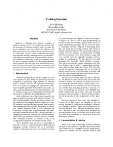
Figure 10: Execution time as a function of block size
Observe that a large block size for L1 results in an unbalanced load distribution amongst cores. For a given problem size, there is an optimal block size for L1 as seen from the plots of Figure 10. The other factor that influences the load distribution is how various blocks are mapped to different cores. We use OpenMP directives to parallelize the computation across different cores. We use a work-sharing directive of OpenMP to distribute the iterations of the inner loop of Algorithm 2 among different cores using eight threads, one for each core. The openMP directives are placed just before the second loop (line 2). Observe that processing of a block bj,i in line 3 requires input from blocks that were processed in previous iteration j − 1. Hence the blocks in the current iteration can be concurrently executed. The work load for each thread (core) is decided by the schedule directive of OpenMP. There are three main types of schedules supported in OpenMP, namely static, dynamic, and guided. We experimented with different schedules and found that the static schedule with chunk size of one gave optimal performance. The chunk size greater than one for all schedules results in low performance due to unbalanced load distribution among cores. We use the KMP AFFINITY environment variable to control binding of a thread to a physical core for optimal scheduling.
Analysis We first estimate the memory traffic between an L2 cache and one of its children L1 caches. We then multiply it by two (4) to get the estimate for T2 . Observe that our partitioning results in nb(nb + 1)/2 blocks, where nb = (n + 1)/m. When n is large compared to the block sizes and the number of cores, the number of blocks is large and they are almost uniformly distributed among the various cores. Because there are eight cores, the number of blocks allocated to a core is approximately n2 /16m2 . A typical block has m2 entries, m at the midpoint and m(m − 1)/2 above and below the midpoint. To compute it requires that the northeast and northwest boundaries of two neighboring blocks be provided. The number of data items is 2m. We assume that these values are not available in the L1 cache. The estimate for memory traffic between one L2 cache and one of its child L1
caches is given by „
(4)
T2 /2 ≈ 2m (4)
≈
T2
n2 16m2
n2 4m
From Theorem 7.2, the lower bound for (4)
T2
≥
Table 2: Execution time for the binomial algorithm using OpenMP
«
Execution Time (Seconds) (4) T2
is given by
α1 n(n + 1) 4α22 β1
n+1
1 Core
2 Cores
4 Cores
8 Cores
8192 16384 32768 65536
0.094 0.372 1.414 5.634
0.050 0.192 0.723 2.848
0.028 0.102 0.379 1.468
0.017 0.058 0.208 0.770
For our system α1 = 8, α2 = 4 and for β1 = 2m we get the following lower bound. (4)
T2
≥
n(n + 1) 16m
Table 3: Performance of the binomial algorithm as percentage of theoretical peak % Peak
Thus the proposed algorithm performance can be bounded by a constant factor of 4 away from the lower bound. Observe that we assume the L1 cache holds m words or that σ1 = β1 /2 = m. For our system, σ1 = 2048 data values. Considering load balancing issues as discussed earlier, when m = 2048 and the problem size is small, the performance of the algorithm can be far from optimal. This is due to an artifact of our lower bounds, which ignores load balancing issues. It may be possible to strengthen our bounds by considering these issues. Because our system has a large L2 cache for the problem sizes considered, we do not have (4) a strong bound for T3 , which is trivially bounded by the (4) number of inputs. Hence we ignore T3 from our analysis.
Performance We summarize our results in Tables 2 to 5. Our algorithm performs better for large problem sizes. We achieve 33% of the peak performance for 64K problem size versus 23% of the peak performance for the 8K problem size on 8 cores. For the 64K size problem, we obtained 16.7 GFLOPS. Similarly we observed a better scalability for large problem sizes. For example, we obtained a speedup of 7.3 for the 64K size problem on 8 cores versus a speedup of 5.5 for the 8K size problem on 8 cores. For comparison, we also implemented a vanilla algorithm, which refers to a straightforward implementation of binomial option pricing without any explicit partitioning for parallelism. We compiled the vanilla code with the “-fast” option along with the “-Qparallel” option that enables the autoparallelizer to generate multithreaded code for loops that can be safely executed in parallel. Our results for the vanilla algorithm are summarized in Table 6. The best performance for the vanila algorithm is 4% of the peak as compared to 33% of the peak for our algorithm.
n+1
1 Core
2 Cores
4 Cores
8 Cores
8192 16384 32768 65536
33% 34% 36% 36%
32% 33% 35% 35%
28% 31% 33% 34%
23% 27% 30% 33%
Table 4: Performance of the binomial algorithm in GFLOPS GFLOPS n+1
1 Core
2 Cores
4 Cores
8 Cores
8192 16384 32768 65536
2.1 2.2 2.3 2.3
4.0 4.2 4.5 4.5
7.2 7.9 8.5 8.8
11.7 14.0 15.5 16.7
Table 5: Scalability performance of the binomial algorithm Speedup n+1
1 Core
2 Cores
4 Cores
8 Cores
8192 16384 32768 65536
1.0 1.0 1.0 1.0
1.9 1.9 2.0 2.0
3.4 3.6 3.7 3.8
5.5 6.5 6.8 7.3
Table 6: Performance of the vanilla-binomial algorithm using ”-fast” and ”-Qparallel” compiler options for optimization and auto-parallelization n+1 8192 16384 32768 65536
Execution Time (sec) 0.09 0.38 1.53 6.14
GFLOPS
% Peak
2.15 2.15 2.10 2.10
4.2% 4.2% 4.1% 4.1%
9.
CONCLUSIONS
In this paper, we present a unified memory hierarchy model for multicore architectures that have a varying degree of sharing of caches at different levels. We also present a general strategy that can help in deriving lower bounds for communication traffic for a single core and multiple cores for different applications. We show that the S-span of a DAG captures the computation dependencies inherent in the DAG and use it to develop lower bounds on communication traffic for a single core and multiple cores. We demonstrate that our unified framework can be applied to a variety of multicore architectures for a variety of applications. We also give multicore algorithms for a financial application that exhibit a constant-factor optimal amount of memory traffic between different levels. We implemented these algorithms on a multicore system and demonstrated that our algorithms outperform compiler-optimized and auto-parallelized code by a factor of up to 7.3. One of the limitations of our model is that it works for straight-line computations all of which can be represented as DAGs.
10.
[12]
[13]
[14]
[15]
[16]
[17]
ACKNOWLEDGMENTS
This work was supported in part by NSF Grant CCF-0403674.
[18]
11.
[19]
REFERENCES
[1] Intel’s multicore architecture briefing, 2008. http://www.intel.com/pressroom/archive/ releases/20080317fact.htm. [2] Teraflops research chip, 2008. http://techresearch. intel.com/articles/Tera-Scale/1449.htm. [3] TILE64 processor family, 2008. http://www.tilera.com/products/processors.php. [4] UltraSPARC T2 Processor – Overview, 2008. http://www.sun.com/processors/UltraSPARC-T2/. [5] R. C. Agarwal, F. G. Gustavson, and M. Zubair. Exploiting functional parallelism of POWER2 to design high-performance numerical algorithms. IBM J. Res. Dev., 38(5):563–576, 1994. [6] A. Aggarwal, B. Alpern, A. Chandra, and M. Snir. A model for hierarchical memory. In Proceedings of 19th Annual ACM Symposium on the Theory of Computing, pages 305–314, New York, 1987. [7] A. Aggarwal, A. Chandra, and M. Snir. Hierarchical memory with block transfer. In 28th Annual Symposium on Foundations of Computer Science, pages 204–216, Los Angeles, California, October 1987. [8] A. Aggarwal, A. K. Chandra, and M. Snir. Communication complexity of PRAMs. Theor. Comput. Sci., 71(1):3–28, 1990. [9] A. Aggarwal and S. V. Jeffrey. The input/output complexity of sorting and related problems. Commun. ACM, 31(9):1116–1127, 1988. [10] B. Alpern, L. Carter, E. Feig, and T. Selker. The uniform memory hierarchy model of computation. Algorithmica, 12(2/3):72–109, 1994. [11] B. Alpern, L. Carter, and J. Ferrante. Modeling parallel computers as memory hierarchies. In Proceedings of the 1993 Conference on Programming
[20]
[21]
[22]
[23]
[24]
[25]
[26]
[27]
Models for Massively Parallel Computers, pages 116–123, 1993. A. Bar-Noy and S. Kipnis. Designing broadcasting algorithms in the Postal model for message-passing systems. Math. Syst. Theory, 27(5):431–452, 1994. J. C. Cox, S. A. Ross, and M. Rubinstein. Option pricing: A simplified approach. Journal of Financial Economics, 7(3):229–263, September 1979. D. Culler, R. Karp, D. Patterson, A. Sahay, K. E. Schauser, E. Santos, R. Subramonian, and T. von Eicken. LogP: towards a realistic model of parallel computation. SIGPLAN Not., 28(7):1–12, 1993. J. J. Dongarra, J. DuCroz, S. Hammarling, and R. Hanson. An extended set of Fortran basic linear algebra subprograms. ACM Trans. on Math. Soft., 14:1–17, 1988. J. J. Dongarra, J. DuCroz, S.Hammarling, and R. Hanson. Algorithm 656: An extended set of Fortran basic linear algebra subprograms: Model implementation and test programs. ACM Trans. Math. Soft., 14:18–32, 1988. S. Fortune and J. Wyllie. Parallelism in random access machines. In STOC ’78: Proceedings of the tenth annual ACM symposium on Theory of computing, pages 114–118, New York, NY, USA, 1978. ACM. K. Goto and R. A. van de Geijn. Anatomy of high-performance matrix multiplication. ACM Trans. Math. Softw., 34(3):1–25, 2008. M. Gschwind, H. P. Hofstee, B. Flachs, M. Hopkins, Y. Watanabe, and T. Yamazaki. Synergistic processing in Cell’s multicore architecture. IEEE Micro, 26(2):10–24, 2006. A. Gupta, F. G. Gustavson, M. Joshi, and S. Toledo. The design, implementation, and evaluation of a symmetric banded linear solver for distributed-memory parallel computers. ACM Trans. Math. Softw., 24(1):74–101, 1998. F. G. Gustavson. High-performance linear algebra algorithms using new generalized data structures for matrices. IBM J. Res. Dev., 47(1):31–55, 2003. J. L. Hennessy and D. A. Patterson. Computer Architecture: A Quantitative Approach. Morgan Kaufmann, San Francisco, CA, 2007. J.-W. Hong and H. T. Kung. I/O complexity: The red-blue pebble game. In Proc. 13th Ann. ACM Symp. on Theory of Computing, pages 326–333, 1981. D. Irony, S. Toledo, and A. Tiskin. Communication lower bounds for distributed-memory matrix multiplication. J. Parallel Distrib. Comput., 64(9):1017–1026, 2004. B. H. H. Juurlink and H. A. G. Wijshoff. The parallel hierarchical memory model. In SWAT ’94: Proceedings of the 4th Scandinavian Workshop on Algorithm Theory, pages 240–251, London, UK, 1994. Springer-Verlag. B. K˚ agstr¨ om, P. Ling, and C. van Loan. GEMM-based level 3 BLAS: high-performance model implementations and performance evaluation benchmark. ACM Trans. Math. Softw., 24(3):268–302, 1998. Y. Kwok. Mathematical Models of Financial
Derivatives. Springer-Verlag, Singapore, 1998. [28] Z. Li, P. H. Mills, and J. H. Reif. Models and resource metrics for parallel and distributed computation. In HICSS ’95: Proceedings of the 28th Hawaii International Conference on System Sciences (HICSS’95), page 51, Washington, DC, USA, 1995. IEEE Computer Society. [29] J. E. Savage. Extending the Hong-Kung model to memory hierarchies. In D.-Z. Du and M. Li, editors, Computing and Combinatorics, pages 270–281. Springer-Verlag, Lecture Notes in Computer Science, 1995. [30] J. E. Savage. Models of Computation: Exploring the Power of Computing. Addison Wesley, Reading, Massachusetts, 1998. [31] J. E. Savage and M. Zubair. Cache-optimal algorithms for option pricing, 2008. Submitted for publication. [32] J. E. Savage and M. Zubair. Memory hierarchy issues in multicore architectures. Technical Report CS-08-08, Department of Computer Science, Brown University, 2008. [33] M. Tremblay and S. Chaudhry. A third-generation 65nm 16-core 32-thread plus 32-scout-thread CMT c processor, 2008. http: SPARC //blogs.sun.com/HPC/resource/RockISSCC08.pdf. [34] L. G. Valiant. A bridging model for parallel computation. Commun. ACM, 33(8):103–111, 1990. [35] J. S. Vitter and E. A. M. Shriver. Optimal disk I/O with parallel block transfer. In STOC ’90: Proceedings of the twenty-second annual ACM symposium on Theory of computing, pages 159–169, New York, NY, USA, 1990. ACM. [36] J. S. Vitter and E. A. M. Shriver. Algorithms for parallel memory I: two-level memories. Algorithmica, 12(2/3):110–147, 1994. [37] J. S. Vitter and E. A. M. Shriver. Algorithms for parallel memory II: hierarchical multilevel memories. Algorithmica, 12(2/3):148–169, 1994.