support for running isolated networks for different ser- vices on top of a ... Index Termsâ Use cases, network virtualization, fu- ... technology, several steps have to be taken. First of all, .... a single contractual relationship offering customer care.
A USE CASE DRIVEN APPROACH TO NETWORK VIRTUALIZATION D. Schlosser, M. Jarschel, M. Duelli, T. Hoßfeld
K. Hoffmann, M. Hoffmann, H.-J. Morper
D. Jurca, A. Khan
University of W¨urzburg, Institute of Computer Science, W¨urzburg, Germany
Nokia Siemens Networks GmbH & Co. KG, Munich, Germany
DOCOMO Communications Laboratories Europe GmbH, Munich, Germany
ABSTRACT
increasing number of users connect to the Internet using a wireless link, which currently cannot provide the same Quality of Service (QoS) as a fixed network. Second, the Internet is changing from an everywhere network to a ‘real-time’ network. It is no longer sufficient to get information from one place to another. The information should be available everywhere in real time, independent of the type of information. The customer does not differentiate between short twitter messages and HD video clips. The Internet architecture is still bound to its best effort basis and will not be able to satisfy these demands.
In today’s Internet, services are very different in their requirements on the underlying transport network. In the future, this diversity will increase and it will be more difficult to accommodate all services in a single network. A possible approach to cope with this diversity within future networks is the introduction of support for running isolated networks for different services on top of a single shared physical substrate. This would also enable easy network management and ensure an economically sound operation. End-customers will readily adopt this approach as it enables new and innovative services without being expensive. In order to arrive at a concept that enables this kind of network, it needs to be designed around and constantly checked against realistic use cases. In this contribution, we present three use cases for future networks. We describe functional blocks of a virtual network architecture, which are necessary to support these use cases within the network. Furthermore, we discuss the interfaces needed between the functional blocks and consider standardization issues that arise in order to achieve a global consistent control and management structure of virtual networks.
The objective of the COMCON project (COntrol and Management of COexisting Networks)[1] is to design novel control and management mechanisms that support the coexistence of virtual networks in a future networking scenario and to illustrate their economic advantages. Virtualization technology is a key component that not only acts as an abstraction layer between services and infrastructure to facilitate innovation, but also is an integral part of the overall design to support the evolution and coexistence of different network architectures. Hence, interfaces between functional roles in coexisting networks, realized by network virtualization, are specified. Provider- and operator-grade management and control functions of coexisting virtual networks are built, which also integrates an end-to-end view to reflect the users’ perception. These functions comprise of isolation, dynamic reassignment of resources, and efficient and effective monitoring of virtual networks.
Index Terms— Use cases, network virtualization, future Internet architecture, standardization 1. INTRODUCTION
In order to make network virtualization a successful technology, several steps have to be taken. First of all, use cases need to be defined, which demonstrate the advantages of network virtualization and cannot be implemented using current Internet technology due to excessive costs or missing functionality. In a second step, we can evaluate different architectural options regarding these use cases to identify essential functional units and revise parts, which can not fulfill the needs of these use
The Internet of today provides access to many services, e.g., email, web, and file transfers, but its structure is inflexible and it is hard to introduce new network services. Furthermore, we currently notice two trends, which will influence the future of the Internet. First, an This work was funded by the Federal Ministry of Education and Research of the Federal Republic of Germany (F¨orderkennzeichen 01BK0917, GLab). The authors alone are responsible for the content of the paper.
1
cases. The interfaces between these functional units need to be defined and standardized in cooperation with hardware manufacturers in order to shorten the time to market period. The remainder of this contribution is structured as follows. We present three use cases in Section 2, which should be supported in future networks. In Section 3, we describe our virtual network infrastructure needed to realize the described use cases. In Section 4 we derive interaction points within this infrastructure. Related work is presented in Section 5. Finally, we conclude this work and give an outlook on our future work in Section 6.
Phase 1
Phase 2 Phase 3
Phase n
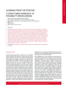
Fig. 1. Beta Slice extending its size and reach
network with a small number of hops and a limited geographical reach. The users accessing this network will be restricted to a small number, which the service provider can individually select. With this setup, the service provider is able to perform its initial evaluation and basic functionality tests. If this start up phase is successful, the number of network hosts, the network reach and the number of participating users can easily be increased. With this larger environment other tests can be performed, which evaluate other functions or consider more inhomogeneous network characteristics, i.e. wired networks and wireless connected end hosts. Progressively expanding the network and testing the functionality of the service enables development strategies, which are common in software development but cannot economically be implemented for network protocols these days. Furthermore, this use case allows to test the scalability of a new service in a real world environment and not only in a simulated or emulated environment. Another benefit of this use case is that the time to market can be significantly decreased.
2. USE CASES FOR FUTURE NETWORKS We consider future networks to be different from today’s networks in some aspects. There are many different kinds of traffic such that it is not economically feasible to build one network that can satisfy all needs, c.f. [2]. Hence, we consider that in the future there will be different networks sharing the same physical infrastructure but being isolated from each other. This means that each network is autonomous in its functionality and that there is no traffic interference, i.e. overload situations in one network do not affect the other networks. In this situation it is no longer necessary, that the operator of a network is the owner of the hardware. Therefore, we consider at least three basic roles: the first role is owning and operating the physical infrastructure. The second role assists in the creation of parallel networks and unifies the management view. The third role operates the networks running on top. Although these three roles are functionally different, all roles can be taken by the same company. In the following sections we consider three use cases, that take advantage of these enhancements and add value to the network.
2.2. Service Broker in Access Networks As IP-based home communication services, data and telecommunication services, mobile services, and data storage will converge more and more in the near future, the users’ homes get into the focus of all service providers. In addition to telephony and broadband data access – which are traditionally provided by access providers – new services are introduced to the homes. For instance, video on demand and Pay TV providers try to place their set top-boxes in the households. Also mobile network operators try to gain a foothold there. Besides the ongoing competitions for the user access there will be an increasing need to offload cellular user traffic at the users’ homes. The users are in a comfortable position. They can choose from a variety of services and service providers. However, they are reluctant to have individual contracts for each service, but prefer all-inclusive flat rate packages with only one
2.1. Beta Slice The name Beta Slice describes a single isolated network that supports the development and roll out of new services. Nowadays, new network services are usually developed in small dedicated test beds. These test beds are expensive and in most cases scalability cannot be investigated. In a future network, this problem can be solved if it is possible to run different networks in parallel whose resources and reach can be adopted easily, c.f. Figure 1. For the Beta Slice use case, we consider a service provider that has invented a new service, e.g. a new network protocol or a new application service which needs special network features. Instead of creating a specialized test bed the service provider will create a 2
TV provider to the set-top-box and the mobile network operator to the femto access point. 2.3. Service Component Mobility in Mobile Networks Due to the proliferation and interconnection of mobile networks, users can nowadays enjoy connectivity almost everywhere. However, technical challenges still remain, and sometimes users may face difficulties in accessing their preferred services in a far away location. We envision a future where not only the users are mobile, but also the services, in order to reduce access latency and network resource consumption. A service component can be an application software, e.g. a Hindi-German translation software, a transcoder module to process a video stream or file at an optimized place in the network, a cache containing video clips, users’ personalized webpages containing their preferred multimedia contents, etc. These entities will move from one place in the network to another in order to better serve the users. A translation software in the network can roam with a cellular user into in another country e.g. from Germany to India. It would impose significant network delay if the roaming user in India connects to the home network in Germany to access the service. It will be even more critical if the service is necessary in real-time e.g. during a voice conversation. In this case, the translation service component will migrate to the visited network, in this example, to India, and provide real-time translation to the user, c.f. Figure 3. The same principle can be used for mobile cache distribution. In this cases, it could also economically make sense to place the service component in a suitable network location, moving content closer to the access network to address flash crowds and save network resources etc. However, it is an ambitious challenge to realize such scenarios from the technological perspective. We must provide application layer functionalities at the routers
!
Fig. 2. Service Broker
contractual partner who provides all required hardware and software. Obviously, these requests somewhat collide with a scenario where hardware from different providers shall be placed at the users’ residence. Only in few cases, a single operator is able to offer all the services that are on the users’ wish list. Moreover, users might want to have services that are offered by competing service providers. But the user’s request for a single contractual relationship offering customer care for all services. This situation calls for a new mediating player, who is accepted by all service providers and the user. This player will act as a service broker who offers individualized packages to customers. Preferably, this player will also take care of providing necessary hardware and software. Furthermore, the service broker will enable service providers contributing to the package to exclusively control the hardware and software required for its service. Thus this service broker provides means to selectively assign individual controllership to different service providers. The selective controllership has impact throughout the transport networks since services are configured endto-end, between service providers and user equipment, steered by service brokers. In order to assemble the best solution for the user, the service broker will take the users’ ‘wish lists’ and select those appropriate service providers that best match the users’ demands, c.f. Figure 2. Next it configures the components at the users’ homes – which are shipped by the service broker as part of the package – in such a way that the service providers get exclusive control over those functions that are necessary for service delivery, i.e. a Pay
!"#$%&'(*!
!"#$%&'()! ,"&3/4"(&%-./01(%2#!
+,"&(&%-./01(%2#!
Fig. 3. Service Component Mobility 3
,"&3/4"(( 4%.5%0"0#!
A PIP creates virtual resources on its hardware and offers these resources to its customers. The virtualization techniques have to support strict isolation of virtual resources as explained earlier. This means that overload on one virtual resource does not effect other virtual resources on the same physical resource. The parameters and properties of the virtual nodes and virtual connections, which the PIP offers to a customer, are described by SLAs. Hence, the PIP and its customer have to negotiate a contract including SLAs with the properties of the virtual network the PIP provides. As the PIP has direct access to the physical substrate, it is able to measure the utilization of its physical resources. Furthermore, if the virtualization technology is able to support seamless migration of nodes and connections without effecting the topology and SLAs for the resources, the PIP will be able to move virtual resources. This enables the PIP in low load situations to move many virtual nodes on the same physical node and switch off the spare hardware resources in order to save energy costs. Additionally, the PIP can take advantage of the knowledge of all the SLAs contracted on virtual resources hosted by this hardware. Combining this knowledge with exact utilization measurements, the PIP is able to overbook its physical resources. Another important function of the PIP is to protect network links with resilience features. Only the PIP knows where exactly in the physical network the virtual resources are located and it is able to move the virtual resources on his physical substrate, as long as the topology and SLAs are kept. It is the only one to implement a virtual connection that relies on two disjoint paths in the real world.
or close to the routers, such that application software can migrate there when appropriate. We must also define and standardize middleware platforms on which a migrating service component can accommodate itself seamlessly over multiple operators. Finally, we must ensure security, so that malicious software cannot proliferate on such platforms. 3. COMCON VIRTUALIZED ENVIRONMENT We consider network virtualization to be the enabler for the described use cases, which require the isolation of parallel running networks and separation of the network logic from the underlying hardware. In a virtual network environment, the tasks to operate a network are the same as in a scenario without virtualization, but it is no longer necessary, that one company is owning, operating, and managing the physical hardware and the network on top. Hence, we do not consider a classic ISP role model. Instead, we characterize roles according to their functional aspects. Basically, we distinguish five functional roles. 1) The physical infrastructure provider (PIP) owns and operates the hardware and offers virtualized resources. 2) Virtual network providers (VNPs) gather these virtual resources and construct virtual networks. 3) A virtual network operator (VNO) requests networks with special requirements, e.g. setting up a service level agreement (SLA), and brings them to life, i.e. it installs the hosts, defines the protocols, and controls the network. At the edges of the network 4) end-customers (EC) and 5) application service providers (ASP) request and offer services, which are delivered in high quality by the virtual networks. Figure 4 provides an overview of the stacking of the functional roles.
The second functional role is the virtual network provider (VNP). The main function of the VNP is to gather resources from a single or differnet PIPs and combine them to create a virtual network.
COMCON – Objective: Network Virtualization
The VNP provides interfaces between the PIPs and the VNO to install software and protocol stacks on the virtual nodes. The VNP might want to reserve a pool of virtual resources in order to react quickly on its customer’s wishes. On a global market, it is reasonable that there are some VNPs, which only contract certain PIPs and vice versa. Therefore, it is possible for a VNP to request parts of the network he offers from another VNP. The VNP providing a part of the network of another VNP will act as a subcontractor.
Service Provider
Customer
VN optimization, control and management
VNO Optimized combination and splitting of virt. resources
VNP Virtualization of multi-x networks
PIPs Customer PIPs
Access PIPs
Transport PIPs
Server PIPs
Transport PIPs
Access PIPs
Michael Jarschel, Tobias Hossfeld
Service Provider PIPs
The third functional role is the virtual network operator (VNO). The VNO requests a virtual network from a VNP. The VNO uses the interfaces provided by the VNP to install software and network stacks on the virtual nodes. With this setup, the VNO operates and optimizes the network according to its purpose, e.g. a special broadcast network, which is optimized for a certain service like IP-TV or a content distribution network. The network could also support other features like ex-
!
Fig. 4. Stacking of functional roles We call all forms of hardware and transport media, which are used to establish the connection between two end hosts, the physical substrate of the network. The entities that own and operate this substrate are called physical infrastructure providers (PIPs). 4
tended security to provide secure banking or cooperate networks. The VNO controls how, which kind of data is transported in the network. He takes care of the operation and maintenance of the virtual network nodes. Furthermore, he keeps a close watch on how the network reacts on network service degradations. If the network does not transfer data as expected, the VNO has to locate the problem and act accordingly. If the problems are caused by some part of the networks, which does not operate within the requested parameters the VNO has to report the SLA breach to the VNP. Otherwise, the VNO will adopt the operation of the network. This could cover changing settings of the deployed virtual nodes or requesting new resources. Finally, we consider the role of the application service provider (ASP) and the end customer (EC), which can be a user or an enterprise. The ASP provides the service to be delivered and the target group, i.e. it specifies a service coverage area. Furthermore, as the ASP is the one that knows the service best, it is in its responsibility to provide the VNO with QoS requirements, which can guarantee a high service quality perceived by the EC. The EC knows the desired services and decides, which price and quality is acceptable for the service. It has to be noted that even the EC uses special hardware that supports virtualization and acts as a PIP for the EC equipment. This guarantees that the quality of Experience (QoE) and QoS requirements are kept up to the local end point of the data transmission. Furthermore, the service and requirements can be adopted to the equipment and the network status of the EC.
network services along with the corresponding pricing schemes. In the case of the SCM the ASP can decide to which regional areas it wants to offer the service. Furthermore, the ASP has to define the required end-to-end delay beside other QoS parameters and if he wants to hand over the responsibility of hosting the service to the VNO. In the case of a video service, the ASP can also determine, if the service has to be delivered using a special codec or if the VNO could adopt the codec to the situation of the network, as long as the service satisfies some constraints, e.g. signal-to-noise ratio.
The VNO receives the network service request from the ASP and makes basic decisions, how it is able to implement a network with the requested functionality. This means, the VNO generates a virtual topology and decides, which network protocol will be used. With these new requirements the VNO needs to contact a VNP using a network request interface. In reply to this request the VNO will receive virtual network proposals along with charging criteria, which it will communicate with added value back to the ASP. In the SCM use case, the VNO will request a virtual network connecting the communication end-points and the resources for the translation service. He considers the influence of the translation service onto the end-to-end delay and jitter defined by the ASP.
The VNP investigates which PIPs are able to provide virtual resources suiting the requested parameters. Then the VNP starts negotiating with the PIPs, which resources are available at which price and how they can be used. If the VNP has found one or more possible solutions, it might want to reserve this resource for the time needed to offer the networks to the VNO and the consequent decision process. In case, the VNO is not satisfied, the VNP has to search for new resources and the negotiation process will start again. In case, the VNO accepts an offered network the VNP needs to book the resources for the network and to release reservations which are not used for the virtual network. In the next step, the VNP aggregates the resources provided by the different PIPs and exposes them to the VNO using a unified interface. This means that the VNO can set up, control and operate all virtual resources using this interface. Particularly, this interface unifies all virtual network nodes, e.g. virtual routers, so that the VNO can install any network stack on the devices. If there are many different interfaces for virtual resources running on different hardware, this unification is practically very hard, because of the great diversity. Hence, the standardization of interfaces for accessing virtual resources has to be considered.
4. STANDARDIZATION ISSUES In the previous section, we described the functional roles and their tasks. Some of these tasks can be performed within the scope of the corresponding role. Other tasks need the interaction of different roles. Focussing on the service component mobility (SCM) use case, we will discuss interfaces needed between the roles. These interfaces need to be standardized in order to enable global interworking of the functional roles. In the SCM use case, an ASP wants to offer an application service to the end-customers. He knows the implementation details of the service and is therefore able to specify QoS parameters a network needs to yield a high QoE. Furthermore, the ASP has to specify the policies under which the service is offered and the reach of the network, i.e. in which area and technology the access to the service should be possible. All this information is exchanged between the ASP and the VNO using a network service request interface. This interface has to be standardized as well as the service description language, in which the parameters are expressed. In response to the request, the ASP will get offers for 5
5. RELATED WORK
6. CONCLUSION AND OUTLOOK In future networks, we will have many concurrent networks fitted for certain services, which will be isolated from each other. In this contribution, we presented three use cases which enable a new kind of services in the network and cannot be implemented using current Internet technology due to excessive costs or missing functionality. Network virtualization is the key technology to enable this functionality. We defined functional roles in a virtualized architecture and characterized how they interact to build and operate virtual networks. Finally, we pointed out interfaces needed for the interaction and commented on areas, where standardization is needed. For future work, we will consider further use cases and specify the interfaces in more detail. These efforts will lead to an implementation of protocol extensions and recommendations for standardization to the corresponding expert groups like the ITU-T Focus Group on Future Networks (FG-FN).
In this section, we discuss related work that presents use cases for future Internet scenarios as well as contributions characterizing virtual network architectures. In [3], Feamster et al. introduce the concept of the Infrastructure Provider who slices its physical hardware into virtual resources and rents these to service providers. We have adopted this idea of the infrastructure provider but have introduced more roles into this architecture to enable a more flexible provisioning of virtual networks and services. In [4], Kroeker suggests that virtualization will play an important role on mobile devices in the future. We second that assumption. Our architecture explicitly includes end devices as physical resources. In [5] Niebert et al. identify four steps necessary to instantiate virtual networks. We have adressed these steps in our architecture in the following way: ‘Resource discovery’ is handled by our VNP as it is constantly informed by the PIPs about available resources. ‘Resource description’ works via a standardized interface the PIPs expose and is communicated via a resource description language. The ‘resource provisioning’ step is the central task of the VNP. As required by Niebert he ‘identifies, allocates, configures and aggregates resources into virtual networks’.
7. REFERENCES [1] G-Lab Consortium, “The G-Lab Project - National Platform for Future Internet Studies, www.germanlab.de,” last accessed September 8th 2010. [2] A. Greenberg, J. R. Hamilton, N. Jain, S. Kandula, C. Kim, P. Lahiri, D. A. Maltz, P. Patel, and S. Sengupta, “VL2: A scalable and flexible data center network,” ACM SIGCOMM Computer Communication Review, vol. 39, 2009.
Shiomoto et al. have developed a heuristic algorithm in [6] for computing virtual network topologies based on underlying optical networks. This can be used by the PIPs to accomodate resources requests on optical links.
[3] N. Feamster, L. Gao, and J. Rexford, “How to lease the Internet in your spare time,” ACM SIGCOMM Computer Communication Review, vol. 37, 2007.
The 4WARD project describes in [7] a visionary future network and derives many use cases and discusses two of them in more detail. These two use cases are namely ‘Community-Oriented Applications’ and ‘Internet of Things or One Thousand Network Devices’. The document describes how these use cases can be implemented using the virtual network architecture of the project and explains many details, e.g. how regulatory aspects affect the implementation of the use cases.
[4] K. L. Kroeker, “The evolution of virtualization,” Communications of the ACM, vol. 52, 2009. [5] N. Niebert, I.E. Khayat, S. Baucke, R. Keller, R. Rembarz, and J. Sachs, “Network virtualization: A viable path towards the future internet,” Wireless Personal Communications, vol. 45, 2008.
In [8], the 4WARD consortium has published their concept for network virtualization. They introduce their hierarchical role model consisting of ‘Infrastructure Provider’, ‘Virtual Network Provider’, and ‘Virtual Network Operator’. Our functional role model is based on their work. However, our approach is derived from the use cases and is service driven. Therefore, we introduce two roles on top: the ‘Application Service Provider’ and ‘the End-Customer’. Also in our concept we have included the customer edge, service edge, and data centers as enabler for end-to-end virtualization and consider the implementation of the transport network.
[6] K. Shiomoto, I. Inoue, and E. Oki, “Network virtualization in high-speed huge-bandwidth optical circuit switching network,” in IEEE Infocom Workshops 2008. [7] T. R. Banniza, “D-1.2 Project-wide Evaluation of Business Use Cases,” Tech. Rep., FP7 4WARD Project, 2009. [8] S. Baucke and G¨org C., “D-3.1.1 Virtualisation Approach: Concept,” Tech. Rep., FP7 4WARD Project, 2009.
6