A Network-Flow Approach to Timing-Driven Incremental Placement for ASICs ∗ Shantanu Dutt, Huan Ren, Fenghua Yuan and Vishal Suthar Dept. of ECE, University of Illinois-Chicago
[email protected],
[email protected]
ABSTRACT We present a novel incremental placement methodology called FlowPlace for significantly reducing critical path delays of placed standard-cell circuits. FlowPlace includes: a) a timing-driven (TD) analytical global placer TAN that uses accurate delay functions and minimizes a combination of linear and quadratic objective functions; b) a network flow based detailed placer TIF that has new and effective techniques for performing TD incremental placement and satisfying rowlength (white space) constraints. We have obtained results on three sets of benchmarks: i) TD versions of the ibm benchmark suite that we have constructed; ii) benchmarks used in TD-Dragon; iii) the Faraday benchmarks. Results show that starting with Dragon-placed circuits, we are able to obtain up to 34% and an average of 18% improvement in critical path delays, at an average of 17.5% of the run-time of the Dragon placer. Starting with a state-of-the-art TD placer TD-Dragon, for the TD-Dragon benchmarks we obtain up to about 10% and an average of 4.3% delay improvement with 12% of TD-Dragon’s run times; this is significant as we are extracting performance improvements from a performanceoptimized layout. Wire length deterioration on the average over all benchmark suites is less than 8%.
1. INTRODUCTION Due to the increasing ratio of interconnect to gate delays in very deep submicron (VDSM) designs, and the large impact that placement plays on the final wire length (WL) as well as performance, WL and timing consideration during placement is critical. Timing driven (TD) placement algorithms can be divided into 3 categories. 1) partition-based, like [9, 12], 2) simulated annealing (SA) based, like [11, 15], and 3) analytical [8]. Circuit timing optimization is basically a pathbased problem, though it is impractical to track delays of all paths, since their numbers are generally exponential in circuit size [8]. Hence, timing constraints on paths are usually converted to either net/edge weights or constraints such as ∗
This work was supported by NSF grant CCR-0204097. We also gratefully acknowledge the permission of Artisan Components, Inc. for the use of the cell-timing libraries of the TD-Dragon benchmarks, and also the help of the TD-Dragon authors in this regard.
Permission to make digital or hard copies of all or part of this work for personal or classroom use is granted without fee provided that copies are not made or distributed for profit or commercial advantage and that copies bear this notice and the full citation on the first page. To copy otherwise, to republish, to post on servers or to redistribute to lists, requires prior specific permission and/or a fee. ICCAD’06 November 5-9, 2006, San Jose, CA Copyright 2006 ACM 0-12345-67-8/90/01 ...$5.00.
net delay bounds, yielding more tractable net-based methods. In a recent work [8], a novel edge weight function was proposed that, together with its new objective function, solves the convergence problem in net-based methods–delay reductions along critical paths are sometimes obtained at the expense of delay increases in non-critical paths, to the extent that the circuit delay reduces little, if at all. In [15], a SA approach is used along with delay bounds on nets. The slack assignment approach in the paper ensures that estimated long nets are assigned a larger delay bound so that they are not be overly constrained. The objective function is to minimize the sum of delay violations across all nets. Another approach to TD placement is via targeted incremental placement. On an initial base placement, an incremental TD placer can focus on reducing delays of the most critical paths. This will greatly reduce the number of paths that need to be considered. Also, more timing information can be derived if there is an initial placement; thus delay and slack estimates, and thereby cost functions, are more accurate. Furthermore, by its very nature, TD incremental placement, if done properly, implicitly solves the aforementioned convergence problem, since it minimizes placement changes to the non-critical paths, thereby limiting any delay increases in them. TD incremental placement also finds applications in ECO scenarios where changes in stages above the physical design (PD) level generally percolate down to required changes in the placement and routing stages. In such applications, TD incremental placement would make the required placement changes, while minimizing placement changes in the unaffected portion of the circuit, and minimizing any deterioration in critical path delays. TD incremental placement can also be invoked in ECOs for the express purpose of reducing delays of paths that violate target clock speed constraints via appropriate placement changes in cells on these paths. It is in the context of the first and third applications that we will describe our TD incremental placer, though it can also be used in the general ECO context. A TD incremental placer was proposed in [14] that directly controls the delay of critical or near-critical paths. It explicitly sets delay constraints for all the critical paths based on the half-perimeter bounding box (HPBB) net lengths on these paths. It then finds a solution to these constraints while minimizing total HPBB WL change in the circuit using linear programming. This method only takes BB length into consideration, which is only one component of sink delays in a net, resulting in less than highly-accurate timing estimates. Also, non-critical nets are ignored, and thus the convergence problem mentioned earlier can surface. We propose a timing-driven incremental placer FlowPlace
that addresses many of the above issues. It has two major components. First, an incremental TD analytical placer TAN is used to find an initial placement, possibly with overlaps. Then a TD detailed placer TIF is used to get a legal placement that minimizes critical path delay increase over that of TAN’s placement. Our TD analytical placer extends the basic techniques of Gordian [10] and Gordian-L [13] to optimize a TD objective function with quadratic as well as linear terms, and also has carefully designed objective and weight functions. The detailed placement algorithm uses a network flow based method. Network flow has been used previously for solving the legalization problem in standard-cell circuits [4, 5]. In both works, the network flow modeling is similar to ours on some high-level issues: cells are represented by nodes and possible movement of cells are represented by arcs from them to destination positions. The properties of network flow were used in these works to remove cell overlaps, and minimize the sum of flow costs while doing so. However, their objectives were to minimize total WL which can be more easily modeled by sum of flow costs. Our objective is to minimize the delay of critical paths rather than the sum of delays. To this end, we use more complex cost functions and flow graph structures to make sure that the sum of flow costs is a good indicator of mainly critical-path delay changes. The rest of the paper is organized as follows. Section 2 discusses some basic issues about incremental TD placement and the high-level flow of our methodology. In Sec. 3 we present various aspects of our TD analytical placer including its objective function and accurate interconnect delay estimates. In Sec. 4, the network-flow based TD incremental detailed placer is discussed at length. Section 5 presents experimental results and we conclude in Sec. 6.
noted by moveN ) that will be replaced by our TD incremental placer with the goal of reducing the critical path delay. This is achieved by a combination of a TD analytical placer TAN in which moveC constitutes the set of movable cells and the minimization function is a sum of net-delay functions weighed inversely by their path slacks, that have both linear and a quadratic interconnect-length terms. Our main contribution in this part is two-fold. The first is developing an accurate and detailed pre-routing net-delay function, and determining net weights so that the net-delays of critical paths have the highest minimization priority. The second is performing both quadratic and linear optimization simultaneously. The output of our TD analytical placer will generally be an illegal placement for cells in moveC–the cell positions determined will generally not be in cell rows and may overlap each other or cells in PC. However, these cell positions provides starting points for our detailed TD placer that uses a novel network flow method for placing new cells in legal positions and moving existing cells minimally to accommodate this in such a way that the critical path delay is optimized and the row-length (i.e., row white space) constraint is satisfied. This TD min-cost max-flow white-space satisfying algorithm, called TIF, is the major contribution of this paper. The basic problem of TD incremental placement (and placement in general) is at its core a constraint-satisfying discrete optimization problem (DOP). By using a network flow approach to solve it, we are using a continuous optimization approach, and thus certain “illegalities” are introduced in the solution for the core problem. We thus also describe in Sec. 4 the in-processing methods we use for: a) legalizing the continuous solution of the network flow process, and b) satisfying white-space constraints that are not completely modeled by standard capacity constraints in the network flow graph.
2.
2.1 STA and Path Slacks
TD INCREMENTAL PLACEMENT AND METHODOLOGY FLOW
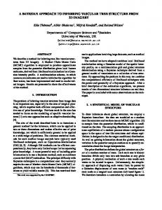
The TD incremental placement problem can be formally stated as follows. Input: A placed circuit PC with some vacant positions both cell movements Initial Placed and deterioration of placement metrics Circuit like total wirelength (WL) and chip area, and (2) either: (a) the critical path dePerform STA & determine critical lay in PC 0 is not increased beyond the node set moveC one in PC (this applies in applications where the target clock speed has been TD analytical met, and the ECO process is used to recplacement (TAN) (on moveC) tify other circuit problems), or (b) the critical path in PC 0 is significantly imTD n/w−flow proved compared to the one in the prebased detailed vious layout–we will focus on this obplacement (TIF) (on moveC) jective in this paper, though our incremental placer can also be used to tackle applications of type 2(a) as well. New Placement w/ improved Fig. 1 shows the flow of our TD inperformance cremental placer used in applications of Figure 1: The type (b) given above. We start from a placed circuit, and identify all critical flowchart of our and near-critical paths using static timTD incremental ing analysis (STA). Let this set of paths placer FlowPlace. be P. After P is identified, we remove either: (i) only the cells in P from the layout, or (ii) all cells in all nets in P from the layout. The removed cells form the cell set moveC (nets connected to cells in moveC are de-
We perform STA to determine delays to the output pins or flip-flops (FFs) of the circuit; each of these “terminal” pins have a max-delay path to them, and the maximum delay over all these paths is the critical path delay. We define a nearcritical path as a max-delay path to a terminal pin whose delay is within a (1 − ) fraction of the critical path delay; we use = 0.1 in our experiments. A path P ’s slack S(P ) is defined as the difference between the required arrival time (RAT) at the terminal pin of P and the arrival time (AT) of P . We assume a single target clock speed and thus uniform RATs at all terminal pins (our methods easily apply to non-uniform RATs as well). For the purpose of meaningful slack-driven cost functions to minimize critical interconnect lengths, we need positive slacks, and we thus bootstrap our methods by defining the RAT of the terminal pin of the critical path as (1 + α) times the critical path delay; we use α = 0.1 in our experiments. This ensures positive slack for all paths, and of course smaller slacks for more critical paths.
3.
TD ANALYTICAL GLOBAL PLACEMENT
Our analytical placer TAN is a TD extension of a combination of Gordian [10] and Gordian-L [13]–we optimize an objective function that contains both linear and quadratic terms.
3.1 Basic Gordian and Gordian-L Gordian [10] is a quadratic programming technique for cell placement for quadratic WL minimization. The quadratic net
length estimate can be based on either a clique or a star-graph model. For the latter (see Fig. 2(a)), which we use in our TD objective function, the quadratic net length of net nj with k pins is given by: X L2 (nj ) = (xi − xc )2 + (yi − yc )2 ui ∈nj
where (xi , yi ) are the coordinates of pin ui , (xc , yc ) is the coordinate P of the centroid of the pins of nj , with xc (yc ) = (1/k) × ui ∈nj xi (yi ). For a circuit netlist G, Gordian performs ud(x d, yd ) up(x p , yp) centroid an optimization of the quadratic objecC(x c , yc ) tive function P uq(x q , yq ) u i(x i , yi ) 2 nj ∈nets(G) L (nj ). (a) The linear constraints u (x i , yi ) (1−γ)of C total include those on the coordinates to be ld,i initially within chip boundaries, and then up(x p, yp) ud(xd , yd) l /2 d,i within boundaries of γ of C total subregions–after each uq(x q , yq) Gordian phase in a region, the cells are (b) partitioned, based on Figure 2: (a) The star-graph model their solution coordinates, into two for net length estimate. (b) Intersubregions by a cutconnect delay computation in a preline perpendicular to routing placement. Ctotal is the total the optimization di(net and load) capacitance seen by the mension (x or y). driver. This prevents cell overlaps among the two groups and ultimately between every subgroup of cells where this hierarchical process ends. Gordian-L [13] applies an additional inner-iteration for the optimization in each subregion, which essentially comprises of dividing in the (m + 1)’th inner iteration, each L2 (nj ) part of the objective function by a net-centric linear-length quantity P m given by ηjm = ui ∈nj |xm i − xc | (for the optimization along the horizontal dimension), where xm i is the value of the xcoordinate of ui after the m’th iteration, and ηi0 = 1. This has the effect of linearizing the objective function at the end of the inner iteration. i
3.2 Net Delays and Objective Function We assume that we start with an unrouted placement 1 , and thus use the routing model shown in Fig. 2(b). For a net nj with driver ud , and k − 1 ≥ 1 sinks, let Rd be the driving resistance, Cg the load capacitance of a sink pin2 , r (c) the unit wire resistance (capacitance), and ld,i the interconnect length connecting driver ud to sink ui ; see Fig. 2(b ). Referring to this figure and considering a sink ui in nj , the delay D(ui , nj ) to it (using the Elmore delay model) from the driver ud , consists of three parts: 1
Our methods apply to routed placements as well. However, since routing consumes a dominant part of the PD phase, it would be beneficial to perform a quick-and-approximate pre-routing estimate of critical path delays using as-accurate-as-possible net route models and performing TD re-placement before proceeding to the actual routing stage. This will hopefully be beneficial for pre-routing corrections thus saving significantly in design times. 2 For simplicity of exposition, we assume uniform loads for all sink pins, though clearly our net-delay modeling and methods also apply to nonuniform loads.
D1 (nj ) = Rd (c · L(nj ) + (k − 1)Cg ) D2 (ui , nj ) =
rc 2 · l + r · ld,i Cg 2 d,i
(1) (2)
D3 (ui , nj ) = r·(ld,i /2)((1−γ +γ/2)(c·L(nj )+(k−2)Cg ) (3) and D(ui , nj ) = D1 (nj ) + D2 (ui , nj ) + D3 (ui , nj )
(4)
where γ ≤ 1, and note that the D1 (nj ) delay component is the same for all sinks of nj . The idea behind the 3rd delay component D3 (ui , nj ) is that without an exact route, we estimate that if ui lies in the initial γ fraction of the HPBB of nj starting from the driver position, then, on the average, half of the interconnect length ld,i lies on the main trunk of the estimated route, and it “sees” the entire wire and sink capacitance of the rest of the (1 − γ) fraction of the net. Furthermore, incremental pieces of this part of the (ud , ui ) interconnect on the main trunk can also see incremental portions of the γ fraction of the net and load capacitance, which ultimately results in this interconnect seeing a γ/2 fraction of the total (load + net) capacitance Ctotal . We define the critical delay Dc (nj ) of nj as: X Dc (nj ) = D1 (nj ) + D2 (ui ) + D3 (ui ). ui ∈critical(nj )
The intent here is to include in Dc only the delays of the set critical(nj ) of sinks of nj lying on near-critical paths. Note that Dc is really a delay-criticality measure of nj rather than an actual delay of some component of this net. We define the allocated slack Sa (nj ) of net nj as S(Pmax (nj ))/(# of nets in path Pmax (nj )), where Pmax (nj ) is the maximum-delay path through nj , and recall that S(P ) is the slack of path P . How much minimization should be performed to reduce a net nj ’s interconnect lengths for optimizing the circuit’s critical path delay depends not only on the net’s Dc value but also on S(Pmax (nj ))–a net with high Dc value but one lying on a path with relatively high slack should have lower delay optimization priority, and similarly for the reverse case. Furthermore, two nets ni , nj on different max-delay paths with similar slacks and similar Dc values, should not necessarily be optimized similarly. The important parameter besides Dc for determining optimization priority is the allocated slack Sa of a net. The rationale for this is as follows. Let the maxdelay path through ni (nj ) have 10 (5) nets in them. If the delay optimization priority were the same for all the nets on Pmax (ni ) and Pmax (nj ) due to their similar Dc and path slack values, then the delays on their critical interconnects (assuming only one critical interconnect from the driver to a single critical sink on each of the 15 nets) will be made almost equal. This results in Pmax (ni ) having twice the delay of Pmax (nj ), and thereby a higher probability of violating the target clock speed. On the other hand, if the delay cost of each net is made ∝ Dc /Sa , then in our example, since the Sa for the nets in Pmax (ni ) are half that of those in Pmax (nj ), the former will have twice the delay optimization priority (i.e., delay cost) than the latter leading to balanced delays for both critical paths Pmax (ni ) and Pmax (nj ). Based on the above arguments we define the delay cost CD (nj ) of nj as CD (nj ) = Dc (nj )/Sa (nj )β where β is an exponent of the Sa metric that allows magnification (with β > 1) or shrinking (with β ≤ 1) of differences in optimization priorities of nets on paths with with varying allocated slacks; we use β = 1 in our experiments.
Row Boundary
C15
C16
W1
Details in (b) Source C21
C22
C23
C24
W21
C25
W2
Row 1
(Σw( W1i ), 0 ) capacity (Σw( W2i ), 0 ) Row 2
(w(A 1 ), 0)
(w(W21), 0)
A1
(w(A 2 ), 0)
C31
C32
C34
C35
(a).
C36
W3
Row 3
White space cells
A1
C12
(w(A 1), c5 ) (w(A 2) , c6) From C22 , C23
From Row 3
Dout Din
C21 (w(C21 ), 0)
To Row 3
(o( A2, C32 ), c8 )
A2 From C21 , C22
(w(C21 ), 0) Din
(Σw( W3i), 0 ) C33
C11
Sink
New Cell A2
Details in (c)
cost
(w(C31 ), 0)
(b)
C31
(o( A1, C32 ), c7 )
C14
(o( A1, C31 ), c6 )
C13
C12
(o( C21 , C12 ), c3 )
C11
(o( C11 , C21 ), c1 )
(max(w), ch )
Din (w(C32 ), 0) C32
(c)
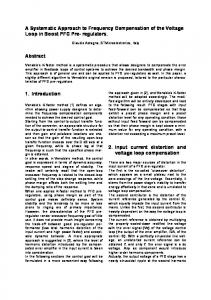
Figure 3:
(a) The high-level network flow graph for placing cells A1 , A2 in legal positions; w(u) is the width of a cell u. (b) Details of flow graph structure for vertical flows between cell pairs (C1,1 , C2,1 ) and (C1,2 , C2,1 ); o(u, v) is the amount of horizontal overlap between cells u and v. This flow graph structure only allows a flow of amount