J Med Syst (2012) 36:437–450 DOI 10.1007/s10916-010-9488-x
ORIGINAL PAPER
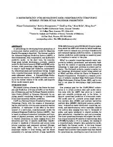
A User-Centered, Object-Oriented Methodology for Developing Health Information Systems: A Clinical Information System (CIS) Example Georgios Konstantinidis & George C. Anastassopoulos & Alexandros S. Karakos & Emmanouil Anagnostou & Vasileios Danielides
Received: 18 January 2010 / Accepted: 5 April 2010 / Published online: 23 April 2010 # Springer Science+Business Media, LLC 2010
Abstract The aim of this study is to present our perspectives on healthcare analysis and design and the lessons learned from our experience with the development of a distributed, object-oriented Clinical Information System (CIS). In order to overcome known issues regarding development, implementation and finally acceptance of a CIS by the physicians we decided to develop a novel object-oriented methodology by integrating usability principles and techniques in a simplified version of a well established software engineering process (SEP), the Unified Process (UP). A multilayer architecture has been defined and implemented with the use of a vendor application framework. Our first experiences from a pilot implementation of our CIS are positive. This G. Konstantinidis (*) : V. Danielides ENT (Ear Nose Throat) Department, Medical School, Democritus University of Thrace, Alexandroupolis, Greece e-mail:
[email protected] V. Danielides e-mail:
[email protected] G. C. Anastassopoulos Medical Informatics Laboratory, Medical School, Democritus University of Thrace, Alexandroupolis, Greece e-mail:
[email protected] A. S. Karakos Department of Electrical and Computer Engineering, Democritus University of Thrace, Xanthi, Greece e-mail:
[email protected] E. Anagnostou ENT (Ear Nose Throat) Department, Nikaia General Hospital, Piraeus, Greece
approach allowed us to gain a socio-technical understanding of the domain and enabled us to identify all the important factors that define both the structure and the behavior of a Health Information System. Keywords User-centered . Object-oriented methodology . UML . Clinical information system . Multi-layer architecture
Introduction The slow acceptance of clinical information systems is somewhat of an anomaly given the rapid diffusion of most other health care technologies [1–4]. This unique phenomenon has thoroughly been studied and three major parameters have been identified: Inability to conceive the health domain unique nature [5–13], software design weaknesses [14–17] and finally inability to win stakeholders’ (physicians, nurses, administrative personnel, management) approval [18–26]. It is more and more acknowledged that a sociological understanding of the complex practices in which information technologies are to function is crucial [27]. The dynamic complexity of health organizations cannot be captured through traditional waterfall (sequential) lifecycle processes. These processes are strongly associated with high rates of failure, lower productivity, and high defect rates. According to Berg’s socio-technical approach, “because of the political nature of these processes and the importance of the user, and because of the fundamentally unpredictable nature of these change processes, an iterative approach to development is required. Starting with central organizational needs, systems have to be developed step by step, so that the changes in technology and work practices
438
can evolve together” [12]. An iterative software engineering process (SEP) can more easily adapt to the needs of a rapidly changing domain, such as healthcare. A SEP is the process in which we turn user requirements into software, a set of project phases, stages, methods, techniques, and practices that people employ to develop and maintain software and its associated artifacts (plans, documents, models, code, test cases, manuals, etc.). The Unified Software Development Process (USDP) [28] is an iterative SEP from the authors of the Unified Modeling Language (UML) [29]. It is commonly referred to as the Unified Process or UP. Rational Unified Process (RUP) is a commercial version of UP [30]. Both standard UML and standard UP or RUP can be very complex and can drive a project to analysis paralysis. UML describes thirteen different types of diagrams while UP and RUP suggest a huge number of activities and artifacts. Hansen G. K. et al present a review and a systematic assembly of existing studies on tailoring and introduction of RUP [31]. According to their study, RUP is out of the box too complex; tailoring it to specific needs is also too complex. Only few or none (reported) success stories exist. Moreover, there are known issues regarding proper requirements eliciting and usability of Health Information Systems. UP (requirements workflow), defines specific tasks such as “Find actors and use cases”, “Prioritize use cases”, “Detail a use case” or “Structure the use case model” but does not specify methods for finding functional and non-functional requirements, prioritizing requirements or tracing requirements to use cases. Research, outside healthcare domain, investigating the integration of usability activities into a software development process [32–35] perceived usability as being a function of the interface and did not mention the impact of software architecture in developing usable systems. John and her colleagues [36], in a comparison of the ISO 13407 Human-centered design processes for interactive systems [37] to the Rational Unified Process (RUP) indicate that best practices for software development teams emphasize the fact that the RUP is considered architecture-centric and does not adequately take into account user concerns, while ISO 13407 does not consider the role of software architecture in fulfilling usability requirements. In our opinion, neither RUP nor ISO 13407 can effectively describe and implement a robust and usable Healthcare Information System (HCIS). A novel approach combining the object-oriented nature of RUP with the user-centric character of ISO 13407 is needed for this purpose. In this paper, we illustrate how we overcame the issue of complexity during the development of a CIS, by introducing a more laconic approach that uses a minimal, yet sufficient core subset of UML (four diagram types) with the addition of robustness diagrams (borrowed by the ICONIX
J Med Syst (2012) 36:437–450
process [38]), as well as a limited number of activities and artifacts, compared to standard UP or RUP. In addition, we present usability techniques integrated in our SEP that cover the whole project lifecycle and improve user acceptance. We also present the multilayer architecture of the ENTity CIS. This is an ENT (Ear, Nose and Throat) CIS, built with our SEP, to cover the needs of a Greek General Hospital ENT Department.
Methods The unified process In accordance with UP we divided our project life cycle into four phases—Inception (life cycle objectives), Elaboration (life cycle architecture), Construction (initial operational capability) and Transition (product release)—each of which ended with a major milestone. Within each phase we have had one or more iterations, and in each iteration we have executed the five core workflows. The five core workflows are: Requirements—capturing what the system should do, Analysis—refining and structuring the requirements, Designing—realizing the requirements in system architecture, Implementation—building the software, and Test—verifying that the implementation works as desired. Each phase ended with a milestone that consisted of a set of conditions of satisfaction, and these conditions involved the creation of a particular deliverable. We chose a very simple format for stating requirements elicited from our fact-finding techniques. Each requirement has a unique identifier (a number), a subject (The system), a keyword (shall), and a statement of function. < id > The < system > shall < function > Figure 1 shows the metamodel for our approach to requirements engineering in this project. We chose to categorize our requirements according to the FURPS + system, a useful mnemonic with the following meaning: Functional—features, capabilities, security, Usability—Human factors, help, documentation, Reliability—frequency of failure, recoverability, predictability, Performance—response times, throughput, accuracy, availability, resource usage, Supportability—adaptability, maintainability, internationalization. The “+” in FURPS + indicates ancillary and sub-factors, such as: Implementation— resource limitations, language and tools, hardware, Interface— constraints imposed by interfacing with external systems, Operations—system management in its operational setting, Packaging, Legal—licensing and so forth. We decided that each requirement should have a set of attributes that captures extra information (metadata) about the requirement. These
J Med Syst (2012) 36:437–450
439
Fig. 1 Requirements metamodel for the ENTity project
attributes are: Priority—We chose here to follow the MoSCoW criteria according to which the priority attribute can take one of the values M (must have), S (should have), C (Could have) or W (want to have), Source—An attribute that specifies the origin of the requirement (staff member) and Status—An attribute indicating the status of the requirement. However, UP is an extensible framework that comprises far more activities than any person or organization requires. For this reason, this generic process had to be customized in order to adjust to the needs of a specific project, such as a clinical information system. We chose to use 4 out of the 13 diagrams offered by UML and produce only a subset of the artifacts proposed by the UP class diagrams to describe the static model and use case diagrams, robustness diagrams, sequence diagrams and state machine diagrams to describe the dynamic model. During use case analysis we followed a concrete use case style from the very beginning of the project. In this style, user interface decisions, as presented by GUI storyboards and realistic prototypes, are embedded in the use case text. We tried to present not only what the actors need the system to do, but also how the system should do it, in relation to the User Interface (UI) provided by the UI prototypes. This practice comes in contrast with the essential writing style proposed by several writers including Constantine [39] where the narrative is expressed at the level of the user’s intentions and system’s responsibilities rather than their concrete actions. However, we found that the use of a concrete use case style saved us a lot of
valuable time and made easier the transition from requirements to design and code, preventing “analysis paralysis”. We used a direct 1:1:1 correlation between the steps described in the use case text, the flow of action in the robustness diagram and the flow of action in the sequence diagram. In fact, robustness diagrams do not belong to the set of diagrams offered by UML. They were first described by Doug Rosenberg and Kendall Scott [40] and they were later used as part of the ICONIX process [38]. A robustness diagram is somewhat of a hybrid between a class diagram and an activity diagram, a pictorial representation of the behavior described by a use case, showing both participating classes and software behavior, although it intentionally avoids showing which class is responsible for which bits of behavior. In a way it connects the dynamic with the static model, it bridges the gap between analysis and design. Sequence diagrams show in a more detailed way how the classes will interact with each other. We tried to make them precise so that a detailed design that works within the technical architecture we defined can be derived. Class diagrams show the system’s classes, their attributes and the relationships between the classes. State diagrams describe a sequence of states and the state changes of a class. They display processes that refer to the lifecycle of a class instance. For this reason, state diagrams are always bound to a class. In Fig. 2, we see a graphic representation of the Development Case for the Entity project. This figure uses as background the figure adopted from Jacobson et al [28]
440
J Med Syst (2012) 36:437–450
Fig. 2 Graphical representation of the Development Case for the ENTity project
representing the five core workflows that take place over the four UP phases. The Development Case is a UP artifact itself and a description of the customized UP steps and artifacts for our project. Along the top we have the phases of the UP while down, on the left-hand side, we have the five core workflows. Along the bottom we have some iterations. The curves show the relative amount of work done in each of the five core workflows as the project progresses through the phases. The blue round rectangles show the models, diagrams, methods and UP artifacts produced during the project lifecycle and their estimated duration.
before we even visited the hospital and conducted the initial field studies. We defined a set of criteria that would help us evaluate each software product. Those evaluation criteria were aesthetic appeal, forms, help, usability and accessibility and time-speed. As we were conducting the competitive analysis we created a grid comparing the “competitors’” products according to our evaluation criteria. This grid also contained features that were identified and could be implemented within our Clinical Information System as well as the specifications of each software product. We can see a detail from this grid in Table 1.
Usability methods One of our main goals during the development of the ENTity CIS was to incorporate usability principles into the product lifecycle. This was accomplished by employing techniques, processes and methods that focus on the potential user. Before each activity we created an activity proposal and an activity protocol asking users to sign a confidentiality agreement and a consent form. In Fig. 3, we see the usability methods incorporated into the ENTity CIS in relation with the phases of the project lifecycle. Usability competitive analysis A usability competitive analysis proved to be an excellent shortcut that quickly provided us with a range of viable design solutions (organizational schemes, labeling, forms layout, functionality and content) and potential features
Fig. 3 Usability Methods incorporated into the ENTity CIS in relation with the phases of the project lifecycle
J Med Syst (2012) 36:437–450
441
Table 1 Detail from the grid created during usability competitive analysis Company A Aesthetic appeal Overall visual organisation 7 Balance 6 Color scheme 5 Contrast 9 Imagery 5 Design identity 5 Forms Layout Consistency 7 Organisation 10 Balance 7 Presentation 5 Functionality 10 Help/Instruction Quantity of help options 7 Embedded help options 8 Display 6 Organisation 6 Quality 9 Presentation 6 Usability and accessibility Visibility of system status 5 Match between the system 5 and the real world User control and freedom 5 (support of undo and redo) Consistency and standards 6 Error prevention 6 Recognition rather than recall 9 Flexibility and efficiency 8 of use 6 Help users recognise, diagnose and recover from errors Time (Speed, up to date information) Speed 15 Up to date information 17 Overall 200 Specification Operating system-server No server Operating system-client Architecture Programming language Database Core Features: Historical record keeping Bed availability estimation Operative reports
Company B
Company C
Company D
Company E
Company F
9 8 8 9 5 5
14 15 13 14 12 15
13 14 14 15 16 18
20 18 19 20 21 18
22 20 21 23 20 22
7 11 8 7 10
13 17 16 15 14
16 16 15 16 16
16 18 19 18 18
20 20 22 20 21
8 8 7 6 8 6
17 18 15 14 14 15
18 18 16 15 16 14
20 21 20 18 19 20
22 23 23 22 19 23
5 6
12 11
14 11
20 17
21 16
5
5
14
21
21
5 7 12 8
9 12 14 15
12 11 16 12
16 17 13 18
22 23 20 21
7
12
12
17
23
17 18
15 18
20 20
22 21
24 22
220
251
408
505
579
No sever
Windows Sever 2003 or newer Windows OS Client-Server Delphi 2007
Windows Server 2003 or newer Windows OS Client-Server Visual Basic
Windows Server 2003 or newer Any OS multi-tier C#
Interbase
MS SQL Server
MS SQL Server
Windows Server 2003 or newer Any OS multi-tier Visual BasicVisual C++ Oracle SQL Server
+ − +
+ + +
+ + +
Windows OS Client only MS ACCESS 97/2003 MS ACCESS 97/2003
Windows OS Client only MS ACCESS 97/2003 MS ACCESS 97/2003
+ − −
+ − −
+ + +
442
J Med Syst (2012) 36:437–450
Table 1 (continued)
Operation’s booking Vital signs recording Nursing flowsheet Patients admissions Patient inflow, waiting time, crowding Seek out specific information from patient records Keep the results from new test or investigations
Company A
Company B
Company C
Company D
Company E
Company F
− + − + −
− + − + −
− + − + −
− + + + −
+ + + + −
+ + + + +
+
+
+
+
+
+
+
+
+
+
+
+
Deep hanging-out analysis A technique we used during the first iterations of the inception phase in order to elicit our project’s requirements is a field study method called Deep Hanging-Out Analysis. This is based on an observation only approach that provides structure by suggesting focus areas and things to observe. Researchers from Intel developed this method by applying anthropological techniques to field research [41]. The ten focus areas we
decided to study for our project were those originally proposed by the developers of this method: family and kids, food and drinks, built environment, possessions, media consumption, tools and technology, demographics, traffic, information and communication access, and overall experience. Data was collected at different times in a day and during different days of a week. Observation initiated from the very beginning of the process and maps describing the environment of our users were created. In Fig. 4, for
Fig. 4 Map of the inpatient clinic created during Deep Hanging-Out Analysis
J Med Syst (2012) 36:437–450
example, we see a map of the inpatient clinic created during Deep Hanging-Out Analysis. Various artifacts (objects, items or papers users use to complete their task or produced as a result of their tasks) were collected during the time of observation. Potential hazards, dangers and obstacles during the execution of a task were recognized. Several photos and videos were also taken. For each focus area the responsible team member handed on a report which was revisited and further elaborated through the Inception and Elaboration phases of the project. Several of the focus areas we selected are rarely studied and usually neglected during HCIS analysis. However, we cannot stress enough their importance for identifying requirements, often “hidden” among core healthcare processes, but critical for the success of the project. For example, in our ENT CIS project, the study of the “family and kids” sector revealed a major security requirement, not initially identified during process analysis. In this case, the lack of nurse personnel, which is an important parameter that characterizes the Greek healthcare system in general (only one nurse for 20 beds during the night shift, for the Department where the study took place) required a third person, not a member of the staff (usually a patient’s relative), to spend the night near the patient’s bed. This person had to be recorded and provided with a security clearance by the system, for the period of time the specific patient was hospitalized. Process analysis (PA) Process Analysis is another field method for identifying processes. Here, unlike Deep Hanging-out Analysis, interaction with the user plays an important role. The enquirer visits the user environment in order to understand the context of his/her actions. A master-apprentice relationship with the user is developed and results are interpreted with the participant in order to be used later. Focus is given on identifying processes. For this purpose, the participant is asked to answer a series of predefined questions when a certain process is identified (e.g. When does the first task in the process happen? What triggers it? etc.). Processes recognized during Process Analysis were marked on site maps created during the Deep Hanging-Out analysis. Data from PA helped us create user profiles and scenarios. User profiles were also added to the site maps and processes were attributed to the user profile that was responsible to execute them. User profiles evolved to use case actors while scenarios were further detailed and structured to produce use case scenarios. In Fig. 5, we see processes executed by a specific user profile in an office of the inpatient clinic. A detail (doctors’ office) from the map in Fig. 4 has been used.
443
GUI storyboards and realistic prototypes GUI storyboards were produced from the very beginning of the project and evolved to realistic prototypes. Prototypes proved to be an excellent method in early stages of development to evaluate the first user interface designs and validate the usability of the system. They were substituted later in our testing process (usability tests and heuristic evaluations) by early editions of the final system. Usability tests Usability tests were conducted during Iteration 4, Iteration 8 and Iteration 12. Five end users took part in each usability test. Representative tasks, deriving from scenarios and use cases developed earlier in the design process, were combined in order to build 10 real life test scenarios. Every scenario included processes identified in many different settings of the ENT department and the hospital e.g. the operating room, the ambulatory, inpatient and outpatient clinics, in order to validate the system’s robustness to handle different operations. This list of scenarios came together with criteria for measuring whether the tasks have been successfully completed. Recording of timing, events, participant actions, concerns and comments has been done through logging sheets filled in by the participants at the end of each scenario. Metrics such as the percentage of participants who succeeded at each scenario, the average time to complete each scenario, and the average number of screens visited in each scenario were calculated. A postevaluation questionnaire based on the USE Questionnaire (1 to 7 rating scale) [42] was used to measure usefulness, ease of learning, ease of use and user satisfaction and to provide any additional information participants wanted to share. Heuristic evaluations Heuristic evaluations were conducted during Iteration 6, Iteration 10 and Iteration 14. Heuristic evaluation is a method for finding usability problems in a user interface design so that they can be attended to as part of an iterative design process. A small team of 3 evaluators with experience in software development examined the interface several times, inspected the various dialog elements and judged their compliance with a list of 13 recognized usability principles (the “heuristics”). These heuristics are: visibility of system status, match between the system and the real world, user control and freedom, consistency and standards, help users recognize, diagnose and recover from errors, error prevention, recognition rather than recall, flexibility and efficiency of use,
444
J Med Syst (2012) 36:437–450
Fig. 5 Processes executed from a specific user profile in an office of the inpatient clinic
aesthetic and minimalist design, help and documentation, skills, pleasurable and respectful interaction with the user, and privacy. For every heuristic evaluation we used a different team of evaluators, with no previous involvement with the project, in order to avoid contamination of our results due to user learning. A system checklist was employed in order to simplify the team’s work. In addition to the checklist of general heuristics to be considered for all dialog elements, each evaluator was also allowed to consider any additional usability principles or results that could potentially be related to any specific dialog element. Severity ratings were collected by means of a questionnaire sent to the evaluators after the actual evaluation sessions, listing the complete set of usability problems that have been discovered, and asking them to rate the severity of each problem. The following 0 to 4 rating scale was used to rate the severity of usability problems: 0 = I don’t agree that this is a usability problem at all 1 = Cosmetic problem only: need not be fixed unless extra time is available on project 2 = Minor usability problem: fixing this should be given low priority 3 = Major usability problem: important to fix, so should be given high priority 4 = Usability catastrophe: imperative to fix this before product can be released The mean of ratings from the 3 evaluators was calculated for each heuristic.
Results System architecture In our project implementation we decided the logical separation of our application into 5 distinct layers as seen in Fig. 6. Presentation layer The purpose of this layer is to present information, record input from the user or receive other instructions such as updating the data storage, navigating to other data, executing reports, etc. We chose a thin-client approach. So, UI objects only initialize UI elements, receive UI events (such as a mouse click on a button), and delegate requests for application logic on to non-UI objects (application layer objects). We chose to implement this layer as a .NET application executed on Win32 platform, but the clear separation of concerns (user interface, application logic, business logic, data access logic and persistence, each on a different layer) makes it less work to implement a second or third presentation layer. Application layer The purpose of this layer is handling presentation layer requests through communication with the data access layer and providing security mechanisms (Confidentiality, Integrity, Authentication, and Authorization). This includes presentation layer requests acceptance, transmission of the
J Med Syst (2012) 36:437–450
445
Fig. 6 Architecture of ENTity CIS
request to the data access layer, consolidation/transformation of disparate data imported from the data access layer for presentation, workflow management, session state management etc. The fact that the application layer is implemented as an ASP.NET XML Web service hosted on an IIS (Internet Information Service) Server allows invoking properties and methods of remote objects using standard HTTP requests. HTTP is a wire protocol that all platforms can agree on. A .NET client application running on Windows, a Java client application running on UNIX, a Java or .NET client application running on Macintosh or a client application running on Windows Mobile can easily use the web service through an intervening proxy type. The proxy’s implementation code forwards requests to the XML web service using standard HTTP. The proxy also maps the incoming stream of XML back to the specific data types required by the consumer application. System security is safeguarded through IIS built-in security mechanisms (encryption through signing with SSL—Secure Socket Layer, mutual authentication over SSL, code access security).
Business layer The purpose of this layer is to reflect as accurately as possible the entities of the business the application is being designed to emulate (the “Business domain”). These class entities not only contain properties for holding information about the business objects, but also methods which are being executed in order to reflect the behavior of these entities, as well as domain rules. This layer is implemented through the use of a vendor application framework, called ECO framework [43]. ECO uses class diagrams and state machines to describe the static and dynamic structure of the domain. Diagrams are permanently synchronized with code automatically generated by the tool. Queries to the data access layer and domain rules are written in ECO OCL and object handling methods in ECO Action Language. The Object Constraint Language (OCL) [44] was added as an extension to the UML-Specification in 1997 by the Object Management Group (OMG). OCL is supported by ECO both at development stage and runtime. It is a query language free of side effects that doesn’t
446
access the database directly. Instead, it simply accesses objects located in an object manager in the central memory called EcoSpace. If an object is not available in the EcoSpace, it will be loaded on demand when needed. Moreover constraints which limit the contents or semantics of UML model elements can be defined with the use of OCL. ECO also uses ECO Action Language (EAL). EAL is a superset of OCL. It contains all features and operations of OCL plus an assign operation, list-manipulation operations, object creation/deletion and sequencing of statements. It is primarily used to define effects inside state machines, but it can also be used as a general purpose scripting language. Data access layer The data access layer is the functional crossroad between the application layer, the business layer and the persistence storage. This layer is also implemented with the ECO Framework through the use of EcoSpaces that reflect to object packages. The data access layer will retrieve data from the specified data storage and transform this data into an instance of the relevant class from the business layer, which will present to the application layer. In addition, it is responsible for updating the data storage with changes made to business class instances, and also to delete data from the persistence storage, where business class instances have been permanently destroyed. In this layer the complete runtime management of objects (Catching, Pooling, Synchronization, Transactions, OCL Evaluation etc) takes place. Persistent storage layer The persistent storage is responsible for persisting, retrieving, and deleting permanently stored data as instructed by the data access layer. A persistence mapping system offered by ECO automatically maps the class model on a relational database, thus taking care of the fully automatic creation and updating of the database schema. At runtime, the persistence mapping system takes care of the transformation of relational data to class model objects in EcoSpace and back into the database tables. Persistence storage independence is offered through the use of persistencemapper components for most popular database systems (Interbase 2007 and later, Oracle v8 and later, MSSQL server 2000 and later including express editions, MySQL v4 and later, Firebird v1.5 and later, NexusDB v2, SQLite and Sybase ASE). This way, ECO almost fully takes over the task of database design based on the class model. The system administrator can easily switch between different persistence stores or determine which type of data storage to use at runtime according to the user’s application settings. Moreover objects can be loaded and saved across
J Med Syst (2012) 36:437–450
multiple persistence stores. Mixed database servers or distributed transactions are also supported. Implementation-first experiences The study was performed in the settings of inpatient and outpatient ENT clinics of Nikaia General Hospital, a hospital with 713 beds and an important regional function. The ENT Department encompasses one inpatient ward with a total of 20 beds and provides many outpatient clinics both routine and specialist (Rhinology-Endoscopy Clinic, Otology-Neurootology Clinic, Cochlear Implantation Clinic, Facial Nerve Clinic, Otosurgery Clinic, Voice and Swallowing Clinic). For the year 2007, 30208 patients were examined in the ENT outpatient clinics, 1030 patient were admitted and 1419 operations were performed. There is a team of 1 secretary, 8 nurses, 9 residents, and 6 consultants. This team collaborates with many ancillary departments, other specialists and paramedical personnel. An Excel file consisting patients’ id, last name, first name, age, date of admission and diagnosis was created by the physicians in the year 2003. This data gave the physicians the ability to locate based on the patient id the hard copies of the admitted patient’s health record. The hospital despite its size retains no Hospital Information System and none of the departments of the hospital kept an electronic medical record. In 2007, Democritus University of Thrace and the ENT Department of Nikaia General Hospital decided to collaborate in order to produce a pilot ENT Clinical Information System, the ENTity CIS. The project lifecycle was divided into 16 3-week iterations (with the exception of the first iteration that lasted 4 weeks). The project’s duration was 354 days and the work put into it 6922 hours. 5 people worked in the project sharing the roles of project manager, analyst, designer and programmer. Deep user involvement from the very beginning to the end of the project, assisted user learning, improved user understanding of the system and increased user efficacy in completing important tasks and scenarios. All usability metrics calculated improved as the project evolved. User satisfaction also improved (Fig. 7). Moreover, multiple heuristic evaluations proved an increase of the system overall usability through time (Fig. 8). In January 2009, the development team and the physicians decided to proceed with a pilot implementation of the ENTity CIS in the inpatient clinic and in two of the outpatient clinics (Voice and Swallowing clinic, Otosurgery clinic). Currently the ENTity CIS contains all desired functionality. The pilot approach was chosen though, because we wanted to trial the new system over a period of time before all clinics come on board later on, when the system has been proven and the users are
J Med Syst (2012) 36:437–450
447
Fig. 7 Usability and user satisfaction metrics produced during usability testing
confident in its abilities and performance. Currently 5500 inpatient records dated from 2003 are being transferred from paper to the ENTity CIS, while every new record originating from the selected clinics is being recorded electronically. Adoption was not an issue and no particular training was necessary since all users were actively involved in the project from the early stages of development. A two-days training program was prepared for every new member of the department. The trainer is always a current member of the team. Particularly encouraging is a general sense of excitement from the first days of implementation when talking to active users. Curiosity and interest was also expressed from personnel coming from different departments of the hospital.
Discussion For the development of the ENTity CIS we created a usercentered, object-oriented methodology based on a successful open standard (UP). ISO 13407 provides guidance on achieving quality in use by incorporating user-centered
design activities throughout the life cycle of software systems, but it does not address in detail, the level of effort required or the process of selecting the proper activities for a specific project. Moreover, it is not connected to a software design environment or a development process, and it does not provide any implementation or testing phases and activities. The proposed, in this paper, approach in software design, has several additional advantages compared to ISO 13407 because of the adoption of an objectoriented software development process in its core. This process enabled us to standardize our efforts, promoting reuse, repeatability, and consistency between the members of our project team. It made easier the assignment of roles and responsibilities and raised the communication level between developers and end users. Even people that could not read code were able to understand what developers were doing through architectural documents. Second, it provided an opportunity for us to introduce industry best practices such as code inspections, enterprise patterns, configuration management, change control, architectural modeling and test plans to our software organization. Third, a baseline approach for greater consistency and future enhancements was established.
448
J Med Syst (2012) 36:437–450
Fig. 8 Usability issues found during heuristic evaluation and mean of severity ratings for each heuristic calculated from 3 Evaluators
An effective software process also improved our organization’s maintenance and support efforts—also referred to as production efforts—in several ways. First, it defined how to manage change and appropriately allocate maintenance changes to future releases of our software, streamlining our change process. Second, it defined both how to transition software into operations smoothly and how these operations are actually performed. Third, our project could be scheduled and cost estimated with sufficient accuracy in order to meet our expectations. UP or RUP is a SEP that has significantly contributed to the software development practice. However, from a usability point of view, it does not provide the support needed to produce a usable system and problems with the use of the process have been observed in several projects [45]. In our effort to overcome this weakness, we have integrated user-centered design principles into our UPbased, object-oriented process. This integration offered us a deeper understanding of the social, financial and psycho-
logical factors affecting the implementation and use of an electronic patient record. User requirements were better defined, false starts and late changes were prevented, more relevant functionality was achieved and more and better ideas were conceived. Deeper user involvement and testing was an assurance that our framework is efficient, effective and in general terms suitable for the intended purpose. Early use of prototypes made the transition easier and accelerated full and smooth integration of the product into the daily practice. Users knew from the beginning what to expect and felt that their ideas and suggestions are taken into account. Personal involvement raised the team morale and optimized user acceptance. Cross-departmental communication and teamwork formed a common understanding between users and the development team. However, we did encounter some problems while employing usability techniques. The amount of data generated was huge. Filtering, evaluating and translating this data to design was time and personnel consuming. Tension was sometimes
J Med Syst (2012) 36:437–450
inevitable since 5 members from the development team and 15 users had to work together almost every day for a long period of time, communicate effectively and respect each other’s contribution and expertise. It was particularly hard finding and isolating contributions characterized by lack of motivation and attention, intimidation, lack of reliability, false assumptions, incomplete knowledge, faulty memory, and domination of conversation or misinterpretation. All these are factors that can contaminate results if not detected early enough through testing and multiple evaluations. The use of an application framework (ECO) in the core of our architecture felt as the natural way of implementing a project under an object-oriented SEP, added a lot out-ofthe-box functionality and saved us a lot of time during development, updating and especially debugging and testing. The fact that we were able to produce from the very beginning of the project executable models ensured that the automatically generated code (almost 70% of our implementation code) conformed to our architectural/design patterns and coding guidelines. There was of course a dedicated test team, extensively unit testing our code and issuing reports with the bugs fixed in each code generation phase. However, most of the bugs had been cleaned up in the models themselves and these bug fixes essentially rippled throughout all the generated code. In fact, when the analysis team discovered how quickly they could change something in the model and get running code, they began asking for more and more changes. We went through several code generation phases before the final one and in the end we delivered a significant number of bug-free lines of functional code. In addition, the proposed clear separation of layers allows multiple areas of the presentation layer to adhere to the same business rules, and makes it less work to implement different presentation layers. This makes ENTity CIS a distributed system with operating system, platform, language and database interoperability and independence which was a major non-functional requirement from the beginning of the project. There is an important limitation though; ECO which lies in the core of ENTity CIS is a .NET application. It requires the presence of the .NET Framework on the server side; it runs on an IIS Web Server and takes advantage of the ASP.NET Web Services at communication level (application layer). No other Server (e.g. APACHE Server) or Web Service (e.g. Java Web Service) can be used. The previously described approach for the development of the ENTity CIS allowed us to gain a socio-technical understanding of the domain and enabled us to identify all the important factors that define both the structure and the behavior of a clinical information system. In addition, we created a usable, applicable framework and we propose a software development process that can be used as a basis for the creation of other Health Information Systems or
449
Software Systems outside healthcare domain, particularly when deep user involvement is of paramount importance for the success of the project.
References 1. Collen, M. F., A history of medical informatics in the United States, 1950 to 1990: Am. Med. Informatics Assoc., 1995. 2. Laudon, K. C., and Laudon, J. P., Management information systems. New approaches to organization and technology. Macmillan, New York, 1998. 3. Wyatt, J. C., Clinical data systems, Part 3: Development and evaluation. Lancet 344(8938):1682–1688, 1994. 4. Reddy, M., et al., Sociotechnical requirements analysis for clinical systems. Meth. Inf. Med. 42(4):437–444, 2003. 5. Berg, M., Medical work and the computer-based patient record: a sociological perspective. Meth. Inf. Med. 37(3):294–301, 1998. 6. Berg, M., and Bowker, G., The multiple bodies of the medical work: Toward a sociology of an artifact. Sociol. Q. 38(3):513–537, 1999. 7. Berg, M., and Goorman, E., The contextual nature of medical information. Int. J. Med. Inform. 56(1–3):51–60, 1999. 8. Atkinson, P., and Heath, C., Medical work: realities and routines. Gower, Farnborough, 1981. 9. Anderson, J. G., and Jay, S. J., Computers and clinical judgment: The role of physician networks. Soc. Sci. Med. 20(10):969–979, 1985. 10. Anderson, J. G., et al., Physician communication networks and the adoption and utilization of computer applications in medicine. . Use and impact of computers in clinical medicine, ed. J.G. Anderson and S.J. Jay, New York: Springer-Verlag, 1987 11. Berg, M., et al., Considerations for sociotechnical design: Experiences with an electronic patient record in a clinical context. Int. J. Med. Inform. 52(1–3):243–251, 1998. 12. Berg, M., Patient care information systems and health care work: A sociotechnical approach. Int. J. Med. Inform. 55(2):87–101, 1999. 13. Berg, M., Implementing information systems in health care organizations: Myths and challenges. Int. J. Med. Inform. 64(2– 3):143–156, 2001. 14. Anderson, J. G., Computer-based ambulatory information systems: Recent developments. J. Ambul. Care Manage. 23(2):53– 63, 2000. 15. Brooke, C., and Maguire, S., Systems development: A restrictive practice? Int. J. Inform. Manag. 18:165–180, 1998. 16. Atkinson, C. J., and Peel, V. J., Transforming a hospital through growing, not building, an electronic patient record system. Meth. Inf. Med. 37(3):285–293, 1998. 17. Hughes, D., WHen nurse knows best: Some aspects of nurse– doctor interaction in a casualty department. Sociol. Health Illn. 10:1–22, 1988. 18. Kaplan, B., Evaluating informatics applications-some alternative approaches: Theory, social interactionism, and call for methodological pluralism. Int. J. Med. Inform. 64(1):39–56, 2001. 19. Laerum, H., Ellingesen, G., and Faxvaag, A., Doctor’s use of electronic medical records systems in hospitals: Cross sectional service. BMJ 323(7325):1344–1348, 2001. 20. Mikulich, V. J., et al., Implementation of clinical guidelines through an electronic medical record: Physician usage, satisfaction and assessment. Int. J. Med. Inform. 63(3):169–178, 2001. 21. Levitt, J. I., Why physicians continue to reject the computerized medical record. Minn. Med. 77(8):17–21, 1994. 22. Cork, R. D., Detmer, W. M., and Friedman, C. P., Development and initial validation of an instrument to measure physicians’ use of, knowledge about, and attitudes toward computers. J. Am. Med. Inform. Assoc. 5(2):164–176, 1998.
450 23. Scarpa, R., Smeltzer, S. C., and Jasion, B., Attitudes of nurses toward computerization: A replication. Comput. Nurs. 10(2):72– 80, 1992. 24. Anderson, J. G., Clearing the way for physicians’ use of clinical information systems. Commun. ACM 40(8):83–90, 1997. 25. Goorman, E., and Berg, M., Modelling nursing activities: electronic patient records and their discontent. Yearbook of Medical Informatics, 2002. 26. Bahensky, J. A., et al., HIT Implementation in critical access hospitals: Extent of implementation and business strategies supporting IT use. J. Med. Syst., 2009. 27. Rahimi, B., Vimarlund, V., and Timpka, T., Health information system implementation: A qualitative meta-analysis. J. Med. Syst. 33(5):359–368, 2009. 28. Jacobson, I., Booch, G., and Roombauch, J., The unified software development process. Addison Wesley, Massachusetts, 1999. 29. Rumbaugh, J., Jacobson, I., and Booch, G., The unified modeling language reference manual: Addison–Wesley, 2004. 30. Kruchten, P., The rational unified process: an introduction, 3rd edition. Addison Wesley, Massachusetts, 2003. 31. Hanssen, G. K., Bjornson, F.O., and Westerheim, H., Tailoring and introduction of the rational unified process in Software Process Improvement, Springer: Berlin / Heidelberg. 7–18, 2007. 32. Krutchen, P., Ahlqvist, S., and Bylund, S., User interface design in the rational unified process. Object modeling and user interface design. Addison Wesley, Boston, 2001. 33. Constantine, L., Biddle, R., and Noble, J., Usage-centered design and software engineering: models for integration, in International Conference on Software Engineering (ICSE). 106–113, 2003. 34. Ferre, X., Integration of usability techniques into the software development process, in International Conference on Software Engineering: Portland. 28–35, 2003.
J Med Syst (2012) 36:437–450 35. Sousa, K., and Furtago, E., RUPi-A Unified Process that integrates human-computer interaction and software engineering, in International Conference on Software Engineering (ICSE). 41– 48, 2003. 36. John, B. E., Bass, L., and Adams, R. J., Communication across the HCI/SE divide: ISO 13407 and the Rational Unified Process, in 10th International Conference on HCI: Crete, Greece, 2003. 37. ISO 13407:1999 Human-centred design processes for interactive systems. 38. Rosenberg, D., and Stephens, M., Use case driven object modelling with UML: theory and practice. Apress, Berkeley, 2007. 39. Constantine, L., and Lockwood, L., Software for use: a practical guide to the models and methods of usage-centered design. Addison Wesley, Massachusetts, 1999. 40. Rosenberg, D., and Scott, K., Use case driven object modelling with UML: a practical approach. Addison Wesley, Massachusetts, 1999. 41. Teague, R., and G. Bell., Getting out of the box: ethnography meets real life: applying anthropological techniques to experience research. in Usability Professionals’ Association 2001 Conference. Las Vegas, 2001. 42. Lund, A. M., Measuring usability with the USE questionnaire. Usability interface. 8(2), 2001. 43. Schmid, A., ECO III, http://www.ecospace.de/en_ecobook.html, 2006, last visited on March 03, 2010. 44. Warmer, J., and Kleppe, A., The object constraint language: getting your modelw ready for MDA. Addison Wesley, Massachussets, 2003. 45. Gulliksen, J., Göransson, B., and Lif, M., A user-centered approach to object-oriented user interface design. In: Van Harmelen, M., (Ed.), Designing Interactive Systems: Object Modeling and User Interface Design. Addison-Wesley, 2001.