A User-Programmable Vertex Engine Erik Lindholm
Mark J Kilgard
[email protected]
[email protected]
Henry Moreton
[email protected]
NVIDIA Corporation
ABSTRACT
performance has driven, and been driven by increasingly rich graphics APIs. The motivation behind the creation of the userprogrammable geometry engine described in this paper is two fold: first, the increasing configurability required by continually evolving graphics APIs requires a programmable device to support the combinatorial explosion of mode combinations. Second, high-performance programmability is an end unto itself. Given the right programming model, with a sufficient degree of target processor independence, the need for rapidly evolving graphics APIs is reduced, and an opportunity is created for inventiveness unconstrained by fixed-function, modally configured APIs and hardware. Further, compatibility across hardware generations and platforms will increase the lifespan and utility of programs written for geometry processors.
In this paper we describe the design, programming interface, and implementation of a very efficient user-programmable vertex engine. The vertex engine of NVIDIA’s GeForce3 GPU evolved from a highly tuned fixed-function pipeline requiring considerable knowledge to program. Programs operate only on a stream of independent vertices traversing the pipe. Embedded in the broader fixed function pipeline, our approach preserves parallelism sacrificed by previous approaches. The programmer is presented with a straightforward programming model, which is supported by transparent multi-threading and bypassing to preserve parallelism and performance. In the remainder of the paper we discuss the motivation behind our design and contrast it with previous work. We present the programming model, the instruction set selection process, and details of the hardware implementation. Finally, we discuss important API design issues encountered when creating an interface to such a device. We close with thoughts about the future of programmable graphics devices.
The programming model and design of the geometry engine in the GeForce3 was guided by several factors: commodity pricing, design time, area, legacy performance, programmable performance, programmability, and platform independence. Ultimately, all of these influence the commercial viability of the design. Design time obviously determines time to market. Area is directly linked to product cost. Previously existing applications must exhibit higher performance on new products. There can only be a slight performance penalty paid for taking advantage of programmability. To gain acceptance, the engine must be easy to program. Finally, to promote adoption across vendors, a standard interface is required and thus the functionality cannot be too tightly coupled to a specific hardware implementation; for example, CPU implementations must be viable.
Keywords Graphics Hardware, Graphics Systems.
1
INTRODUCTION
Geometry
vertex
Host Interface
We provide a taxonomic description of previous programmable graphics processors, comparing them to our device. We show how the programming model can be effectively supported by a custom processor design. We describe how a programmable processing element can be incorporated into an existing graphics API. Finally, we illustrate how the programming model and interface may be used to efficiently implement complex custom effects.
Raster/Texture Framebuffer Interface
fragment
Prim itive Assembly/Setup
2
PREVIOUS WORK
Geometric calculations have been accelerated for over 30 years, starting with early flight simulators. Among the best known is the Geometry Engine [5]. A system was built from 12 instances of the GE, coupled with a raster subsystem built out of AMD2903s. The GE was fabricated using a 3µm feature size and housed in a 40pin package. The GeForce3 GPU is manufactured using a 0.18µm process with a ~550-pin package. So while available logic has increased by a factor of 300, the relative amount of available bandwidth has only increased by a factor of 14. Note that increases in clock frequency cancel in this relative measure. We provide these numbers simply to illustrate that the problem is continually evolving, and that the natural amount of computation performed by the GPU today is far more than was performed in years past, and probably a fraction of what will be appropriate tomorrow.
Figure 1: Graphics Processing Unit (GPU) Recent dramatic increases in the computational power of graphics processing units (GPUs, Figure 1) have been fueled both by design innovation and the continuing improvement in semiconductor process technologies. The need for increased
Permission to make digital or hard copies of all or part of this work for personal or classroom use is granted without fee provided that copies are not made or distributed for profit or commercial advantage and that copies bear this notice and the full citation on the first page. To copy otherwise, to republish, to post on servers or to redistribute to lists, requires prior specific permission and/or a fee.
The various products and technologies applied to performing the standard geometry processing tasks can be categorized by a small number of attributes: technology, arrangement, and programmability. The technology is one of ASIC, DSP, RISC
ACM SIGGRAPH 2001, 12-17 August 2001, Los Angeles, CA, USA © 2001 ACM 1-58113-374-X/01/08...$5.00
149
3
CPU, and CPU extensions. Arrangement refers to the approaches to exploiting parallelism, such as SIMD or MIMD. Each system’s programmability may be characterized by whether they were intended for end-user programming, and the relative ease with which they were programmed.
PROGRAMMING MODEL
In this section we describe our programming model for geometry processing and discuss the design in the areas of input, output, data path, and instruction set selection. We include the rationale for choices made in the design process.
3.1 Vertex Processing
The only non-parallel implementation, the Stellar GS1000 [4] used a supercomputer-like vector processor, and was driven by hand-coded assembly for critical paths.
There were two main possibilities for processing the vertex stream: as independent vertices or as part of a geometric primitive, for example a triangle. The advantage of primitive-level information is enabling operations such as culling, reducing processing time. However, we determined that the increased complexity and loss of parallelism in the primitive processing model did not justify the perceived benefits. We chose an independent vertex program model to exploit the parallel nature of the task, and greatly simplify the resulting programming task. We preserved the latter stages of the fixed function programming model, there being no benefit to their programmability. In fact, incorrect clipping could freeze a hardware rasterizer. As such we leave frustum clipping, perspective divide, and viewport scale and bias to subsequent implementation-specific processing. The programming model is capable of expressing everything in the fixed function pipeline except user clip planes. We instead recommend encoding plane distances into texture coordinates and using fragment level operations to implement this functionality.
Pixar’s CHAP [17] and the Ikonas [7] are early examples of finegrain SIMD processors, based on the AMD2903, user microcodable by skilled programmers. These machines operated in parallel on pixel and vertex components. The only coarse-grained SIMD implementation of which we are aware is the geometry subsystem of the Indigo Extreme [11]. It was implemented using a hand micro-coded ASIC. The Indigo processed eight triangles in parallel, stalling if any of the group were clipped, or otherwise required branching. Following the original Geometry Engine, the IRIS GT [3] and The Pixel Machine [24] were the only machines to arrange floating point DSPs in pipeline fashion. As has been observed by many, the slowest processor in the pipeline gated these machines’ performance. Since it was only practical to distribute the geometry tasks statically, the pipelines were inefficient for certain workloads.
3.2 Precision and Data Type
MIMD machines dominate the history of geometry processors. In each case the individual processors operated on single triangles. The Raster Tech GX4000 [26],[27] was the earliest example, followed by Pixel-Planes 5 [10], the DN10000VS [15], Pixel Flow [19], and the RealityEngine [2]. The GX4000 used a Weitek floating point DSP, while all but one of the remaining machines used the I860XP [13], a 64-bit microprocessor. The last of the MIMD geometry subsystems was the InfiniteReality [23], using a custom micro-coded ASIC built to exceed the performance available in third party processors. The InfiniteReality’s processor was micro-coded in SIMD fashion within each of the processors in a MIMD array of configurable size.
IEEE single precision floating point has been used for many years as the standard precision for 3D transformations and to keep the model simple it was adopted as the only data type. The common data in 3D graphics are 3 and 4 component vectors, for example position, normal, texture coordinates and colors. The basic data type is therefore the quad-float vector written as (x,y,z,w).
3.3 Scalar and Vector Handling It was critical to deal efficiently with scalar packing/extraction and vector data in this design since the 3D transform pipeline mixes these operations. Two simple concepts can resolve this:
Alternatives to the above large high-performance machines are the processor extensions, all of which exploit fine-grained SIMD parallelism similar to the CHAP and Ikonas. Each of these exploits the existing resources and clock rate of a general purpose CPU to deliver high performance. MIPS-3D ASE [18] and 3DNow! [1] perform paired single SIMD floating point operations. Intel’s SSE instructions [14] express 4-wide SIMD processing. Motorola’s AltiVec [9] delivers the full 4-wide SIMD performance. Sony’s Emotion Engine [16] has two 4-wide SIMD processors. The first is interfaced to the main CPU as a coprocessor, executing instructions directly from the application’s instruction stream. The second processor is more loosely coupled, running loaded subroutines, typically performing standard geometry processing tasks.
1.
On input, vectors can have their components arbitrarily rearranged/replicated (swizzled).
2.
Any operation generating a scalar must generate that scalar replicated across all components, and output writes have a component write mask.
A scalar value in a vector register can be replicated into a vector through (1), and then stored again as a scalar through (2). Swizzling is very useful for doing cross products efficiently, where the source vectors need to be rotated. Another use is converting constants such as [-1,0,1,2] into others such as [0,0,1,0] or [-1,-1,-1,1].
3.4 Program Model The program model is illustrated in Figure 2. The current vertex attributes are available in the input (source) registers, and the processed vertex is written into the output (destination) registers. The constant bank holds transform and light parameters, and the register file (R) holds temporary results. A function unit (F) implements the instruction set.
In all cases, experts were required to very carefully craft assembly code to achieve processor performance approaching theoretical peaks. Close attention to pipeline latency, hazards, and stall conditions was necessary to produce good results. While compilers were generally available, generated code was typically of inadequate performance.
Making the vertex source read-only by the vertex program, and the destination write-only recognizes the streaming nature of the design and simplifies implementation.
In contrast to virtually all of these systems, our geometry engine only exposes the programmability of a small part of the larger geometry pipeline. Tasks such as vertex load&store, format conversion, primitive assembly, clipping, and triangle setup occur completely in parallel, in pipeline fashion. We use 4-wide finegrained SIMD floating point to provide the necessary performance, and run multiple execution threads to maintain efficiency and provide a very simple programming model.
150
Vertex Source (read-only)
F
swzl neg
a
Address Register
(clamped, only valid for points). Having a fog output permits more general fog effects than using the position’s z or w values, and is interpolated before use as a distance in the standard fog equations. We allow for up to eight texture coordinate sets that can be used for traditional texturing as well as more novel effects in combination with GeForce3’s texture shader and register combiners per-fragment functionality [20]. Texture coordinates are assumed to be full precision and range, as well as perspective correct when used in pixel programs.
Constants (read-only)
swzl neg
swzl neg
b
c
All instruction writes have an optional 4-component write mask. Mnemonic
o
HPOS
wmask
Vertex Destination (write-only)
wmask
R
COL0 COL1 FOGP PSIZ TEX0-7
oc ob oa
Full Name Homogeneous Clip Position Diffuse color Specular color Fog distance Point size Texture coordinate
Description Space
xyzw rgba rgba f*** p*** strq
Table 1: Output Attributes Figure 2: Program Model
All vertex output registers are initialized to (0.0,0.0,0.0,1.0) at the start of a vertex program. Subsequent writes then apply the output write mask to update the selected components. This avoids any problems with undefined outputs, and having to verify raster subsystem input options.
3.5 Input Attributes There are 16 quad-float vertex source attribute registers. Fixed function mode typically requires a position, normal, two colors, up to eight texture coordinate sets, skin weights, fog, and point size. These are sent from the host in many formats including bytes, shorts, integers, and floats, with conversion to floating point done before the data is accessed. Unspecified attribute components default to 0.0 for the second and third components, and 1.0 for the fourth. The attributes are all persistent, that is they retain their data until they are changed by subsequent API calls, and are addressed from 0 to 15. An API write to attribute 0 (the vertex position when in fixed function mode) will invoke the vertex program. Only one vertex attribute may be read per program instruction.
3.7 Instruction Set The instruction set consists of 17 operations. These can be divided into vector, scalar, and miscellaneous operation. We discuss the instructions selected after explaining the constraints we chose to impose.
To hold constants such as matrices, light positions, and plane coefficients that are used in typical vertex programs, there is a memory bank of 96 quad-floats. It may only be loaded before vertices are processed (for example outside of Begin/End). The size was chosen based on fixed function memory usage, and to allow a reasonably large set of matrices for indexed skinning. As with source attributes, only one constant may be read by one program instruction. The program may not write to constants because it would create a dependency between vertices, forcing serialization causing a serious performance impact.
OpCode
Full Name
Description
MOV MUL ADD MAD DST MIN MAX SLT SGE RCP RSQ DP3 DP4 LOG EXP LIT ARL
Move Multiply Add Multiply and add Distance Minimum Maximum Set on less than Set on greater or equal Reciprocal Reciprocal square root 3 term dot product 4 term dot product Log base 2 Exp base 2 Phong lighting Address register load
vector -> vector vector -> vector vector -> vector vector -> vector vector -> vector vector -> vector vector -> vector vector -> vector vector -> vector scalar-> replicated scalar scalar-> replicated scalar vector-> replicated scalar vector-> replicated scalar miscellaneous miscellaneous miscellaneous miscellaneous
Table 2: Instruction Set
There is also one integer address register that may be loaded using an instruction (ARL). This address register allows for indexed constant reads with out-of-range reads returning the (0,0,0,0) vector.
3.7.1 No Branching
The fixed function transform paths in OpenGL[25] and Direct3D[6] are both controlled by global state that does not depend on the actual data supplied with each vertex. This allows for driver optimizations at the time the first vertex is supplied by the application since all subsequent vertices (until a new state change) can then share this carefully optimized path. The result is a code segment that removes state checking and branching. It is therefore possible to support the full fixed function transform path (at least to homogenous clip space) without branching. The decision was therefore made to not support branching, keeping the hardware as simple as possible. Also, late binding changes in control flow disrupt pipeline efficiency. Simple if/then/else evaluation is still supported through sum-of-products using 1.0 and 0.0, which can be generated with SLT and SGE.
The read/write register file is 12 quad-floats in size and allows three reads and one write per instruction. The size was chosen to allow reasonably simple modular code design, where some of the registers would be used for storage of variables across multiple modules. All registers are initialized to (0,0,0,0) per vertex. Any vector read may be sourced as multiple operands, and individually swizzled/negated each time; see Figure 2. Since any source can be negated, there is no need for a subtract instruction.
3.6 Output Attributes Since vertex program outputs merge back into the fixed function pipeline at the homogeneous clip space point, there is a standard mapping of output attributes. Position is used for clipping. Vertex color output components are automatically clamped to the range 0.0 to 1.0. There is also a fog distance, and point size output
3.7.2 Constant Latency One instruction set constraint we imposed was that our hardware implementation must issue any instruction per clock and execute
151
all instructions with the same latency, limiting the complexity of any instruction. This improves programmability and simplifies the hardware. All operands are immediately available, limiting the size of register and memory banks.
option. We also wanted an accurate power function conforming to the cosn model; hence known approximations would not suffice. It is possible to implement the LIT instruction with about 10 other instructions, but the performance loss is extreme.
3.7.3 Instruction Set Rationale
The LOG base 2 instruction returns an output accurate to about 11 mantissa bits as well as two partial results: the exponent and mantissa of the source scalar. A more accurate user programmed approximation based on the limited range mantissa can be done with the result added to the exponent. The EXP base 2 instruction also returns an output accurate to about 11 mantissa bits as well as two partial results: two raised to power of floor(source) and fraction(source). A more accurate user programmed approximation based on the limited range fraction can be done with the result multiplied by the power output. The precision of these instructions was based on the desired 8-bit color precision of the specular LIT operation. It takes about 10 instructions to achieve full accuracy LOG and EXP evaluation.
Since we wanted to use the same instruction set for vertex programs and fixed function (non-programmable) mode, we started by analyzing the fixed function implementation of a previous architecture. We found that the equivalents of the MOV, MUL, ADD, and MAD instructions were used about 50% of the time, and that the DP3, and DP4 equivalents were used about 40% of the time. We support dot products for their coding convenience, and also because as the number of cycles spent on a vertex decreases over architectural generations, it becomes more important to have powerful concise instructions. Cross products are also important, and they can be done via an efficient MUL, MAD sequence with source vector rotations. For example, R1 = R0×R2 is done as: MUL R1, R0.zxyw, R2.yzxw ; MAD R1, R0.yzxw, R2.zxyw, -R1;
The MIN and MAX operations allow for clamping and absolute value computations (MAX of source and -source). Related to these are the SLT and SGE instructions that return 1.0 if the component compare is true and 0.0 if false.
We support reciprocal (RCP) instead of division due to the constant latency restriction. The RCP instruction is also scalar since the main use of it is in the perspective division of w in homogeneous clip space (done after the vertex program) which involves the multiply of the (x,y,z) vector with the scalar 1/w.
The ARL instruction was added to allow support of vertex specific constant access such as a matrix or plane equation. It converts a floating-point scalar into a signed integer, which can be used as an offset into the constant memory. Out-of-range reads from the constant memory return (0,0,0,0).
The reciprocal square root (RSQ) is mainly used in normalizing vectors to be used in lighting equations. The typical sequence is a DP3 to find the vector length squared, a RSQ to get the reciprocal length, and a MUL to normalize the vector. It is very convenient to use the vector w component for storing the length squared and reciprocal length values. RSQ is also a scalar operator.
Sources are negated by prefixing a “-” sign, and can be swizzled via four optional subscripts that describe the component rearrangement desired. For example: MOV R0, -R1.wyzy ;
To avoid problems with vector lengths of 0.0 causing RSQ to return infinity, we mandated that 0.0 times anything be 0.0. This is also useful in conditional evaluation when multiplying by 0.0. Another mandate is that 1.0 times anything be the same value.
moves the negated w component of register R1 into the x component of register R0, moves the negated y and z components across, and uses the negated y component again to place into the R0 w component.
A major exception to our goal of similar performance in fixed function and program mode involved lighting. The previous architecture design has a separate hard-wired lighting engine. Since it was too hard to expose this engine in program mode, the decision was made to turn it off when running vertex programs. Fixed function performance with heavy lighting can therefore be twice as fast as a comparable vertex program. To alleviate this problem, two instructions were included: DST and LIT. The DST instruction assists in constructing attenuation factors of the form:
The destination of an instruction has an optional write mask of the desired xyzw components to be written. For example: ADD R0.xw, R1, R2 ;
updates the x and w components of R0 with sum of R1 and R2.
4 HARDWARE IMPLEMENTATION 4.1 Overview The hardware implementation of vertex programs is divided into two main blocks: the vertex attribute buffer (VAB) and the floating point core.
(K0,K1,K2) •(1,d,d*d) = K0 + K1*d + K2*d *d where d is some distance. Since d*d and 1/d are natural byproducts of the vector normalization process, these values are input as (NA,d*d,d*d,NA) and (NA,1/d,NA,1/d)) to DST, which then returns the (1,d,d*d,1/d) vector. The last 1/d term can be used with a DP4 operation if desired.
Vertex In
VAB
The LIT instruction does the fairly complex ambient, diffuse, and specular calculations with clamping based on N•L, N•H, and the power p. The calculations are:
Vector FP Core
Output.x = 1.0; // ambient // diffuse Output.y = max(N••L,0.0); Output.z = 0.0; // specular if (N••L > 0.0 && p == 0.0) Output.z = 1.0; else if (N••L > 0.0p && N••H > 0.0) Output.z = (N••H) ; Output.w = 1.0;
Vertex Out
Figure 3: Hardware Units The VAB is responsible for vertex attribute persistence, and the floating-point core processes the instruction set.
4.2 Attribute Input
Since LIT implements the specular power function via use of a log, multiply, and exp sequence, we also decided to expose the LOG and EXP instructions. Since the power is a variable in the LIT source, a table needing a pre-known specular power was not an
Vertex attributes are converted to floating point representation before arriving at the VAB, which has room for the 16 input attributes. The contents of each address default to (0.0,0.0,0.0,1.0)
152
when an attribute write arrives, and then overwritten by the valid data components. This is required since the API allows for sending less than four components; defaulting the remainder saves bandwidth into the GPU.
0.0*infinity and 0.0*NaN. The Special Function Unit calculates the RCP and RSQ functions to within about 1.5 bits of IEEE precision using two-pass Newton-Raphson iteration from a seed table. While lighting may suffice with a lower precision RSQ, texture and position evaluation can require much higher precision. It was not felt necessary to provide a low-precision RSQ option.
128
The hardware accepts one instruction per clock and fully implements all instruction set input/output options with no performance penalty. All input vectors are available with no latency.
dirty bits
VAB
5 128
IB
0
1
........
n-2
n-1
Figure 4: VAB
5.1 Design Goals
The VAB drains into a number of input buffers (IB) that are used to feed the floating-point core in a round-robin fashion. Dirty bits are maintained in the VAB so that only changed attributes are updated when the same buffer is again the drain target. The transfer of a vertex is triggered by a write to address 0, corresponding to the vertex position in fixed function mode. To prevent bubbles during simultaneous loading and draining of the VAB, incoming writes may push out the contents of the target address, superceding a default drain sequence.
4.3 The Floating-Point Core The floating-point core is a multi-threaded vector processor operating on quad-float data. Vertex data is read from the input buffers and transformed into the output buffers (OB). The latency of the vector and special function units are equal and multiple vertex threads are used to hide this latency.
1.
Backward compatibility. Existing OpenGL applications unaware of programmable geometry should operate unchanged.
2.
Ease of adoption. It should be relatively straightforward to integrate programmable geometry into an existing application without overhauling the way in which vertex data is presented to OpenGL. Moreover, applications should be able to mix existing fixed function vertex processing with programmable geometry.
3.
Forward focus. In our view, programmable geometry frees programmers from existing API conventions of what a “vertex normal” or a “light direction” is; the vertex program supplies these semantic connections, transcending per-vertex attributes and vertex-related naming. By not constraining programmable geometry to existing conventions, we hope this will encourage novel applications for programmable geometry, including automatic generation of vertex programs by higher-level software [22].
4.
Preparation to expose future programmability. We believe that other functionality beyond vertex processing in OpenGL’s dataflow will eventually be programmable as well. The programming interface should be amenable to exposing other types of programmability.
5.
Well-defined execution environment. Preliminary feedback from developers and our own thinking convinced us that an unconstrained execution environment for programmable geometry would lead to frustration for developers. Unlike textures that can usually be down-sampled if too large, vertex programs that require more instructions, registers, or other resources that are not available on a given implementation cannot be easily simplified to cope with implementation limitations. For this reason, we chose to require a strict, well-defined execution environment.
The SIMD Vector Unit is responsible for the MOV, MUL, ADD, MAD, DP3, DP4, DST, MIN, MAX, SLT, and SGE operations. The Special Function Unit is responsible for the RCP, RSQ, LOG, EXP, and LIT operations. IB
0
Registers
1
sw/neg
........ sw/neg
n-2
n-1
Constant Memory
sw/neg
writemask
SIMD Vector Unit
Instruction Memory
PROGRAMMING INTERFACES
Given the predominance of OpenGL and Direct3D, the integration of programmable geometry into these 3D programming interfaces is vital to its widespread availability and quick adoption. The discussion below concentrates on how we integrated programmable geometry into OpenGL through an extension named NV_vertex_program. Where Direct3D makes alternative design choices, such choices are noted.
Special Function Unit
5.2 Programming Model
........
NV_vertex_program augments OpenGL vertex processing with a new mode known as vertex program mode. Initially, vertex program mode is disabled. When disabled, vertices are transformed by OpenGL’s conventional vertex-processing functionality, consisting of coordinate transformation, vertex lighting, texture coordinate generation, and user-defined clip planes.
writemask
OB
0
1
n-2
n-1
Figure 5: Floating Point Core The Vector Unit floating-point precision is approximately IEEE. There is no support for de-normalized numbers or exceptions, and rounding is always towards negative infinity. The hardware outputs 0.0 for a multiply with any source of 0.0, including
153
Vertex program state affects the OpenGL dataflow only when vertex program mode is enabled, so vertex program mode being initially disabled ensures backward compatibility.
typically dwarfs the overhead involved in string parsing for vertex program loading. We expect that most vertex programs will be written in a human readable form. Building the parser for program strings into OpenGL eliminates the potential for bugs due to errors in translation to byte-code. Other approaches such as a glNewProgram/glEndProgram approach similar to display list construction were rejected on similar grounds.
Vertex program mode is enabled as follows glEnable(GL_VERTEX_PROGRAM_NV);
When enabled, a glVertex command (or equivalent) initiates vertex program execution. The current vertex program processes the current 16 vertex attributes and 96 program parameters as described in Section 3.5. At vertex program completion, the vertex result registers contain a transformed vertex that is further processed to screen space and forwarded to primitive assembly.
Programs with a target of GL_VERTEX_PROGRAM_NV can be bound as the current vertex program with glBindProgramNV. For example: glBindProgramNV(GL_VERTEX_PROGRAM_NV,7);
5.2.1 Vertex Program Objects Multiple vertex programs are managed via program objects, but there is a single current vertex program that is initiated when a vertex is provoked. Program objects are similar to texture objects and displays lists. Like texture objects, program objects have a distinct target that indicates its type. NV_vertex_program supports two targets for program objects:
Hardware implementations of vertex programs are expected to store vertex program instructions on-chip to meet the required performance demands, so glRequestProgramsResidentNV provides a means to request that a small set of programs be resident at once. Binding among resident programs is faster than binding to non-resident programs.
1.
GL_VERTEX_PROGRAM_NV for programs that are initiated each time a vertex is provoked.
2.
GL_VERTEX_STATE_PROGRAM_NV for programs that may read and update the state of program parameters (see Section 5.2.4).
We consider the notion of program objects with different targets to be forward-looking because future OpenGL extensions can use the same interface for managing programmability. However, we expect the execution model for programmability may vary considerably for different aspects of the OpenGL dataflow.
5.2.2 Vertex Attribute Aliasing
Program object names are generated and deleted with glGenProgramsNV and glDeleteProgramsNV.
The 16 vertex attributes may change both inside and outside of a glBegin/glEnd pair. These vertex attributes may be specified by number, using the glVertexAttribNV family of commands, or vertex arrays. Additionally, these numbered vertex attributes are aliased with conventional per-vertex parameters as shown in Table 3.
Program objects are immutable, but may be reloaded or deleted. Programs are loaded with glLoadProgramNV. For example: static const char programString[] = "!!VP1.0" "MOV o[HPOS], v[OPOS];" "END"; glLoadProgramNV(GL_VERTEX_PROGRAM_NV, 7, strlen(programString), programString);
Vertex Attribute Register 0 1 2 3 4 5 6 7 8 9 10 11 12 13 14 15
This loads program object 7 with the simplest vertex program. The program merely copies the object-space position to the clipspace position. An assembly-style string specifies the program. The program string must conform to the program target's grammar and a few semantic restrictions. The restrictions for vertex programs are: 1.
The program must write at least one component of the HPOS vertex result register.
2.
The program must contain no more than 128 instructions.
3.
Every instruction may source no more than one program parameter register.
4.
Every instruction may source no more than one vertex attribute register.
Conventional Per-vertex Conventional Per-vertex Parameter Command Parameter Vertex position Vertex weights Normal Primary color Secondary color Fog coordinate Texture coord 0 Texture coord 1 Texture coord 2 Texture coord 3 Texture coord 4 Texture coord 5 Texture coord 6 Texture coord 7
glVertex glVertexWeightEXT glNormal glColor glSecondaryColorEXT glFogCoordEXT glMultiTexCoordARB(GL_TEXTURE0…) glMultiTexCoordARB(GL_TEXTURE1…) glMultiTexCoordARB(GL_TEXTURE2…) glMultiTexCoordARB(GL_TEXTURE3…) glMultiTexCoordARB(GL_TEXTUER4…) glMultiTexCoordARB(GL_TEXTUER5…) glMultiTexCoordARB(GL_TEXTUER6…) glMultiTexCoordARB(GL_TEXTUER7…)
Conventional Component Mapping x,y,z,w w,0,0,1 r,g,b,a r,g,b,1 f,0,0,1 s,t,r,q s,t,r,q s,t,r,q s,t,r,q s,t,r,q s,t,r,q s,t,r,q s,t,r,q
Table 3: Vertex Attribute Aliasing. Vertex attribute aliasing facilitates ease of adoption because existing OpenGL programs that supply per-vertex data via OpenGL’s conventional vertex parameters may still take advantage of vertex programs with fairly minor changes. For example, a pre-existing OpenGL program that constructs a display list for a model with glNormal and glVertex commands can be enhanced to render the display listed model with a cartoon lighting model implemented as a vertex program. Such a vertex program would assume vertex attribute 0 contains the vertex position and vertex attribute 2 contains the vertex normal (see Table 3). Importantly, rendering with vertex programs requires no changes to the display list or how the list is constructed.
The mandatory “!!VP1.0” program prefix provides a mechanism to extend the execution model in the future. A new program prefix may entail a new and perhaps entirely different execution model. The strictness of the vertex program grammar and semantic restrictions ensures that programs will operate as expected and that the complete hardware implementation of vertex programs is tractable. The decision to represent programs as strings is recognition of the readability, convenience, and extensibility provided by strings. In contrast, Direct3D encodes its vertex shaders as byte-codes. Given the simplicity and short length of vertex programs, the load-time performance benefits of a byte-code representation are marginal. Vertex and texture loading overhead in applications
Vertex attribute aliasing also facilitates forward focus because the 16 vertex attributes can be used without regard to any conventional usage for these attributes. Though vertex attribute 3 is aliased to the primary color, there is no reason that a vertex
154
program has to treat vertex attribute 3 as a color. A vertex program may treat vertex attribute 3 as a scalar density. Conventionally, the primary color must be specified as 3 or 4 components, but glVertexAttribute1sNV(3,…) could equally well supply a single component (of type short).
0.2
0.0
5.2.3 Program Parameters The 96 program parameters are specified with the glProgramParameterNV family of commands that may be specified only outside of a glBegin/glEnd pair.
1.0
The vertex program parameter state is completely independent of the conventional vertex-processing state such as light positions, clip planes, and texgen planes. There is no automatic aliasing between these two sets of state. However, we anticipated the need for vertex programs to share the same 4x4 matrices used by conventional vertex processing. OpenGL provides several matrices (modelview, projection, texture, etc.) and the ability to transform matrices (glRotate, glTranslate, glScale, etc.) as well as pushing/popping matrix stack entries. Unlike state such as a light’s diffuse color that can usually be specified, “as is,” matrices can be manipulated and the inverse and/or transpose versions of a given matrix may be required. For example, transforming normals to eye space requires transforming the object-space normals by the inverse transpose of the modelview matrix.
0.6
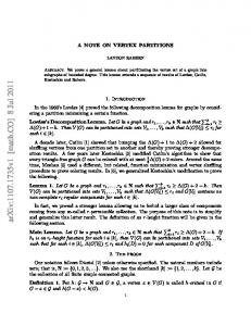
Figure 6: Lit morphing example.
5.2.4 Vertex State Programs Vertex state programs belong to a second program target supported by NV_vertex_program. Rather than being initiated implicitly when a vertex is provoked, vertex state programs are explicitly executed. Unlike a provoked vertex program, no vertex is forwarded to primitive assembly. Instead a vertex state program provides a way to update program parameter registers.
To improve ease of use, NV_vertex_program can track matrix state into 4 contiguous designated program constants. For example, the inverse transpose of the modelview matrix can be tracked into program parameters 4 through 7 with the command:
6 EXAMPLES 6.1 Lit Morphing Example This example shows how to implement a simple morph between a cube and sphere with one directional light as shown in Figure 6. Each vertex contains the following data. Cube position and normal are sent in attributes 0,1 and sphere position and normal are sent in attributes 2,3. The blend factor is sent in attribute 15 and is only sent once per object. The blend is done in object space and the lighting in eye space. The cube and sphere consist of about 2500 vertices each.
glTrackMatrixNV(GL_VERTEX_PROGRAM_NV, 4, GL_MODELVIEW, GL_INVERSE_TRANSPOSE_NV);
Given a matrix tracked this way, eye-space normals for lighting can be computed as follows: DP3 R0.x, c[4], v[NRML] ; DP3 R0.y, c[5], v[NRML] ; DP3 R0.z, c[6], v[NRML] ;
Additionally, the composite of the modelview and projection matrices is often used to transform positions directly from objectspace to clip-space. Consider:
The 21-instruction program below implements this example. The inverse transpose modelview matrix is tracked in program parameters 12-14, the composite matrix is in 4-7, the normalized light direction vector is in 20, the normalized half-angle vector is in 22, the specular power is in 21, and 21 also contains the ambient, diffuse, and specular color weighting.
glTrackMatriNV(GL_VERTEX_PROGRAM_NV, 0, GL_MODELVIEW_PROJECTION_NV, GL_IDENTITY_NV);
This permits vertex positions to be transformed directly to clip space as follows:
# blend normal and position MOV R3, v[3] ; MOV R5, v[2] ; ADD R8, v[1], -R3 ; ADD R6, v[0], -R5 ; MAD R8, v[15].x, R8, R3 ; MAD R6, v[15].x, R6, R5 ; # transform normal to eye space DP3 R9.x, R8, c[12] ; DP3 R9.y, R8, c[13] ; DP3 R9.z, R8, c[14] ; # transform position and output DP4 o[HPOS].x, R6, c[4] ; DP4 o[HPOS].y, R6, c[5] ; DP4 o[HPOS].z, R6, c[6] ; DP4 o[HPOS].w, R6, c[7] ; # normalize normal DP3 R9.w, R9, R9 ; RSQ R9.w, R9.w ; MUL R9, R9.w, R9 ; # apply lighting and output color DP3 R0.x, R9, c[20] ; DP3 R0.y, R9, c[22] ; MOV R0.zw, c[21] ; LIT R1, R0 ; DP3 o[COL0], c[21], R1 ;
DP4 o[HPOS].x, c[0], v[OPOS]; DP4 o[HPOS].y, c[1], v[OPOS]; DP4 o[HPOS].z, c[2], v[OPOS]; DP4 o[HPOS].w, c[3], v[OPOS];
OpenGL implementations internally maintain these composed and inverted matrices, so tracking these matrices into program constants is straightforward and obviates the application from manipulating and loading matrices. Our experience is that OpenGL developers appreciate the convenience of the matrix tracking facility. Matrix tracking contributes to ease of use because developers can rely on OpenGL’s existing conventions for establishing 3D views and hierarchical modeling. Moreover, NV_vertex_program specifies additional tracking matrices that serve no other purpose but matrix tracking. Vertex program may manipulate and track these matrices for their own purposes. For example, these additional matrices may provide a set of bone transforms. These extra matrices provide forward focus by encouraging applications to manage their own 4x4 transforms.
Our GeForce3 GPU running at 200MHz is able to process these vertices at a rate of about 8 million/sec. This includes view frustum clip check, perspective divide and viewport/depthrange
155
transform. Assuming the vertex attributes are sent as floats, a bandwidth of about 400 MB/sec is required into the chip.
6.2 Anisotropic Lighting Example This example shows how vertex programs can be used to implement an unconventional per-vertex lighting model. Heidrich and Seidel [12] describe a lighting model for anisotropic surfaces that is significantly different than the standard OpenGL lighting model. Their anisotropic model computes the intensity on an anisotropic surface for a single light source as
Kd 1 − ( L • T ) 2 + I = Ka + Sself Ks 1 − (L • T) 2 1 − (V • T) 2 − (L • T)( V • T) shine where
(
Sself
=
1,
L• N ≥ 0
0,
L•N 0) ? sqrt(1-(L dot T)^2) : 0 SGE R3.z, R3.w, c[24].y ; MUL R4.x, R3.z, R3.y ; # V dot T DP3 R5.x, R0, R2 ; # sqrt(1-(V dot T)^2) MAD R5.y, R5.x, R5.x, -c[24].w ; RSQ R5.z, -R5.y ; MUL R5.y, -R5.y, R5.z ; # (L dot T) * (V dot T) MUL R5.w, R3.x, R5.x ; MAD R4.y, R3.y, R5.y, R5.w ; # shininess = c[24].x MOV R4.w, c[24].x ; LIT R6, R4 ; # color = Kd * diffuse + specular + Ka MAD R7, R6.y, c[40], R6.z ; ADD o[COL0], R7, c[41] ;
The 27-instruction vertex program below constructs the tangentspace basis at each vertex of a tessellated patch and then
156
constructs a 3x3 transform from tangent space to cube map space for use as the texel matrix. The program also computes the view vector in cube map space. The 3x3 matrix and vector are combined into a 4x3 matrix that is output as texture coordinates for use by the properly configured texturing engine. The program also passes through the (s, t) texture coordinates to address the normal map texture. The program assumes that the modelview-projection composite matrix is tracked in program parameters 0-3; the 3x3 transform from object space to cube map space is loaded in program parameters 20-22; the 4x3 transform from negated object space to cube map space is loaded in program parameters 40-42; the gradients in terms of the patch's u and v parameters are evaluated into vertex attributes 1 and 2; and a 2D texture coordinate is evaluated into first texture coordinate set 0. DP4 o[HPOS].x, c[0], v[OPOS]; DP4 o[HPOS].y, c[1], v[OPOS]; DP4 o[HPOS].z, c[2], v[OPOS]; DP4 o[HPOS].w, c[3], v[OPOS]; # Normalize tangent: R0 = normalize3(v[1]) DP3 R0.w, v[1], v[1] ; RSQ R0.w, R0.w ; MUL R0.xyz, v[1], -R0.w ; # Calc normal: R2 = cross(R0,v[2]) MUL R2, R0.zxyw, v[2].yzxw; MAD R2, R0.yzxw, v[2].zxyw, -R2; # Normalize normal: R2 = normalize(R2) DP3 R2.w, R2, R2 ; RSQ R2.w, R2.w ; MUL R2.xyz, R2, R2.w ; # Calc binormal: R1 = cross(R0,R2) MUL R1, R0.zxyw, R2.yzxw ; MAD R1, R0.yzxw, R2.zxyw, -R1; # Concatenate the 3x3 tangent space basis with the # 3x3 transform from object space to cube map space # to texture coordinates (s1,t1,r1;s2,t2,r2;s3;t3;r3). DP3 o[TEX1].x, c[20], R0 ; DP3 o[TEX1].y, c[20], R1 ; DP3 o[TEX1].z, c[20], R2 ; DP3 o[TEX2].x, c[21], R0 ; DP3 o[TEX2].y, c[21], R1 ; DP3 o[TEX2].z, c[21], R2 ; DP3 o[TEX3].x, c[22], R0 ; DP3 o[TEX3].y, c[22], R1 ; DP3 o[TEX3].z, c[22], R2 ; # Convert object-space position into cube map-space view # vector and put into (q1,q2,q3) DP4 o[TEX1].w, v[OPOS], c[40] ; DP4 o[TEX2].w, v[OPOS], c[41] ; DP4 o[TEX3].w, v[OPOS], c[42] ; # Output normal map texture coordinate to TEX0 MOV o[TEX0], v[TEX0] ;
Figure 8: Bump environment mapping. fragment processing. We also expect to see the development of shading languages that automatically exploit GPU programmability [22].
8
9
REFERENCES
[1]
Advanced Micro Devices. 3DNow Technology Manual. www.amd.com/K6/k6docs/pdf/21928.pdf Kurt Akeley. RealityEngine Graphics. In James T. Kajiya, editor, SIGGRAPH 93 Conference Proceedings, Annual Conference Series, pages 109–116. ACM SIGGRAPH, Addison Wesley, August 1993. Kurt Akeley and Tom Jermoluk. High Performance Polygon Rendering. In John Dill, editor, Computer Graphics (SIGGRAPH 88 Conference Proceedings), volume 22, pages 239-246. Addison Wesley, August 1988. Brian Apgar, Bret Bersack, and Abraham Mammen. A Display System for the Stellar Graphics Supercomputer Model GS1000. In John Dill, editor, Computer Graphics (SIGGRAPH 88 Conference Proceedings), volume 22, pages 255-262. Addison Wesley, August 1988. James H. Clark. The Geometry Engine: A VLSI Geometry System for Graphics. In R. Daniel Bergeron, editor, Computer Graphics (SIGGRAPH 82 Conference Proceedings), volume 16, pages 127 133. Addison Wesley, July 1982. DirectX Home. http://www.microsoft.com/directx Nick England. A Graphics System Architecture for Interactive Application-Specific Display Functions. IEEE Computer Graphics and Applications, 6(1): 60-70, January 1986. I. Ernst, D. Jackèl, H. Rüsseler, O. Wittig, Hardware Supported Bump Mapping: A Step towards Higher Quality Real-Time Rendering, 10th Eurographics Workshop on Graphics Hardware, August 28-29, 1995, pp. 63-70. Sam Fuller. Motorola’s AltiVec Technology. Motorola Inc.
[2]
[3]
Examining the above program, observe how support for programmable geometry serves as the computational bridge between the outputs of the surface engine and the fragment-level data requirements for bump environment mapping. Programmability allows many variants of the basic technique described above including interactive control of the bump scale, convincing refraction effects, and diffuse lighting contributions.
7
ACKNOWLEDGEMENTS
We are grateful to the following individuals for their contributions to the design and implementation of the GeForce3’s vertex engine: Simon Moy, David Kirk, John Montrym, Steve Glanville, and Chas Boyd. Thanks to Andrew Webster and Cass Everitt for the examples in Sections 6.2 and 6.3. We thank Bill Mark, Doug Voorhies, and our anonymous reviewers for their help improving this paper.
[4]
CONCLUSIONS
[5]
We have presented the design and implementation of the GeForce3’s user-programmable vertex engine. While the design evolved from a modally controlled architecture, it supports a simple yet powerful programming model and preserves the original design’s efficiency and high performance. Our design shows that efficiency, performance, and ease of programming need not be mutually exclusive. In particular, all instructions have single cycle repeat rate with no penalty for either input swizzling and sign control or masking of the output. By integrating data formatting, floating point unit utilization and overall performance is maximized in a single-issue implementation.
[6] [7]
[8]
[9]
We view vertex processing as an evolutionary step toward greater GPU programmability. Our future work will focus on increased programmability of geometry processing, and programmable
157
[10] Henry Fuchs, John Poulton, John Eyles, Trey Greer, Jack Goldfeather, David Ellsworth, Steve Molnar, Greg Turk, Brice Tebbs, and Laura Israel. Pixel-Planes 5: A Heterogeneous Multiprocessor Graphics System Using Processor-Enhanced Memories. In Jeffrey Lane, editor, Computer Graphics (SIGGRAPH 89 Conference Proceedings), volume 23, pages 79-88. Addison Wesley, July 1989. [11] Chandlee Harrell and Farhad Fouladi. Graphics Rendering Architecture for a High Performance Desktop Workstation. In James T. Kajiya, editor, SIGGRAPH 93 Conference Proceedings, Annual Conference Series, pages 93–100. ACM SIGGRAPH, Addison Wesley, August 1993 [12] Wolfgang Heidrich and Hans-Peter Seidel, Efficient Rendering of Anisotropic Surfaces Using Computer Graphics Hardware, Image and Multi-dimensional Digital Signal Processing Workshop, 1998 [13] Intel. I860 Microprocessor Family. Programmer’s Reference Manual. 1992. ISBN 1-55512-165-9. [14] IA-32 Intel Architecture Software Developer’s Manual Volume2: Instruction Set Reference. Copyright 1997-2000 Intel Corporation. [15] David Kirk and Douglas Voorhies. The Rendering Architecture of the DN10000VS. In Forest Baskett, editor, Computer Graphics (SIGGRAPH 90 Conference Proceedings), volume 24, pages 299– 307. Addison Wesley, August 1990. [16] A. Kunimatsu, N. Ide, T. Sato, Y. Endo, H. Murakami, T. Kamei, M. Hirano, M. Oka, A. Ohba, T. Yutaka, T. Okada, and M. Suzuoki. 5.5 GFLOPS Vector Units for Emotion Synthesis. Conference Record, Hot Chips 11, August 15-17, 1999, Stanford University, Palo Alto, California. [17] Adam Levinthal and Thomas Porter. Chap – A SIMD Graphics Processor. In Hank Christiansen editor, Computer Graphics (SIGGRAPH 84 Conference Proceedings), volume 18, pages 77–82. Addison Wesley, July 1984. [18] MIPS Technologies Inc. MIPS-3D ASE: 3D Graphics Application Specific Extension. www.mips.com/products/3d.pdf [19] Steven Molnar, John Eyles and John Poulton. PixelFlow: HighSpeed Rendering Using Image Composition. In Edwin E. Catmull, editor, Computer Graphics (SIGGRAPH 92 Conference Proceedings), volume 26, pages 231–240. Addison Wesley, July 1992. [20] NVIDIA Corporation, NVIDIA OpenGL Extension Specifications, Mark Kilgard, editor, May 2001. http://www.nvidia.com/developer [21] Mark Peercy, John Airey, Brian Cabral, Efficient Bump Mapping Hardware, Computer Graphics (SIGGRAPH 97 Conference Proceedings), pages 303-306. Addison Wesley, August 1997. [22] Kekoa Proudfoot, William Mark, Svetoslav Tzvetkov, and Pat Hanrahan. A Real-Time Procedural Shading System for Programmable Graphics Hardware, Computer Graphics (SIGGRAPH 2001 Conference Proceedings), Addison Wesley, August 2001. [23] John Montrym, Daniel Baum, David Dignam and Chris Migdal. InfiniteReality: A Real-Time Graphics System. In Turner Whitted, editor, SIGGRAPH 97 Conference Proceedings, Annual Conference Series, pages 293–302. ACM SIGGRAPH, Addison Wesley, August 1997. [24] Michael Potmesil and Eric Hoffert. The Pixel Machine: A Parallel Image Computer. In Jeffrey Lane, editor, Computer Graphics (SIGGRAPH 89 Conference Proceedings), volume 23, pages 69–78. Addison Wesley, July 1989. [25] Mark Segal and Kurt Akeley. The OpenGL Graphics System: A Specification (Version 1.2.1). www.opengl.org [26] John Torborg. A parallel processor architecture for graphics arithmetic operations. In Maureen C. Stone, editor, Computer Graphics (SIGGRAPH 87 Conference Proceedings), volume 21, pages 197–204. Addison Wesley, July 1987. [27] Channing Verbeck. Personal communication. December 2000. [28] Douglas Voorhies, Jim Foran, Reflection Vector Shading Hardware, Computer Graphics (SIGGRAPH 94 Conference Proceedings), pages 163-166. Addison Wesley, July 1994.
Chromatic aberration through a bunny in the Uffizi Gallery, Florence. A vertex program computes three pseudo-refraction vectors for red, green, and blue, each with a different index of refraction. Each refraction vector samples a single RGB environment cube map. The red, green, and blue contributions from each environment map access are combined. A fourth cube map texture access contributes conventional RGB environment mapping using a reflection vector also computed by the vertex program. Credit: Simon Green.
Indexed matrix skinning of a running jester. Executing a single static display list renders each jester instance. Each vertex contains a position, a normal, 2D texture coordinate, and 4 matrix index/weight pairs. The vertex program uses relative addressing to transform and weight each vertex position and normal by its appropriate matrix set. The animation is accomplished by varying matrices stored as program constants. Credit: Sebastien Domine.
Dynamic cloth simulation with mesh deformation, bump mapping, and simple ray tracing. The vertex program displaces the flag’s mesh away from the ball when contact would otherwise occur. The same program does bump mapping setup for the flag’s surface. The program also computes a local reflection (circled in the image) of the green ball via ray casting. Written in DirectX 8. Credit: Doug Rogers.
158