A Vector-Based Gyro-Free Inertial Navigation System by Integrating Existing Accelerometer Network in a. Passenger Vehicle. Ying Kun Peng, and M.F. ...
A Vector-Based Gyro-Free Inertial Navigation System by Integrating Existing Accelerometer Network in a Passenger Vehicle Ying Kun Peng, and M.F. Golnaraghi Department of Mechanical Engineering, University of Waterloo Waterloo, ON N2L 3G1 Canada Abstrncl -Modern automotive electronic control and safety systems, including air-bags, anti-lock brakes, anti-skid systems, adaptive suspension, and yaw control, rely extensively on inertial sensors. Currently, each of these sub-systems uses its own set of sensors, the majority of which are low-cost accelerometers. Recent developments in MEMS accelerometers have increased the performance limits of mass-produced accelerometers far beyond traditional automotive requirements; this growth trend in performance will soon allow the implementation of a gyro-free inertial navigation system (GF-INS) in an automobile, utilizing its existing accelerometer network. We propose, in addition to short-term aid to GPS navigation, a GF-INS can also serve in lieu of more expensive and less reliable angular rate gyros in vehicle moment controls and inclinometers in anti-theft systems. This work presents a modified generalized GF-INS algorithm based on four or more vector (triaxial) accelerometers. Historically, GF-INS techniques require strategically-placed accelerometers for a stable solution, hence inhibiting practical implementations; the vector-based GF-INS allows much more flexible system configurations and is more computationally efficient. An advanced attitude estimation technique is presented, utilizing coupled angular velocity terms that emerged as a result of the intrinsic misalignment of real vector accelerometers; this technique is void of singularity problems encountered by many prior researchers and is particularly useful when error due to the integration of angular accelerations is prominent, such as in low-speed systems or long-duration navigations. Furthermore, an initial calibration method for the vector-based GF-INS is In the experimental setup, four vector presented. accelerometers, based on Analog Devices accelerometers, are assembled into a portable, one cubic-foot, rigid structure, and the data is compared with that of a precision optical position tracking system. Finally, the feasibility of a GF-INS implementation in an automobile is assessed based on experimental results.
I. INTRODUCTION Modern automobiles employ a multitude of inertial sensors for their onboard control and safety systems. These include, but. are not . . limited . to, the following subsystems [51,[111,[121: 1, Adaptive suspension 2. Anti-lock brake system (ABS) 3. Anti-theft system 4. Adaptive power steering 5. Crash sensing for airbag control 6. Electronic parking brake system (EPB) I . Rollover control 0-7803-8416-4/04/$20.00 02004 IEEE.
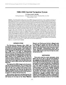
8. Vehicle dynamic control (VDC) 9. Yaw control Beyond traditional passive mechanisms, modern active versions of these subsystems all rely on the same types of MEMS (micro electro-mechanical systems) inertial sensors, namely linear accelerometers, angular rate gyros, and inclinometers. While most new passenger vehicles include at least a few of these subsystems, many of the subsytems still operate independently, and a full integration of these is the logical and inevitable next step to reduce cost [5],[121. In fact, today’s high-end passenger vehicles can incorporate more than 15 axes of inertial sensors [12], and significant redundancy can be seen in Fig. 1. However, full integration is often inhibited by increased number of system parameters and therefore a more complex central computer. In this work we propose an integrated, accelerometer-only system which introduces significant cost savings in hardware and a generalized design that can be easily ported among different vehicles. We summarize the main concepts behind the motivation: i. Accelerometers are reliable and inexpensive. Recent design and fabrication advancements in MEMS accelerometers are fast exceeding those of gyros and inclinometers, and more accelerometers are already being used in vehicles than the other two sensors. A s a result, in automotive-grade sensors, accelerometers can be considerably cheaper than gyros and inclinometers. Furthermore, inherent design challenges of MEMS gyros and inclinometers make them physically less reliable than accelerometers [13]. ii. Accelerometers can replace inclinometers. The latter are either expensive fluid-filled devices or they use fragile micro-machined pendulums. Accelerometers can replace them by sensing the direction of gravity, although possibly with reduced accuracy. However, in anti-theft systems and EPBs, where inclinometers are used [ I l l , these systems do not necessarily require the precision; hence inexpensive accelerometers are an attractive alternative. iii. A network of accelerometers can replace gyros, based on the concept of a gyro-free inertial navigation system (GF-INS). An accelerometer network can be used to determine angular acceleration (instead of angular velocity output from gyros), the performance of which increases proportionally to the linear
234
Authorized licensed use limited to: National Taiwan Ocean University. Downloaded on April 14, 2009 at 08:43 from IEEE Xplore. Restrictions apply.
Fig. 1. Inertial sensors used in high-end vehicles loday [12].
displacement between the accelerometers. If the sensors are placed at opposite ends of a vehicle, the performance gain can meet or surpass that of gyros. iv. A vector-based GF-INS proposed in this paper is easy to configure; accelerometers can be placed almost anywhere in the vehicle as long as the displacement between each accelerometer is fixed and known. Furthermore, there is only one initial calibration model, also presented in this paper, because only one type of sensor is involved. The first concept also represents the historical motivation for a GF-INS as an alternative to traditional INS, which uses three gyros and three accelerometers (3G3A-INS). The second concept has been thoroughly discusscd in literatures and can be found in manufacturers’ application notes. The third and the fourth concepts are presented in this paper. An added benefit is that the conccpt of a GF-INS will also be capable as an aid to Global Positioning System (GPS) navigators in a vehicle. Integration of GPS and INS combines the complementary aspects of the high output rate of the INS with the long term stability of the GPS to improve navigation output; the fusion of GPS and GF-INS, in particular, is reviewed in Kim [4] and Park [7]. In this paper, a prototype GF-INS system is built; its data represent one of the very few experimental results on GF-INS. Finally, the fcasibility of such systems is discussed. 11.
strategic placement of accelerometers on the host vehicle, including early publications by Padgaonkar 161 and Schuler [ 9 ] , and the most recent attempt by Chen [ 2 ] and Park (71, whose methods allow angular and linear dynamics to be decoupled from the system equations using only six accelerometers; in fact, Mostov [SI had proposed a GF-INS for an automobile based on Chen. Aside from vehicular navigation, Ang [I] had compared a GF-INS with a 3G3A-INS, fitted onto a microsurgical probe, and demonstrated the advantages of a GF-INS in that specific case. These past techniques are, however, impractical for implementation in a non-specific system due to their stringent configuration constraints. For example, Chen’s 121 proposal requires six single-axial accelerometers to be placed diagonally at the center of each of the six faces of a rigid cube; while Park [7] showed a feedback algorithm that compensates for sensor misalignment in Chen’s system, the algorithm turned out to be unstable. On the other hand, a practical, low-cost system needs to be easy to configure, with more generalized equations, in order to reduce calibration efforts. The GF-INS technique we propose, based on Parsa 181, uses a network of four or more vector accelerometers (i.e. triaxial accelerometers) in a GF-INS. Such vector-based GF-INS allows individual triaxial assembly to be placed in flexible locations within a rigid body, with only two requirements: (1) one vector accelerometer must be located at the center of the vehicle (the origin); ( 2 ) the accelerometers cannot be all coplanar. The linear displacement between the sensors should also be maximized where possible in order to increase system resolution. The result is a flexible configuration suitable for a real system, with performance potential matching or surpassing that of gyros.
B. Configuration in an Automobile Fig. 2 shows an example of sensor locations on a vehicle. Accelerometers used in a vehicle are typically in the < 5g range, except for airbag crash sensors which use > 5Og sensors. For the purpose of dynamics control and INS, the low-g accelerometers may be more suitable for the integrated system as they will provide more resolution. Based on Fig. 2 , the four satellite sensors,may be replaced
GF-INS
A . Background Due tu inherent design difficulties in miniaturization, MEMS gyros are generally more inferior in terms of noise, accuracy, linearity, cost, and mechanical durability compared tu accelerometers. GF-INS emerged as a solution, among various proposals which all use a network of accelerometers to replace gyros in a 3G3A-INS. In theory, a GF-INS requires a minimum of six sensors, although it has been shown in various literatures that a minimum of nine accelerometers is needed for a stable system. Most previous efforts on GF-INS tend to emphasize on the
Crash Deteetlon System
t satellite smror
Vehicle Dynamic ConizolSyrtcm Navigation I Dnvcr Information System BodylChawr Control System
A Seatbelt Pretensioner
Avbag
Fig. 2. Inertial sensor clustm in a passenger vehicle 1121
235
Authorized licensed use limited to: National Taiwan Ocean University. Downloaded on April 14, 2009 at 08:43 from IEEE Xplore. Restrictions apply.
with vector accelerometers, and the center inertial measurement unit (IMU) cluster, which consists of three gyros, three accelerometers, and a dual-axis tilt sensor, may be replaced with a single vector accelerometer. In this scenario, we have increased the number of measurement axes by 3, but considering MEMS gyros are typically 2-3 times more expensive than MEMS accelerometers, the elimination of gyros has already justified the cost of adding accelerometers. The accelerometers should not be all coplanar; in this example configuration, at least one vector accelerometer should be vertically offset from the rest. If the satellite sensors can be doubled as airbag sensors, then additional cost savings can be achieved. This would be possible in the near future as higher-g accelerometers become capable of increased resolution.
known, although the equation is nonlinear in the states. If fc can be measured by placing a vector accelerometer at the origin, these states can then be subtracted from
We focus on short-term, local area navigation for our development of the GF-INS. For this we assume a flat, non-rotating earth where the accelerometer measurements are not affected by the rotation of the earth. Further, we assume constant gravity. In general, these miniscule differences in acceleration outputs are undetectable by automotive-grade sensors. The dynamic acceleration vector of an arbitrary point P on a rigid body is given by
(1)
where -6J;
- 0: w p , - l,ilz
1
6Jp"
+ dJy
6J,q
-rix
-6J:
- 0;
'
(3)
Hence, we get an equation linear in the rotational states of the body. However, as well as dynamic accelerations, an accelerometer also measures static acceleration (i.e. gravity). We write the accelerometer measurement at P and at Cas
ap = rp+ g , and a, = r;. + g .
(4)
Then, in terms of accelerometer measurements, (2) becomes (1)
ap-a, =Wrp/,. where ic =the linear acceleration at the origin of the body, C; kc
5 , and
can be rewritten in matrix form as
upJ, +Uz -w: -u: 6J,q -by #,WZ + ur
C. GF-INS Algorithrrz
r --r ~+wx(wxr,,,)+iUxr,,,,
It is apparent from (1) that both rotational and translational dynamics of a rigid body can be solved given acceleration measurements at some points and with the moment arm
= t h e displacement vector from C to P ;
w = angular velocity vector;
6 = angular acceleration vector. Fig. 3 illustrates the kinematics of a free-moving body, with xyz (body) coordinates, relative to a fixed XYZ (inerrid) coordinates. All vectors used in this paper are referenced to the body coordinates.
Consequently, whereas most other authors attempted to devise GF-INS designs based exclusively on satellite accelerometers, by placing a vector accelerometer at the origin, we have two major accomplishments: first, linear and rotational dynamics of the vehicle can be simply decoupled without the complicated configuration required by most GF-INS techniques; second, gravity is automatically and completely removed in (5). Equation ( 5 ) can be written in terms of the accelerometer network in the system. Let a, be the n-th satellite vector accelerometer, and define A=[a,-a,
... a,-a,],and
a,-a,
R=[4c
4r
"'
rdc].
Equation (5) can then be expanded to A=WR.
A least squares solution to
dz
(5)
w =A
w
is
R (~R R ' ~ '
Fig. 3. Kinematics uf a rigid body.
236
Authorized licensed use limited to: National Taiwan Ocean University. Downloaded on April 14, 2009 at 08:43 from IEEE Xplore. Restrictions apply.
Equation (7) reveals that the optimal system configuration consists of 3 satellite accelerometers, where U becomes square and the solution to W involves one simple matrix inversion. Recall (3), angular acceleration can be extracted from W as
Integrating (8) with respect to time gives angular velocity; together with linear acceleration measurements aC, we have obtained all six measurements available to a 3G3A-INS. An additional step of integration is the primary disadvantage of a GF-INS, compared to a 3G3A-INS. Uncompensated DC bias and colored noise result in accumulated error in time. A proven technique to improve the performance of an INS is the implementation of Kalman Filters (KF). A KF provides stochastically optimal estimates of system states based on noisy measurements. KF algorithms for INS are thoroughly discussed in literatures and will not be discussed here. An implementation of KF for GF-INS is presented in detail by Kim [4]. The GF-INS concept could be applied to other purposes than vehicular navigation. In VDC systems, controllers may be redesigned to work with angular accelerations. In these applications, the effects of small uncompensated biases are generally insignificant, and a GF-INS-based controller can be as effective and stable as a gyro-based system. Angular Velocily Correction Algorithm Equation (3) shows that W contains quadratic angular velocity terms in addition to angular accelerations. If angular velocity can be efficiently solved, then a GF-INS can replace gyros synonymously by eliminating one integration step. We define quadratically-coupled angular velocity ( ) and
quadratically-coupled terms to solve for the magnitude of angular velocity components, such as
but the method is highly susceptible to singularity problems, in addition to the possibility of an imaginary solution. Since all real systems contain misalignment errors, neither (9) nor (IO) will remain zero during motion; all these information can then be used advantageously to devise a more robust method. If we let f i y be the calculated angular velocity (about y-axis) after integrating (S), and
4 be
the
corrected angular velocity, then the following equality should hold
+ d,fiy-( 4 cy.,)
=0 .
(12)
Equation (12) can be solved as a quadratic equation
The positive and the negative solutions of (13) are then compared with a, to determine the suitable answer. Since the denominator is a constant, the solution is free of singularity problems. Equation (13) is nonetheless still predisposed to imaginary solutions when noise is present. In this case, an ambiguous solution most often occurs when both 0, and 0: are close to zero. Stochastically, the chances of an imaginary solution can be reduced in half by using an additional equation analogous to (13), i.e. we replace 61, terms with 0, terms:
angular velocity square ( d )terms, which can be solved from
(7) as Compared to ( I l ) , indefinite solutions to (13) and (14) can be predicted, whereas no such mechanism is provided in ( 1 I). Equations (13) and (14) can be similarly applied for 4 and
4, respectively.
Angular velocity cannot be directly solved with (9) or (IO). Most prior GF-INS literatures assume well-aligned sensors, in which case some components of (9) or (10) are always zero during motion. Some authors have then suggested using
D. Parametric Calibration of a Real Vector Accelerometer Precise initial calibration of a real accelerometer is crucial to ensuring a robust system. A major advantage of an accelerometer-only system compared to a system with a variety of sensors is that only one calibration model is needed, hence only one type of calibration tests needs lo be done and one set of computer codes to b e written.
23i7
Authorized licensed use limited to: National Taiwan Ocean University. Downloaded on April 14, 2009 at 08:43 from IEEE Xplore. Restrictions apply.
The parametric model of a real vector accelerometer can be written as
i = G (r,. +ox (w xr,,?) + ixrOip+ g) + b + va,
(15)
where
6 = the voltage output of a vector accelerometer;
G = the scale factor matrix; = t h e gravity vector; b = the D C bias vector; v,, = the noise vector. The scale factor matrix accounts for both the scale conversions and misalignment of the sensors. For example, if the sensors are perfectly aligned to the body coordinates, then only the diagonal elements are nonzero. Gravity is set at 9.8065m/si for the purpose of our prototype system. The noise is assumed white and Gaussian. This assumption is generally valid for most current commercial accelerometers. In the end, we have 15 parameters to estimate for a single vector accelerometer assembly, including 9 scale factors, a 3-element displacement vector, and a 3-element bias vector. Given truth motion data, f ? , o , and d , optimization of
should be able to resolve angular accelerations above 0.139md/s2 or i.98°/s’ , for rotations about a single axis. Consider an average passenger sedan with a dimension of l.Bx4.8m;if accelerometers are placed along the sides of the vehicle, then the resolution can be reduced to 0.0232rad/s2 or 1.33p/s’; if accelerometers are located at the front and rear bumpers, then the resolution can be further reduced to 0.00871rad/s2 or 0.499°/s2. In comparison, low-cost gyros, such as ADI’s ADXR-series gyros, typically have a resolution no better than O . ~ Q /given ~ the same test conditions. The maximum resolution for rollover detection, however, will likely be poorer due to a much smaller vertical dimension of a typical vehicle. B. Experiment Setup Two sets of experiments were conducted. The first was to calibrate accelerometer parameters and the second set for GF-INS experimentations. Precision truth data is obtained from OPTOTRAKB, an optical position tracker from Northern Digital Inc. (NDI, Waterloo, ON, Canada). The OPTOTRAK traces three-
parameters can be done with a nonlincar least squares method. A s most triaxial accelerometers are assembled from three single-axial accelerometers, an important assumption of (15) is that all three single-axial accelerometers coincide at the same origin. This assumption is valid if the displacement of each accelerometer from the true origin is very small. Moreover, (15) does not account for sensor nonlinearities, such as bias drift and temperature sensitivity. In reality, the automotive-grade sensors of interest are typically noisy enough that the above assumptions and calibration errors in the order of a few centimeters or a few degrees make little differences (see Section 111-D). As a result, the model discussed here is adequate for automotive-grade sensors.
Fig. 4. Vector accelerometer assembly and it? analog circuits
111. EXPERIMENTS A. Protoype System The prototype system is based on a one-foot cubic cage and four vector accelerometers bolted at four corners of the enclosure. The cage is fabricated from rigid and light-weight aluminum bars with all joints permanently welded to ensure rigidity and minimize secondary vibrations of the structure. Each vector accelerometer consists of two orthogonallymounted, dual-axis ADXL311 accelerometers from Analog Devices (ADI, Norwood, MA). The full circuit, shown in Fig. 4, consists of anti-aliasing low-pass filters at 50Hz. Filtered analog output signals are digitized at IOOOHz and processed with MATLAB R I 3 on a PC. The assembled prototype system is shown in Fig. 5. The average RMS noise of the accelerometer output was approximately 41.8msI/s2 . Given a one-foot (approximately 300mn1) moment arm between the accelerometers, the system
Fig. 5. Prutotypc GF-INS system with vector accelerometers encircled.
238
Authorized licensed use limited to: National Taiwan Ocean University. Downloaded on April 14, 2009 at 08:43 from IEEE Xplore. Restrictions apply.
dimensional position of its designated markers, which are attached to the moving body of interest, relative to a groundfixed camera station, with a claimed accuracy of 0.05mm. Through a series of kinematical calculations, the translational and rotational dynamics of the body (i.e. w , iu, and ic) are derived from these position data. The accelerometers are labeled from 1 to 4, where accelerometer 1 is assigned as the origin. The experiment setup is shown in Fig. 6.
C. Calibration Results The ideal calibration experiments should separate rotational and linear-translation tests; however, these tests are time-consuming and require expensive robots capable of generating complex, high-speed motions. With a system as large as an automobile, such tests are unreasonable. In reality, the calibration experiments need not be systematic. Given sufficient data points and a reasonable initial guess, the nonlinear least squares method should he able to identify the parameters correctly. TCIdo so we performed an experiment where the system is randomly moved and rotated at different speeds in %' space; the calibration results for accelerometer 1 using these data is shown in Table I . The results of Table 1 demonstrate that our hand-mounted sensors are within only a few degrees of misalignment. This is important because in automotive applications, sensors are usually calibrated offline prior to installation. As sensors are mounted onto a vehicle, we can expect small misalignment with respect to the body axes; this misalignment will likely he smaller than that found in our prototype system since the assembly process can he guided by robots. As will be shown in Section D, small misalignments amount to insignificant errors with automotive-grade sensors. Once again, small, uncompensated errors are only noteworthy for vehicular navigation purposes. Conversely, the system can be calibrated after installation at a much higher cost, hut with the benefit of an improved navigation system. In consequence, an automaker needs to find a balance between costly calibration efforts and system functionality requirements.
Fig. 6. Experiment setup. Encircled numbers: location of OPTOTRAK markers; An ("=I ...4): accelerometers; small arrows: locations and direction of accelerometer measurements: large arrows:origin (C) and its cwrdinates.
compared to actual angular acceleration and are most significant during high-jerk (derivative of acceleration) maneuvers. This is an expected result because of phase lag between the accelerometers and the optical truth data.. The implementation of a KF shows significant performance gain in Fig. 9. In fact, the x- and y-error covariances are reduced by more than 50%. It is common to find in literatures much higher attenuation if the stochastic characteristics of the system can be better understood. In Section C we mentioned the difficulty involved in calibrating an integrated sensor system on an automobile; we investigate next the effects of calibration errors. Fig. I O shows the angular acceleration differences when a IO-degree misalignment calibration error is introduced along the x-axis of accelerometer 2. Fig. 11 shows the differences when A n g u t Ac~eleratiOnIra& 50
D. GF-INS Results Fig. 7 shows the angular acceleration results for an experiment with relatively large rotational motions; the errors are shown in Fig. 8. The estimated angular acceleration appears closely matching the truth data. Errors are small
50 0
-
5
10
15
20
25
30
35
40
5
IO
15
20
25
30
31
40
TABLE I.CALIBRATION RESULTS FOR ACCELEROMETER 1
I
I
PARAMETER
VALUE
NOMINAL 5226
0
G
I
UNITS
CALIBRATBD
-1001
0
50
4347.4 89.812
13.316 4504.9
940.30 327.561
-232.98
-37.123
4769.7
J
I k c
(O.O,Ojr
(O,O.O)T
b
(0.0. O y
(4.1379.4.0353.0.2066)7
1
I
0
5
10
15
20
25
30
35
40
nms IS)
mm
Fig. 7. Angular acceleration results for an experiment with significant rotational dynamics.
V
239
Authorized licensed use limited to: National Taiwan Ocean University. Downloaded on April 14, 2009 at 08:43 from IEEE Xplore. Restrictions apply.
..
yI
2
5
I 5
'0
10
15
20
25
30
35
'0
40
I 5
10
15
20
25
30
35
40
... .~...
I
35
40
002,
-0.021 0
I
1
5
10
15
20
25
30
5
'0
5
10
15
20 Time (3)
25
30
35
40
Fig. IO. Angular acceleration e r o r due to il IO-degree misalignment calibration m o r along thsr-axis of accrleromrter 2.
Fig. 8. Angular acceleratiun eror for Fig. 7 Anqular Acceleralim Eimr iradis21
10
Calibation~hducdError (radlsz) 1
;
5
,."
I
2
IQ 0
0
5
10
15
20
25
30
35
40
~2
0
4
5
10
15
20
25
30
5
10
15
20
25
30
,
;.!,);..;:/.ij/;i."
35
40
I 10 -. 0
0
5
10
15
20
25
30
35
40
. 0~ ..................
z '0
5
10
15
20 Tlme
25
30
35
40
4
(I)
I
-2
5
10
, ,.k-.,/'";
,/ t,; .,,. ;, %1/! .'dI !1*,.A,,.*:'
i, 35
.,..,....
I 40
.
i IS
20
25
30
35
40
Tlme (5)
Fig. 9. Angular acceleration enor fur Fig. 7 after W.
Fig. I I . Angular acceleration error due to a 50displacement calibration e r o r of accelerometer 2.
accelerometer 2 is offset from its true coordinates by 50mm. In both scenarios, the differences were very small compared to the actual angular acceleration of the vehicle. This result reinforces our argument in Section C . The intentional errors introduced in Fig. 10 and Fig. 11 illustrate exaggerated scenarios. With robot-assisted assembly of a vehicle. sensor installation error will likely be insignificant to VDC applications.
Angular VdocfryCorrecrion Angular velocity solutions by direct integration of angular acceleration and by using (13) and (14) are compared in Fig. 12; the errors are shown in Fig. 13. The corrected angular velocity appears much noisier than the results of direct integration; the solution is inconsistent when angular velocity is close to zero, which is expected. However, it is evident, particularly near the end of the experimental data, that the method can effectively eliminate integration error.
As we focus on short-term navigation and vehicle dynamic control applications, the results of Fig. 12 and Fig. 13 are less important. However, although the technique appears to be insufficient to completely replace the function of a gyro, (13) and (14) provide a useful internal correction mechanism for a GF-INS during prolonged navigation.
Graviplnduced Error Angular acceleration error can he much larger than those shown in Fig. 9 in some cases. In our experiments, and in most automotive scenarios, dynamic acceleration seldom exceeds 1-26, except during impact, on severely rough roads, or when the vehicle is out of control. Thus, the major component in the accelerometer output will be gravity. In fact, since uncompensated gravity can lead to major errors in the cstimation of dynamic translational motion, traditional INS research devotes significant efforts in gravity estimation.
240
Authorized licensed use limited to: National Taiwan Ocean University. Downloaded on April 14, 2009 at 08:43 from IEEE Xplore. Restrictions apply.
Angular Acceleration (rBd1s2) 5
. o
P -51 0
5
10
15
20
25
30
35
5,
-5 I
0
5
10
15
20
25
30
35
i40
-5 -10
a
1
Mi
40
-20I 0
5
10
15
25
20
30
35
40
I
I 5
10
15
25
20
30
35
40
'1
-5 1 0
,
d 5
10
15
M
25
30
35
0
40
5
10
15
I
,
\
I
, 25
20
30
35
40
m e (31
I m e ($1
Fig. 12. Angular velocity results.
Rg. 14. Angular acceleration results for an erpeCment with significant gravity components. Angular AcCsleration Enor iradi.') 10
1.5
,r
I
I
1
0.5
0'
5
10
15
20
25
XI
35
40
3
I
2
I
15,
6
I '
I
"34
'8
II
e 1
- 2
0 0'
5
10
15
XI
25
30
35
0
40
mme (I)
10
15
20 mme (*I
25
30
35
40
Fig. 15. Angular acceleration enor for Fig, 14
Fig. 13. Angular velocity error for Fig. 12
In the case of GF-INS, uncompensated gravity can also affect attitude estimation. In general, if the motion is planar, gravity can be treated as a constant DC bias which can be accurately estimated when the vehicle is at rest initially and subtracted. This is not true, however, when the motion is three-dimensional. The experiment for Fig. 7 consists of angular motions prominently about x- and y-axes, i.e. the motion is near planar. Fig. 14 shows the worst case of all our experiments, where angular components of the dynamic acceleration is small compared to gravity and the motions are non-planar, and Fig. 15 shows the errors for Fig. 14. The first 20 seconds of experiment is still near planar, and the errors are still relatively small; as the system rotated far off the plane, gravity-induced errors become apparent.
5
Iv. FEASIBILITY AND CONCLUSION In discussion of the feasibility of a GF-INS-based, integrated inertial system for a passenger automobile, we begin by summarizing key results and analyses: I. Automotive-grade sensors are noisy. As a result. small calibration error is insufficient to degrade system performance by much. Costly calibration after installation may be avoided if the assembly process of the car can be carefully designed to limit misalignment within a "small" range. 2. In navigation, a GF-INS can be used as a high-output aid lo GPS. Although integration error can increase as calibration effort is saved. The use of angular velocity correction method (13) and integration with other onboard sensors such as wheel-speed sensors can also be beneficial.
24 1
Authorized licensed use limited to: National Taiwan Ocean University. Downloaded on April 14, 2009 at 08:43 from IEEE Xplore. Restrictions apply.
In vehicle dynamic control applications, a GF-INS can satisfactorily replace gyros. Calibration errors are not very important in these areas as controllers can easily be redesigned. A GF-INS can be very vulnerable to uncompensated gravity. Fortunately, this is generally more tolerable in nearly-planar motions such as those experienced by daily driving. An integrated system requires the cooperation among developers of subsystems. This can be a costly path but the long term benefit is imminent. In particular, the cost savings from the use of an accelerometer-only system, eliminating gyros and inclinometers, can be significant. vector-based GF-INS allows flexible configuration options that early GF-INS proposals fail to provide. This makes GF-INS a suitable integration mechanism for the existing accelerometer infrastructure in modern passenger vehicles. The performance of such a system can potentially match or exceed existing gyros and therefore eliminate these more expensive sensors. The result is minimal added hardware - perhaps a few more accelerometers, and large cost savings in terms of hardware. Aside from vehicular applications, GF-INS is also being explored in other applications beyond direct replacement for 3G3A-INS. For example, Ang [ 11 have proposed a GF-INS based system for a hand-held surgical probe; Kim [4] proposed a hybridized system using GF-INS and GPS to significantly enhance the performance of a 3G3A-INS. The flexible vector-based GF-INS presented in this work will surely find increased areas of application that previous GF-INS cannot offer.
for Implementation Using Low Cost Senson," IEEE P U N S , pp. 185-192,
ZWO. [4] Kim. A.. Peng. Y.K.. and Golnaraghi. M.F., "A Sensor Fusion Algorithm for GPS, Strapdown and Gyro-Free Inertial Navigation Systems," Proceedings ofthe CSME Forum 2004.June 1-4.2004 (in press). [51 Mostov. K.S.. Soloviev. A.A., and Koo. T,.K.I., "Accelerometer Based Gyro-Free Multi-Sensor Generic Inertial Device for Automotive Applications." Proceedings of the IEEE Conference on Intelligent Transportation System, pp. 1047-1052. Nav 1997. [6] Padgaonkar, A.J.. Krieger, K.W.. and King, AS., "Measurement of Angular Acceleration of a Rigid Body Using Linear Accelerometen." Journnl ofApplirdMechunics. vol. 42, no. 3, pp. 552-556. Sep 1975. [7] Park, S.. and Tan. C.-W., "GPS-Aided Gyroscope-Free Inertial Navigation Systems," Colij%omio Partners fir Advanced Transit and Highways (PATH). Task Order 4224. Report UCB-ITS-PRR-2032-22, 2002. [SI Parsa. K.. Angeles. I., and Misra, A.K.. "Attitude Calibration of an Accelerometer Array," Proceedings of the 2002 IEEE lnternntional Conference on Robotics & Automnrion, pp. 129-134, May 2032. [91 Schuler, A.R., "Measuring Rotational Motion with Linear Accelerometers." IEEE Transaction on Aerospace and Electronic System, vol. AES-3, no. 3. pp. 465-471. 1967. IIOlTitlerton, D.H.. and Westun, J.L., Stropdown Inenid Navigotion Technology, United Kingdom: Peter Peregrinus Ltd.. 1997. [ I 11 VTI. "Automotive Applications." VTI Technologies website, Finland. (http://www.vti.fi/applicarions/automotive.html) [12]Weinberg, H.. "MEMS Sensurs are Driving the Automotive Industry", Sensors, vol. 19. no.2, pp. 36-41. Feb 2002. 1131Yazdi, N., Ayari, F., and Najafi, K., "Micromachined Inertial Sensors." Proc. IEEE, vol. 86, no. 8. pp. 1640-59,Aug 1998.
V.FUTURE W O R K The body of a moving automobile is constantly subject to vibrations and small mechanical deformations, which are less ideal than the prototype system presented in this paper. In theory, these non-ideal factors should appear as zero-mean noises in accelerometer signals - e.g. the body will always vibrate about its natural equilibrium - thus should not impose significant errors in the system output. A prototype system built on an automobile is required to completely assess the feasibility of the proposed GF-INS system. We would also like to extend this work beyond passenger vehicles to include large commercial and military land vehicles in the future.
REFERENCES W.T.. Khosla. P.K.. and Riviere, C.N., "Design of All-Accrlerometcr Inertial Measurement Unit for Tremor Sensing in Hand-held Microsurgical Instrument." Pruc. of the 2003 IEEE Intl. Conference on Robotics ondAutornntion, pp. 1781-1786, Sept 1994 [2] Chsn, 1.-H.. Lee. S.-C., and DeBra, D.B., '%yoscope Free Strapdown Inertial Measurement Unit by Six Linea! Accelerometers," Journal of Guidance. Conrrol. rmdDynnmics. vol. 17, no. 2, pp. 286-290. 1994. [3] Gebre-Egziabher. D.. Elkaim, GH.. Powell, J.D., and Parkinson, B.W., "A Gyro-Free Quaternion-Based Attitude Determination System Suitable
[ l ] Ang.
242
Authorized licensed use limited to: National Taiwan Ocean University. Downloaded on April 14, 2009 at 08:43 from IEEE Xplore. Restrictions apply.