A Virtual Graphical and Haptic Environment for a Medical Training Simulator Kostas Vlachos, Evangelos Papadopoulos Department of Mechanical Engineering, National Technical University of Athens Heroon Polytechniou 9, 15780 Zografos, Greece E-mail:
[email protected] Abstract An enhanced real-time virtual graphical and haptic environment used in a medical training simulator is presented in this paper. The medical simulator is a training simulator for urological minimally invasive operations, and consists of a five-dof haptic device, the virtual graphical and force environment, and the control system. All parts of the simulator are described in detail. A real-time graphical representation of the male urethra during the insertion of an endoscope is developed. Smooth urethra deformations are produced by a mesh of piecewise Bézier interpolations, while its inner wall is simulated by realistic tissue textures. Efficient realtime techniques are developed. A novel particle-based model computes in real-time the forces fed to the haptic device. A 13 fps refresh rate is achieved on a 2 GHz computer with the depth-of-field effect activated, while the rate is doubled to 26 fps with this feature disabled. It is expected that such a simulator will contribute to an ethical, efficient, and modern surgeon training. Keywords: Haptics, Medical simulators, Virtual reality
1 Introduction Minimally invasive surgical (MIS) operations are widely used as they offer significant advantages over established open procedures. However, surgeons of MIS operations face several difficulties such as limited depth perception and field of view, inaccurate tool position and orientation, and inadequate force feedback. To compensate for these many hours of training, mostly in vivo with animals, are needed. On the other hand, such training is limited for ethical and economic reasons. These limitations call for medical training simulators which are less expensive, reduce animal use and result in faster training. In general, training simulators consist of a force feedback haptic device, a visual feedback system, and a coordinating control system. One can distinguish two trends in the development of medical simulators. The first is characterized by the use of general-purpose haptic devices, like the Phantom or the Freedom-7 (Massie and Salisbury, 1994; Hayward et al, 1997). The second trend is the use of devices designed for a specific operation (Baumann et al, 1997; Kühnapfel et al, 1997; Baur et al, 1998). For example, the VIRGY is an endoscopic surgery simulator using the PantoScope haptic device (Baur et al, 1998). The Karlsruhe Endoscopic Surgery Trainer and the Virtual Endoscopic Surgery Trainer are laparoscopic simulators using the software KISMET, the Phantom haptic device or the HIT Force Feedback Device (Kühnapfel et al, 1997). The few
commercial urological simulators that exist, such as the UroMentor from Simbionix or the Bristol TURP Trainer from Limbs and Things are based on mannequins of the human anatomy, and have limited haptic feedback or even no simulated visual feedback. While the ability to interact with a virtual environment through the feel of forces is important, a realistic visual representation of human anatomy and tissue deformation is also of great importance. Soft tissue modeling methods can be divided into Geometry-based Methods (GbM) and Physics-based Methods (PbM). The GbM are fast and result in smooth visuals using a separate force-model for computing forces. Here, a user displays deformations either by manipulating directly surface vertices (Vertex-based Methods) (Basdogan et al, 1998) or by manipulating a lattice of control points (Spline-based Methods) to produce smoother deformations (Edwards, 1996).
2 Description of the haptic mechanism A urological operation can be divided in two phases, the insertion and the main operation. During insertion, the surgeon moves the tip of the endoscope along the urethra path from the insertion point A to the final point C at the bladder, via an intermediate point B, see Figure 1a. At point B, the endoscope orientation changes without translation, so as to align the entire urethra and continue the insertion without traumas. The corresponding endoscope poses are labeled by a, b, c, and d, in Figure 1a. During the main operation, the endoscope rotates in all directions but its tip translates minimally. These observations reveal that although the endoscope can have any orientation in a cone, its tip translations occur on the plane of symmetry of the patient x-y, see Figure 1a.
(a) (b) Figure 1. (a) The path during a urological operation. (b) The haptic mechanism. These observations during our previous work showed that a haptic mechanism with two translational and three rotational dof is needed, (Vlachos et al, 2003). The actual kinematical requirements that define the minimum workspace of the haptic interface were found by observations of typical urological operations. These resulted in a tool displacement requirement along the X and Y axes equal to 0.1 m, while rotation requirements around the X is ±180° and around the Z and Y is ±30°. The resulted haptic mechanism consists of a two dof, 5-bar linkage and a three dof spherical joint. Figure 1b shows a prototype of the haptic mechanism. The measured maximum endoscope forces are 4.5 N along the x and y axes. The maximum measured torques are 150 mNm about the endoscope fixed y' and x' axes and 10 mNm about the z' axis. To reduce mechanism moving mass and inertia, all actuators are placed at the base. The transmission system is implemented using tendon drives with capstans. As mentioned above, the quality of a haptic device is often measured by its transparency characteristics. A great effort was given by the authors, see (Vlachos and Papadopoulos, 2006), to design an optimum haptic mechanism, i.e. the best mechanical design under given
kinematical, operational and constructional constraints. However, although optimization is required and must always be employed first, it cannot eliminate completely devise parasitic forces and torques and achieve perfect transparency. In principle, this can be done using a control strategy that compensates for the parasitic terms. However, in practice this is hard to achieve due to the difficulty of identifying all terms contributing to the parasitic terms and in addition requires larger than needed motors and inertias. A combination of the optimization and control approaches can further enhance the performance of a haptic device.
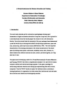
3 The graphical and force environment A new enhanced real-time graphical representation of the male urethra during the insertion of an endoscope is developed, see Figure 2.
Figure 2. Virtual male urethra during endoscope insertion. The study of typical endoscope paths revealed that the path center-line (CL) can be described by a parabola such as y = 0.13z2. The urethra’s cross-section is assumed to be circular with a constant radius at the undeformed state. The urethra’s surface is constructed by parametric cubic curves, which pass through certain points. The points are chosen to be equidistant, and are obtained by discretizing an orthogonal surface in both the peripheral and axial direction, see Figure 3a. The urethra is produced by orthogonal surface bending about its z axis to form a cylinder. This results in points P0, P5, P10, P15 and P20 coinciding with P4, P9, P14, P19 and P24, respectively. The points P0, …, P4 define the 1st peripheral section, the next five points define the 2nd peripheral section etc., see Figure 3a. The number of points that define each section is assigned to the parameter value n, while the number of sections is assigned to the parameter value w. In Figure 3a, n = 5 and w = 5.
(a) (b) Figure 3. (a) Simplified representation of the surface discretization (left) and the 1st peripheral section (right), for n = 5 and w = 5. (b) Non-deformed urethra for n=9, w=11 and arbitrary choice of radius. A parametric cubic curve must pass in real-time through points Pi in both directions. To produce smooth deformations, we must maintain at least tangent direction continuity at the interpolating points. Out of the parametric cubic curves, only the piecewise Bézier or Hermite interpolations
satisfy the above requirements. The Bézier form is chosen, because the tangent direction and magnitude are better depicted by means of control points. Each quadrilateral surface in Figure 3a, for example the one defined by points P6, P11, P12 and P7, is formed by four Bézier segments. The control points, CPi, that define the shape of the Bézier curves, are calculated by the Catmull-Rom method, which can represent closed curves with an appropriate choice of the first and last inner control points. The knot sequence is created using the Chord Length method, which produces small curvature variations giving smooth deformations. To obtain the geometry of Figure 1a, the centers of the peripheral sections must lie on the urethra CL. The section planes are rotated properly about the x axis, so that they are normal to the tangent of the parabola at the corresponding center position. Combining the piecewise Bézier interpolation in both directions, the geometry in Figure 3b is produced, where section centers are denominated as j = 0, …, (w-1) being equidistanced along z axis.
Figure 4. Basic sections and moving deformation for n=9, w=13. During endoscope insertion, the urethra is deformed due to three reasons. (a) The endoscope diameter is greater than the urethra’s, (b) the endoscope is rigid and (c) the endoscope position and orientation are variable. To be able to represent (a) accurately, the peripheral sections are divided into two sets. The first set, called set of basic sections, defines the global urethra geometry. Sections in this set are fixed and do not move along the urethra CL. The second set, called the moving deformation, represents the deformation of the urethra close to endoscope tip. These sections are spatially dense, move along the urethra CL, contain a basic section without displacing it along the urethra CL, and define the transition from the endoscope diameter to the urethra diameter during insertion. The endpoints of the axial Bézier segments within the moving deformation are chosen to form a sinusoidal profile, allowing for smooth attachment of the deformation on the endoscope and the urethra. The moving deformation passes through the basic sections without displacing them along the urethra CL. Implementation results are shown in Figure 4, where the propagation of the deformation of the urethra due to endoscope insertion with respect to the CL is shown.
(a)
(b) (c) Figure 5. (a)-(c) Deformation states.
The tissue view of the inner urethra wall is simulated by textures taken from medical databases. However, a texture may only cover flat quadrilateral surfaces. For this reason, each concave quadrilateral surface in Figure 3b is linearly approximated by a finite number of flat
quadrilateral surfaces using the Coons method. Texture is then applied separately to each one of the finite flat quadrilateral surfaces. The visual deformation of the urethra during endoscope insertion is implemented in OpenGL, which is a very portable and fast low-level 3D graphics and modeling API. A few deformation states, as shown by the virtual endoscope camera with n = 17 and w = 26, are depicted in Figure 5a-c. In this figure, the endoscope tip is (a) at the urethra entrance, (b) rotated upwards about the x axis, and (c) rotated left about the y axis. To use the simulator effectively, a simple and user-friendly GUI is needed that must (a) be easy to use, (b) be extendable in future simulated operations, (c) allow a user to choose the input device (haptic, if available, or keyboard for fast testing) and (d) display all the necessary numerical data. The latter is an optional feature, useful for trainees and trainers during playback and evaluation of a session. The developed GUI, see Figure 6, consists of three windows: (a) the Control, (b) the Graphics and (c) the Info window.
Figure 6. The graphical user interface. The Control window is divided into three fields. The first is the “Input Device” field, where the user chooses a haptic device or a keyboard. The second is the “Simulation Type” field, where the user chooses the kind of training simulation in which to participate. Currently, only the “Male Urethra Model” simulation is available, with two more, the “Tissue Model” and “Bone Model” under development. The third field is the “Control Buttons”, from which the user controls the session. A “Reset” button, resetting the values in the Info window and the graphics start position, is also available. The Graphics window contains the simulated male urethra, its deformations, and visual force feedback. The Info window displays important information about the training session and is also divided into three fields. The first field shows the elapsed time since the session start, the second shows the calculated forces/torques that are applied to a trainee’s hand by the haptic device, and the third shows the endoscope tip coordinates. The GUI code was developed on a Macintosh computer running OSX 10.4, using the Xcode and Interface Builder applications. In addition to the visual feedback described, the simulator must calculate the forces and torques that will be applied to a trainee’s hand through an endoscope attached to a haptic device. This is done using endoscope position feedback from the haptic device and a force model that represents the behavior of the involved tissues. Therefore, here this model is developed with focus in execution speed and basic elements that account for tissue spring-damper-resistance effects. The total resistance force along endoscope axis, Fre, is given by, [1]
Fre = F1 + F2 + F3
where F1 is Coulomb friction, F2 is viscous friction and F3 is wall resistance force. Since the endoscope does not move out of the human plane of symmetry y-z, only the projections of Fre on plane y-z, namely Fre,y and Fre,z need to be calculated. The Coulomb friction, F1, is calculated by
[2]
F1 = µ N (V! / V )sgn(V )
where V is the relative linear velocity between the endoscope and the tissue, µ is the friction coefficient associated with the normal to the endoscope axis force N, V|| is the component of V that is parallel to the endoscope axis, and sgn(V) is the sign of the velocity V. To compute the normal force N, a virtual spring model is established on each basic section. To increase the speed of force computations, springs between same and neighboring section points were ruled out, because the felt force here is mostly due to frictional effects and not to springiness along the urethra. The viscous friction F2 is calculated by, [3]
F2 = bv! V!
where bV|| is the viscous friction coefficient in the direction of V||, defined in [2]. Force F3 is a pure spring-type resistance, produced by the Coulomb friction springs on the basic sections in front of endoscope tip and calculated by summing the projections of spring forces, Fspr, along endoscope axis. A torque with three components, namely Tx, Ty and Tz acting about the x, y and z axes, respectively, is applied to the endoscope by the tissues. Dividing the urethra into two parts, of which the first is outside the body and free to move while the second is inside and constrained, then Tx appears when the endoscope is (a) in the constrained part and/or (b) off the parabolic CL (endoscope y-z translation). To compute the first part of Tx, a virtual rotational spring is placed at the endoscope tip to produce a torque due to x rotations. The spring constant is set to zero, when the endoscope is at the free part, and increases linearly according to endoscope position at the constrained part. The spring constant is then multiplied by the angle of the endoscope orientation with respect to the tangent of the parabolic CL at the deformation point. To calculate the torque Ty, a rotational spring producing torque about the y axis is assumed to exist at the endoscope tip. The spring constant is set to zero, when the endoscope is at the free part, and increases linearly according to endoscope position at the constrained part. The spring constant is then multiplied by the angle of the endoscope orientation about the y axis with respect to the human plane of symmetry, y-z. The torque Tz is the sum of two components: [4]
Tz = T1 + T2
T1 is Coulomb torque friction given by [5]
T1 = µ NV! (r / V )sgn(V ) , V" = ! r
where r is the endoscope radius, V is the component of V (see [2]) normal to endoscope axis and ω is the angular velocity about endoscope axis. T2 is viscous torque friction, [6]
T2 = b! !
where b ω is a viscous friction coefficient in the direction of ω.
4 The control environment The control environment consists of three processes running on two different platforms, communicating via Ethernet cards and TCP/IP protocol. The first process includes the control loop and the client side communication between the haptic device and the graphics, implemented on a PC/104 stack, which consist of a 233 MHz CPU module, a 24 MB solid state flash disk, an Ethernet communications module, two encoder polling input modules, and an analog output module, which drives the motor amplifiers, see Figure 7. The other two processes are running in parallel on the Virtual Model Computer, equipped with the OpenGL/C++
graphics library. The first includes the GUI and the real-time graphic environment depicting the endoscope camera view of the tissues and their deformations. The second includes the server side communication between the haptic device and the graphics as well as the force model. The PC/104 stack computes endoscope positions and orientations using encoder data, calculates endoscope velocities, and transmits positions, orientations and velocities to the Virtual Model Computer for force computations and graphics display. Desired forces/torques are transmitted to the PC/104, which commands motor amplifiers. The developed motor torques, through the haptic device, result in forces and torques applied to a trainee’s hand.
Figure 7. The control center. In order to control the parallel execution of the sub processes and to have a constant refresh rate in the second sub-process, QNX®, a real time operating system from QNX Software Systems Ltd., is employed.
5 Conclusions An enhanced real-time virtual graphical and haptic environment used in a medical training simulator is presented in this paper. The medical simulator is a training simulator for urological minimally invasive operations, and consists of a five-dof haptic device, the virtual graphical and force environment, and the control system. All parts of the simulator and appropriate experimental trials are described, and experimentation results are presented about the accuracy of the chosen force model method. It is expected that such a simulator will contribute to an ethical, efficient, and modern surgeon training. The visual system includes a real-time graphical representation of the deformable male urethra during endoscope insertion, while a mesh of piecewise Bézier interpolations was established for smooth deformations. An efficient real-time technique was developed to reproduce the camera depth-of-field effect supported by some recently introduced endoscopes, while tissue textures from medical databases were applied for realistic tissue rendering. A novel particle-based model was developed to compute in real-time the forces and torques fed to the haptics. Real-time graphics are updated using the Rendering Thread method and achieve a 13 fps refresh rate on a 2 GHz computer with the depth-of-field effect activated, and twice that when this feature is deactivated. It is expected that the developed environment will contribute to an ethical, efficient and modern surgeon training.
6 Acknowledgment This work is co-funded by the European Social Fund (75%) and National Resources (25%) – (EPEAEK II) – PYTHAGORAS.
7 References Basdogan C, Ho CH, Srinivasan MA, et al. (1998): Force Interactions in Laparoscopic Simulations: Haptic Rendering of Soft Tissues. In Proceedings of the Medicine Meets Virtual Reality, San Diego, CA, 1998, pp. 385-391. Baumann R., Maeder W., Glauser D., Clavel R. (1997): The PantoScope: A Spherical Remote-Center-of-Motion Parallel Manipulator for Force Reflection. In Proceedings of IEEE International Conference on Robotics and Automation, Albuquerque, NM, USA, Vol. 1, 718-723. Baur C., Guzzoni D., Georg O. (1998): Virgy: A Virtual Reality and Force Feedback Based Endoscopy Surgery Simulator. In Proceedings of The Medicine Meets Virtual Reality, San Diego, CA, USA, 110-116. Edwards JC, Luecke GR (1996): Physically Based Models for Use in a Force Feedback Virtual Environment. In Proceedings of the Japan/USA Symposium on Flexible Automation, Boston, MA, 1996, pp. 221-228. Hayward V., Gregorio P., Astley O., Greenish S., Doyon M. (1997): Freedom-7: A High Fidelity Seven Axis Haptic Device With Application To Surgical Training. In Proceedings of ISER-6 International Symposium on Experimental Robotics, 445-456. Kühnapfel U., Kuhn Ch., Hübner M., Krumm H.G., Maaß H., Neisius B. (1997): The Karlsruhe Endoscopic Surgery Trainer as an example for Virtual Reality in Medical Education. In: Minimally Invasive Therapy and Allied Technologies, pp. 122-125. Massie T., Salisbury J. K. (1994): The Phantom Haptic Interface: A Device for Probing Virtual Objects. In Proceedings of ASME Winter Annual Meeting, Symposium on Haptic Interfaces for Virtual Environment and Teleoperator Systems, Chicago, IL, USA, 295-301. Vlachos, K., Papadopoulos, E., and Mitropoulos, D. (2003) Design and Implementation of a Haptic Device for Urological Operations. IEEE Transactions on Robotics and Automation, 19, 5, 801-809. Vlachos, K., and Papadopoulos, E. (2006) Transparency Maximization Methodology for Haptic Devices. IEEE/ASME Transactions on Mechatronics, 11, 3, 249-255.