A Visual Language for Design Pattern Modelling and Instantiation. David
Maplesden, John Hosking and John Grundy. Department of Computer Science, ...
A Visual Language for Design Pattern Modelling and Instantiation David Maplesden, John Hosking and John Grundy Department of Computer Science, University of Auckland, Private Bag 92019 Auckland, New Zealand {dmap001,john,john-g}@cs.auckland.ac.nz Abstract We describe the Design Pattern Modelling Language, a notation supporting the specification of design pattern solutions and their instantiation into UML design models.
of a design pattern (eg class, method). When instantiated, this will be linked to objects from the object model. Name
1. Introduction Design patterns are a method of encapsulating the knowledge of experienced software designers in a human readable and understandable form. We describe the DPML (Design Pattern Modelling Language), a visual language for modelling design pattern solutions and their instantiations in OO designs of software systems.
Name
instanceName
instanceName
Interface
Attribute
Name
Name
inst anceName
Implementation
Binary Directed Relation
Name
Name
instanceName
instanceName
Operation
Interface with Dimensions
Name
2. Previous Work The proposed UML standard for modelling design patterns uses parameterised collaborations [1]. However, as these are constructed using similar concepts to object models, they are ust prototypical examples of an object model. A similar problem exists with the work of Florijn [2]. LePUS [3] uses monadic logic to express design pattern solutions and includes a visual notation. However, LePUS’ abstractions are difficult for average designers to work with. Lauder [[4]] extends UML to visually specify patterns using a 3-layer model. However, differentiation between their diagrams is unclear and it is not obvious why abstractions are made at one level and not another.
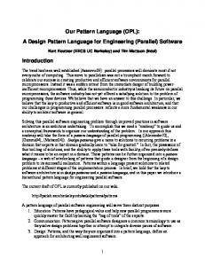
3. Overview of DPML DPML defines a notation for modelling design pattern solutions and solution instances within object models. DPML supports incorporation of patterns at design-time, rather than program coding, assuming that if patterns can be effectively incorporated into a UML class model then conversion to code is straightforward. The core concept of DPML is a design pattern specification diagram, the basic notation for which is shown in Fig. 1. DPML models design pattern solutions as a collection of participants; dimensions associated with the participants and constraints on the participants. A participant represents a structurally significant feature
instanceName
{A constraint imposed on an element}
Method
A Simple Constraint
Fig. 1: Basic DPML notation Dimensions specify that a participant can have a set of objects playing a role. The same dimension can be associated with different participants in a pattern and this specifies not only that these participants can have some multiple number of objects associated with them but that this number of objects is the same for both participants.
Declared_In
AbstractFactory Implements
createOps
concreteFactories
Realises
Return Type
Defined In
concreteCreateOps Creates
concreteProducts
Products Implements
Dimension Key factoriesDimension productsDimension
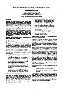
Fig. 2: Example specification of Abstract Factory.
Consider the Abstract Factory design pattern (Fig. 2). There are 6 main participants. The AbstractFactory interface declares the set of abstract create operations createOps that the concreteFactories will implement. The createOps operation represents a set of operations so has a dimension (productsDimension). A Declared_In relation between createOps and AbstractFactory implies that all methods linked to the createOps operation in an instantiation of the pattern must be declared in the object that is linked to the AbstractFactory interface. The concreteFactories implementation has dimension, factoriesDimension, to indicate it represents a number of concrete classes. The concreteCreateOps method represents all methods from the set of concreteFactories that implement one of the sets of createOps so is associated with dimensions factoriesDimension and productsDimension. The Products interface has productsDimension associated with it to imply there are the same number of abstract product interfaces as there are abstract createOps operations. The Return_Type relation implies each of the createOps operations has exactly one of the Products as its return type. The concreteProducts implementation has both productsDimension and factoriesDimension associated with it, as there is exactly one concreteProduct for each abstract product and concrete factory.
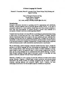
4. Design Pattern Instantiation A DPML Instantiation Diagram models design pattern instances and their realisation within object models. Instantiation diagrams are similar to specification diagrams; the basic symbols are the same shape, but the ‘proxy’ elements, representing the instantiated participants, have a dashed (or coloured) outline. Fig 3 shows an instantiation of Abstract Factory in a design for a GUI toolkit that allows programmers to create a GUI with windows, menus, icons, buttons etc. DPML was designed specifically to facilitate the provision of tool support. We have successfully
implemented a prototype DPML CASE tool. A screen dump showing the tool in use is shown in Fig. 4. AbstractFactory Declared_In
GUIFactory
Implements concreteFactories
createOps
MetalFactory SpaceFactory
createMenu createScrollBar createButton Realises
Return Type
Defined In
concreteCreateOps 6 bound elements Creates concretePro ducts
Products Menu ScrollBar Button
Implements
6 bound elements
Dimension Key factoriesDimension productsDimension
Fig. 3: Instantiation of the AbstractFactory pattern.
Acknowledgments The New Zealand PGSF, and the University of Auckland Research Committee supported this research.
References [1] Sunyé, G, Le Guennec, A, Jézéquel, J-M, “Design patterns application in UML”, ECOOP 2000 Proceedings of the 14th European conference on Object Oriented programming, LNCS 1850, pg 44-62, (2000). [2] Florijn, G Meijers, M van Winsen, P, “Tool support for object-oriented patterns”, ECOOP ‘97 – Proceedings of the 11th European conference on Object Oriented programming, LNCS 1241, pg 472-495, (1997). [3] Eden, AH, Hirshfeld, Y, Yehudai, A “LePUS – A declarative pattern specification language”, Technical report 326/98, department of Computer Science, Tel Aviv University, (1998). [4] Lauder, A, Kent, S “Precise Visual Specification of Design Patterns”, ECOOP’98 Workshop reader on OO technology, LNCS 1445, pg114-134, 1998.
Figure 4: A UML Class Diagram; a Design Pattern Specification Diagram; a Design Pattern Instantiation Diagram.