Figure 2: Classification of Design Patterns based on Relationship [1]. ........................... ...... Metsker in Design Pattern Java Workbook [23], adopts the notion that the intent of a design pattern is ..... specification. For specifying the data the algebra of abstract data type (ADT) is used. ...... Hemel Hempstead: Prentice Hall, 1992.
TOWARDS DESIGN PATTERN DEFINITION LANGUAGE (DPDL)
BY
SALMAN AHMAD KHWAJA
THESIS ADVISOR DR. MOHAMMAD ALSHAYEB
INFORMATION AND COMPUTER SCIENCE DEPARTMENT KING FAHD UNIVERSITY OF PETROLEUM & MINERALS
1
TABLE OF CONTENTS INTRODUCTION........................................................................................................... 15 Problem ..................................................................................................................... 17 Objectives ................................................................................................................. 18 Research Methodology ............................................................................................. 19 BACKGROUND ............................................................................................................. 20 Object Oriented Programming .................................................................................. 20 Class Based Model .................................................................................................... 20 Design Pattern in Object Oriented Programming ..................................................... 21 A DEFINITION OF DESIGN PATTERN ............................................................................... 23 HISTORY OF DESIGN PATTERNS ..................................................................................... 25 CLASSIFICATION OF DESIGN PATTERNS: ........................................................................ 26 Classification based on Purpose/Scope ..................................................................... 27 Classification based on Intent ................................................................................... 28 Classification based on Relationship among Design Patterns .................................. 29 Classification based on Organization: ...................................................................... 31 Enterprise Design Patterns ........................................................................................ 37 EXTENTENSIBLE MARKUP LANGUAGE (XML) .............................................................. 39 LITERATURE REVIEW .............................................................................................. 43 LANGUAGES BASED ON FORMAL MATHEMATICAL LOGIC ............................................. 44 LePUS ....................................................................................................................... 44 eLePUS ..................................................................................................................... 45 2
LOTOS ...................................................................................................................... 47 DisCo ........................................................................................................................ 49 BPSL ......................................................................................................................... 50 LANGUAGES BASED ON UML ........................................................................................ 53 RBML ....................................................................................................................... 53 DPML ....................................................................................................................... 55 LANGUAGES BASED ON GENERAL PROGRAMMING LANGUAGES .................................... 58 SPINE ....................................................................................................................... 58 DESIGN PATTERNS ..................................................................................................... 62 INTRODUCTION .............................................................................................................. 62 Creational Design Patterns ........................................................................................ 62 Structural Design Patterns......................................................................................... 62 Behavioral Design Patterns ....................................................................................... 63 ADAPTER ....................................................................................................................... 63 Intent ......................................................................................................................... 63 Motivation ................................................................................................................. 64 Applicability ............................................................................................................. 65 Structure .................................................................................................................... 65 Collaborations ........................................................................................................... 66 Consequences ............................................................................................................ 66 FACTORY METHOD ........................................................................................................ 67 Intent ......................................................................................................................... 67 Motivation ................................................................................................................. 67
3
Applicability ............................................................................................................. 68 Structure .................................................................................................................... 68 Collaborations ........................................................................................................... 69 Consequences ............................................................................................................ 69 MEDIATOR ..................................................................................................................... 70 Intent ......................................................................................................................... 70 Motivation ................................................................................................................. 70 Structure .................................................................................................................... 71 Applicability ............................................................................................................. 72 Collaborations ........................................................................................................... 73 Consequences ............................................................................................................ 73 DESIGN PATTERN DEFINITION LANGUAGE (DPDL) ....................................... 74 OBJECTIVES OF DPDL ................................................................................................... 74 Objective ................................................................................................................... 74 DPDL Design Objectives .......................................................................................... 74 DPDL SCHEMA .............................................................................................................. 76 DESIGN PATTERN ATTRIBUTES ...................................................................................... 79 STRUCTURALATTRIBUTES ............................................................................................. 82 Philosophy of Structural Attributes Model ............................................................... 83 Classes Element ........................................................................................................ 84 Class Element............................................................................................................ 85 Operations Element ................................................................................................... 89 Function Element ...................................................................................................... 89
4
Objects Element ........................................................................................................ 97 Object Element.......................................................................................................... 97 Relationship Element .............................................................................................. 101 Relation Element ..................................................................................................... 101 BEHAVIORALATTIBUTES.............................................................................................. 104 Overview of BehavioralAttributes Element............................................................ 105 SetObject Element .................................................................................................. 106 Call Element............................................................................................................ 107 Create Element ........................................................................................................ 110 Loop Element .......................................................................................................... 112 Condition Element .................................................................................................. 113 Common Attributes................................................................................................. 114 TOOLS ........................................................................................................................... 117 DPDL CLASS TOOL ..................................................................................................... 118 DPDL Class Tool Features ..................................................................................... 119 Creating Class Diagram from DPDL Class Tool .................................................... 121 Other Options in DPDL Class Tool ........................................................................ 123 Current Limitation of DPDL Class Tool ................................................................ 124 DPDL QTOOL ............................................................................................................. 125 DPDL QTool Feature .............................................................................................. 126 Creating Sequence Diagram in QTool .................................................................... 128 Current Limitation of QTool ................................................................................... 129 VERIFICATION & VALIDATION ........................................................................... 131
5
DESIGN PATTERN INSTANCES ...................................................................................... 131 Adapter Design Pattern ........................................................................................... 131 Structural Description in DPDL.......................................................................... 133 Behavioral Description in DPDL ........................................................................ 139 Mediator Design Pattern: ........................................................................................ 142 Strucutral Description in DPDL.......................................................................... 144 Behavioral Description in DPDL ........................................................................ 150 Factory Method Design Pattern .............................................................................. 153 Structural Description in DPDL.......................................................................... 154 Behavioral Description in DPDL ........................................................................ 160 DESIGN PATTERN TEMPLATES ..................................................................................... 163 Adapter Design Pattern Template ........................................................................... 164 Structrual Description in DPDL.......................................................................... 164 Behavior Description in DPDL........................................................................... 168 Mediator Design Pattern Template. ........................................................................ 169 Structural Description in DPDL.......................................................................... 170 Behavioral Description in DPDL ........................................................................ 174 Factory Design Pattern Template............................................................................ 176 Structural Description in DPDL.......................................................................... 177 Behavioral Description in DPDL ........................................................................ 181 CONCLUSION & FUTURE WORK.......................................................................... 182 REFERENCES .............................................................................................................. 184
6
LIST OF FIGURES Figure 1: OO development life-cycle and patterns. [13] .................................................. 23 Figure 2: Classification of Design Patterns based on Relationship [1]. ........................... 30 Figure 3: Design Pattern Elements classification ............................................................. 31 Figure 4: Wrapper Design Patterns ................................................................................... 32 Figure 5: Inheritance Design Patterns ............................................................................... 33 Figure 6: Wrapper with Inheritance Design Pattern ......................................................... 33 Figure 7: Recursive Composition Design Pattern ............................................................. 34 Figure 8: Cloud Design Pattern......................................................................................... 36 Figure 9: Miscellaneous Design Pattern ........................................................................... 37 Figure 10: Structure of Factory Method as defined in eLePUS........................................ 46 Figure 11: Collaboration of Factory Method as defined in eLePUS ................................ 46 Figure 12: Behavioral Specification of Composite Pattern in LOTOS ............................ 48 Figure 13: Class Diagram of Observer Pattern [39] ......................................................... 51 Figure 14: BPSL Specification of Observer Pattern [39] ................................................. 52 Figure 15: AbstractFactory design pattern in DPML [4] .................................................. 57 Figure 16: Adapter Design Pattern [1] .............................................................................. 65 Figure 17: Factory Method Design Pattern [1] ................................................................. 68 Figure 18: Mediator Design Pattern [1] ............................................................................ 72 Figure 19: DPDL High Level Schema .............................................................................. 78 Figure 20: DPDL's Structural Attributes .......................................................................... 82 Figure 21: Attributes of Class Element of DPDL ............................................................. 85 Figure 22: Attributes of Function Element in DPDL........................................................ 90 7
Figure 23: Example of forEach in Function. .................................................................... 95 Figure 24: Example of inEach for Function ..................................................................... 96 Figure 25: Attributes of Object Element in DPDL ........................................................... 97 Figure 26: Attributes of Relation Element in DPDDL ................................................... 101 Figure 27: DPDL's Behavioral Attributes ....................................................................... 105 Figure 28: SetObect Element's Attributes in DPDL ....................................................... 106 Figure 29: Call Element's Attributes in DPDL ............................................................... 108 Figure 30: Create Element's Attributes in DPDL ........................................................... 110 Figure 31: Loop Element's Attributes in DPDL ............................................................. 112 Figure 32: Condition Element's Attributes in DPDL ...................................................... 113 Figure 33: DPDL Class Tool .......................................................................................... 119 Figure 34: DPDL Class Tool View Menu ...................................................................... 120 Figure 35: File Menu Options ......................................................................................... 121 Figure 36: DPDL Class Tool Open DialogBox .............................................................. 122 Figure 37: Class Diagram in DPDL Class Tool.............................................................. 123 Figure 38: Option for generating Source Code in DPDL Class Tool ............................. 124 Figure 39: QTool, the Sequence Diagram Generator ..................................................... 126 Figure 40: File Menu options in QTool .......................................................................... 127 Figure 41: Edit Option in QTool ..................................................................................... 128 Figure 42: QTool Open DialogBox ................................................................................ 129 Figure 43: DPDL of Adapter Design Pattern .................................................................. 133 Figure 44: Class in DPDL for Adapter Design Pattern................................................... 134 Figure 45: Operations in DPDL for Adapter Design Pattern .......................................... 135
8
Figure 46: Objects in DPDL for Adapter Design Pattern ............................................... 136 Figure 47: Relationships in DPDL for Adapter design pattern....................................... 137 Figure 48: Class Diagram of Adapter Design Pattern through DPDL............................ 138 Figure 49: Class Diagram By Altova .............................................................................. 139 Figure 50: Behavioral Structure in DPDL for Adapter Design Pattern .......................... 140 Figure 51: Sequence Diagram by QTool from Adapter DPDL ...................................... 141 Figure 52: Sequence Diagram in Altova of Adapter Design Pattern .............................. 142 Figure 53: Mediator Design Pattern's DPDL .................................................................. 143 Figure 54: Classes Section of DPDL of Mediator Design Pattern.................................. 144 Figure 55: Funtion Section of DPDL of Mediator Design Pattern ................................. 145 Figure 56: Function Section of DPDL of Mediator Design Pattern ............................... 146 Figure 57: Objects Section of DPDL of Mediator Design Pattern ................................. 147 Figure 58: Relationships Section of DPDL of Mediator Design Pattern ........................ 148 Figure 59: Class diagram of Mediator Design Pattern by DPDL Class Tool ................. 149 Figure 60: Class diagram of Mediator Design Pattern by ALTOVA ............................. 150 Figure 61: Behavior Structure of Mediator Design Pattern in DPDL ............................ 151 Figure 62: Sequence Diagram of Mediator's DPDL by QTool....................................... 152 Figure 63: Sequence Diagram for Mediator generated by ALTOVA ............................ 153 Figure 64: Overview of Factory Method Design Pattern's DPDL .................................. 154 Figure 65: Classes Section of DPDL of Factory Design Pattern .................................... 155 Figure 66: Operations Section of DPDL of Factory Design Pattern .............................. 156 Figure 67: Objects Section of DPDL of Factory Design Pattern .................................... 157 Figure 68: Relationships Section of DPDL of Factory Design Pattern .......................... 158
9
Figure 69: Class Diagram of Factory Method using DPDL ........................................... 159 Figure 70: Class Diagram of Factory Method Design pattern By ALTOVA ................. 160 Figure 71: Behavior Description of Factory Method Design Pattern in DPDL ............. 161 Figure 72: Sequence Diagram of Factory Method Design Pattern using DPDL ............ 162 Figure 73: Sequence Diagram of Factory Method by ALTOVA. .................................. 163 Figure 74: Overview of Adapter Design Pattern Template's DPDL .............................. 164 Figure 75: Classes of Adapter Design Pattern Template's DPDL .................................. 165 Figure 76: Operation of Adapter Design Pattern Template's DPDL .............................. 166 Figure 77: Objects of Adapter Design Pattern Template's DPDL .................................. 167 Figure 78: Relationships of Adapter Design Pattern Template's DPDL ........................ 168 Figure 79: Behavioral Descriptio of Adapter Design Pattern Template's DPDL ........... 168 Figure 80: Overview of of Mediator Design Pattern Template's DPDL ........................ 169 Figure 81: Classes of Mediator Design Pattern Template's DPDL ................................ 170 Figure 82: Operation of Mediator Design Pattern Template's DPDL ............................ 171 Figure 83: Objects of Mediator Design Pattern Template's DPDL ................................ 172 Figure 84: Relationships of Mediator Design Pattern Template's DPDL ....................... 173 Figure 85: Behavioral Descriptions of Mediator Design Pattern Template's DPDL ...... 175 Figure 86: Overview of Factory Method Design Pattern Template's DPDL .................. 176 Figure 87: Classes of Factory Method Design Pattern Template's DPDL ..................... 177 Figure 88: Operations of Factory Method Design Pattern Template's DPDL ................ 178 Figure 89: Objectof Factory Method Design Pattern Template's DPDL ........................ 179 Figure 90: Relationships of Factory Method Design Pattern Template's DPDL ............ 179
10
Figure 91: Behavioral Description of Factory Method Design Pattern Template's DPDL ................................................................................................................................. 181
11
LIST OF TABLES Table 1: Classification of Design Pattern on Scope\Purpose basis [1]. ............................ 27 Table 2: Classification of Design Pattern on Intent Basis [23] ......................................... 28 Table 3: Mark Grand Design Pattern Categorization ...................................................... 37 Table 5: History of XML .................................................................................................. 40 Table 4: Design Pattern Languages feature comparison................................................... 60
12
ABSTRACT Full Name
: Salman Ahmad Khwaja
Thesis Title
: Towards Design Pattern Definition Language
Major Field
: Information and Computer Science
Date of Degree : June, 2010 Design Patterns are rapidly gaining acceptance in the software industry not only as reusable constructs for the software development but also as the documentation and comprehension of the architectural design of a software system. They provide proven solutions for a set of recurring design problems. Therefore using them improves both quality and time to market of a software project. Currently, design pattern languages have mostly described design patterns using a combination of natural language or UML-style diagrams or complex mathematical or logic based formalisms, which the average programmer finds difficult to understand. Therefore, in this research we propose a design pattern definition language (DPDL) which can be used for sharing of design pattern implementation details among developers. It also has the flexibility of defining the design pattern in a very generic term to be used as a template for the design pattern, which can then be used for verification and identification of design patterns. Moreover, a tool as a proof of concept of DPDL has also been developed to verify and validate the proposed language.
13
هلخص الرسالة االسن :سلواى احود خواجة
عنواى الرسالة :
نحو تصوين لغة تعريف انواط التصوين
التخصص:
علوم الحاسب االلي
تاريخ الرسالة : فً االًنت االخٍشة ,اخزث انًبط انتصًٍى تكتسب قبٌل ًاسع ً سشٌع فً يجبل انتبد انبشيجٍبث , فيً عببسة عن قٌانب تستخذو فً ًصف حم عبو نًشكالث يتكشسة انحذًث فً ىنذست انبشيجٍبث . ً بيزا فيً تعتبش ًحبئق تسبعذ عهى فيى انتصًٍى انًعًبسي ننظى انبشيجٍبث
ً ,اٌضب استخذاييب
ٌعًم عهى تحسٍن نٌعٍت انبشيجٍبث ً تسيٍم عًهٍت تسٌٌق انًشبسٌع انبشيجٍت. حبنٍبٌ ,تى ًصف انًبط انتصًٍى ببستخذاو يضٌذ ين انهغبث انحٍت ً اشكبل ىنذسٍت ً يخططبث ً سيٌص سٌبضٍت ً ينطقٍت ً ,ىً تًخم عبئب عهى انًبشيذ انًبتذئ فً فيًيب ً انتعبيم يعيب ً .نزنك فً ىزه انشسبنت نقتشح تعشٌف نغت نٌصف انًبط انتصًٍى ( )DPDLحٍج ٌتى استخذاييب نتببدل تفبصٍم ًحبئق انًبط انتصًٍى بٍن يطٌسٌن نظى انًعهٌيبث
.كًب نذٌيب انًشًنت فً تحذٌذ نًظ
انتصًٍى بشكم عبو الستخذايو كنًٌرد ننًظ انتصًٍى ً ببنتبنً ًٌكن استخذاييب نهتحقق ً تحذٌذ انًبط انتصًٍى ً .عالًة عهى رنك فقذ تى اٌضب تصًٍى بشيجٍبث يتقذيت نهتحقق ين صحت ً صٍغت انهغت انًقتشحت.
14
CHAPTER 1 INTRODUCTION Design Patterns are rapidly gaining acceptance in the software industry, not only as reusable constructs for the software development but also as the documentation and comprehension of the architectural design of a software system. Although many software teams and companies maintain their own set of design patterns, automation support for the utilization of design pattern is still very limited. The complexity of a software problem can only be managed by breaking down of the problem into smaller sub-problems. Even the most complex systems are built by using smaller "parts", influencing the overall design directly or indirectly. A part can be anything from an entire sub-system to a specific component, native to the language or otherwise, that requires the need for a specific design. Such parts may in turn be built using even smaller parts and so forth and need to communicate to function, as a whole. The key to any viable design is to identify the relevant parts, their functionality and their interaction, but this is not a trivial matter. This is known as the divide and conquers technique. Design patterns provide knowledge in an accessible way to provide reusable solutions to these sub-problems. Patterns are normally described informally in the literature, generally using natural language narrative, together with some sort of graphical notation, which makes it difficult to give any meaningful certification of pattern-based software. Patterns in the Gang of Four catalogue[1] are described using a consistent format which is based on an extension of the object modeling technique (OMT) [2]. This form of presentation gives a very good
15
intuitive picture of the patterns, but it is not sufficiently precise to allow a designer to conclusively demonstrate that a particular problem matches a specific pattern or that a proposed solution is consistent with a particular pattern. Some other benefits of software design patterns are: (1) software design patterns enable large scale reuse of software [1]; (2) software design patterns captures the expert knowledge and design trade-offs and make expertise widely available [1]; (3) software design patterns techniques are used for making code more flexible by making it meet certain specific criteria [1]; (4) each software design Pattern is designed for achieving a particular purpose; (5) They can reduce development time as known solutions are used instead of reinventing the wheel; (6) because software design patterns are extensively used across different solutions, another benefit is that they are known solutions that are tried and tested; and (7) design patterns make the communication of development teams easier. It is difficult to be certain that patterns themselves are meaningful and contain no inconsistencies. In some cases, descriptions of patterns are intentionally left loose and incomplete to ensure that they are applicable in a range as wide as possible. This reduces understanding and interpretation upon appropriate patterns usage. Describing the pattern in a more formal description could help alleviate these problems but at the same time make them harder to understand and implement them during the software development. Currently, design pattern languages have mostly described design patterns using a combination of natural language, UML-style diagrams [3, 4], complex mathematical or logic based formalisms [5-7], which the average programmer finds difficult to
16
understand. This leads to complications in incorporating design patterns effectively into the design of new software. The motivation for using design patterns in the software development is to improve the quality of software by improving its structure. The motivation for formalizing design patterns is to improve their quality and make them easier to understand and implement them in the application. In the case of design pattern language, this means having a language which reduces the problems that arise due to their too loose description or too much formal description. In other words, a design pattern language which have the flexibility of defining the design pattern in a very generic term by the software designers, which can cover all the different instances of that design pattern. Also at the same time the design pattern language should provide the capability to define the design pattern in such a way which can help software developers to create an exact replica of the design pattern during implementation.
Problem
As the use of the software design patterns is on the rise, there is more demand to have a language that provides support for a consistent, unambiguous and a simple way of sharing design patterns knowledge. When many teams are working independently on software, ambiguous and unclear communication can cause serious bugs in the system [8]. The communication should be in simple terms and easily understandable by all levels of software engineers. Several design pattern languages exist; however, they have few shortcomings. Languages like LePUS [5] and eLePUS [6] are based on formal mathematical techniques which 17
makes it hard for all programmers to understand and use them. These languages concentrate on structural aspect of the design pattern and do not convey semantics of the underlying design patterns. RBML [3] and DPML [4] languages are based on UML notation; UML based modeling techniques are still considered as semi-formal [9]. These languages also lack the support for pre and post conditions which sometime require textual support. Therefore, there is a need for a new design pattern specification language that uses the distinctive characteristics of Extensible Markup Language (XML), JavaScript Object Notation (JSON) or other commonly used representation languages. The language should be simple, extensible and interoperable. These characteristics can satisfy some new requirements like platform independence, textual and graphical support and easy integration into Integrated Development Environments for modeling tools and technologies in the age of the Internet/Web.
Objectives
The main objective of this research is to develop a design pattern definition language (DPDL) which is platform independent, usable and understandable by all levels of software engineers. The language should exhibit the following characteristics: i.
The language should be unambiguous; pattern definition should have or exhibit a single clearly defined meaning.
ii.
The language should be easily extendible;
the language should be able to
handle different variation of same design pattern.
18
iii.
The language should be based on existing technologies, as much as possible, to have wider and faster acceptance.
iv.
The language should be able to produce graphical/UML output.
Research Methodology
In order to achieve our objectives, the following approach will be taken: i.
Analyze the existing design patterns languages and their structural characteristics.
ii.
Define properties for the target design pattern language by analyzing the characteristics of the existing languages and the objective of the proposed design pattern language. .
iii.
Select the appropriate representation language for the new proposed design patterns language. .
iv.
Define a meta-model for the design patterns definition language.
v.
Develop a tool to verify and validate the structural and behavioral conformance and integrity of the design patterns described using DPDL by converting the design patterns into UML diagrams.
vi.
Finalize and publish the results.
19
CHAPTER 2 BACKGROUND
Object Oriented Programming
The general lack of consensus regarding fundamental Object Oriented (OO) concepts is clearly illustrated by a recent survey of existing literature related to OO development performed by Armstrong [10]. Two hundred and thirty nine articles, books, and conference proceedings related to OO development were examined by Armstrong trying to identify the essential elements of OO development. Thirty nine concepts were identified, but only eight of these were utilized by the majority of the sources reviewed. Armstrong states that the lack of consensus may be because we do not yet thoroughly understand thse fundamental concepts that define the OO approach. The idea behind object-oriented programming is that a computer program is composed of a collection of individual units, or objects, as opposed to a traditional view in which a program is little more than a list of instructions to the computer. Each object is capable of receiving messages, processing data, and sending messages to other objects. In this way, messages can be handled, as appropriate, by one chunk of code or by many in a seamless way.
Class Based Model
Object-oriented design [11] is the construction of software systems as a structured collection of classes. The emphasis is on structuring a system around the types of objects 20
it manipulates (not the functions it performs on them) and on reusing whole data structures together with the associated operations (not isolated routines). Classes are designed as units which are interesting and useful on their own, independently of the systems to which they belong; therefore they can be reused by many different systems. Software construction is thus viewed as the assembly of existing classes, not as a topdown process starting from scratch [12]. The object oriented approach attempts to manage the system complexity by abstracting out knowledge and encapsulating it within interacting objects, which are instances of specific classes [13]. Hence, a part can be viewed as a single object or a collection of interacting objects delivering a specific functionality. If we view a part as a design problem to be solved, regardless of the approach chosen, it is likely that others have already solved a similar problem in a satisfactory manner. If we can utilize this knowledge, the quality of the system may be improved. One of the approaches is to identify reoccurring design problems and their well-proven solutions are; to use software design patterns.
Design Pattern in Object Oriented Programming
A technique often utilized by expert designers is to reuse solutions that have worked for them in the past. When they find a good solution, they use it again and again. Such experience is part of what makes them experts. Consequently, one can find recurring patterns of classes and communicating objects in many object-oriented systems [1]. These patterns solve specific design problems and make object-oriented designs more flexible, elegant and ultimately reusable.
21
A design pattern is an abstraction of practical experience and empirical knowledge, but it is also a description of the problem it addresses and a solution to it [14, 15]. While the design pattern provides a canonical solution to the described problem, human interaction and interpretation is required to apply the solution in different contexts. Patterns are uniquely named and written in a consistent format that allows designers, developers, and others to communicate using a common vocabulary. Related patterns are grouped in collections, or ideally languages. Design patterns can facilitate the entire design and development process because they express ideas and solutions founded in experience traditional methodologies cannot. They communicate architectural ideas in a consistent high-level language. As the design phase is so central to OO development, it is paramount that the design is sound and durable. While the OO method may guide the design process, it cannot offer the specific knowledge represented by a pattern. Patterns known by the designer can be used as a tool in the design process because they offer proven solutions to common problems, which ideally heighten the quality of the design. Part of the pattern knowledge is describing the objects and their relationships relevant for the given scenario, thereby making the job of the designer a little easier. As a benefit, the application of well-known patterns will probably make the design seem more familiar to other designers as well. Figure 1 illustrates the OO software development life-cycle commonly used and the relation to patterns. It does not show the deployment and evaluation phases.
22
Figure 1: OO development life-cycle and patterns. [13]
A DEFINITION OF DESIGN PATTERN A design pattern is a pattern whose form is described by means of software design constructs, for example objects, classes, inheritance, aggregation and use-relationship [16]. In "Understanding and Using Patterns in Software Development" [16], Dirk Riehle and Heinz Zullighoven gave a nice definition of the term "pattern" which is very broadly applicable: A pattern is the abstraction from a concrete form which keeps recurring in specific nonarbitrary contexts. So according to Dirk and Zullighoven, the notion of a pattern is "geared toward solving problems in design." More specifically, the concrete form which recurs is that of a solution to a recurring problem. But a pattern is more than just a battle-proven solution to a recurring problem. The problem occurs within a certain context, and in the presence of numerous competing concerns. The proposed solution involves some kind of structure which balances these concerns, or "forces", in the manner most appropriate for the given context. Using the pattern form, the description of the solution tries to capture the 23
essential insight which it embodies, so that others may learn from it, and make use of it in similar situations. The pattern is also given a name, which serves as a conceptual handle, to facilitate discussing the pattern and the jewel of information it represents. So a definition which more closely reflects its use within the patterns community is given by Brad [17]: A pattern is a named nugget of instructive information that captures the essential structure and insight of a successful family of proven solutions to a recurring problem that arises within a certain context and system of forces. A slightly more compact definition which can be extracted from the above definition also given by Brad is [17]: A pattern is a named nugget of insight that conveys the essence of a proven solution to a recurring problem within a certain context amidst competing concerns. Patterns are usually concerned with some kind of architecture or organization of constituent parts to produce a greater whole. Richard Gabriel, author of Patterns of Software: ―Tales From the Software Community‖ [18], provides a clear and concise definition of the term pattern in the Patterns Definitions section of the Patterns Home Page: Each pattern is a three-part rule, which expresses a relation between a certain context, a certain system of forces which occurs repeatedly in that context, and a certain software configuration which allows these forces to resolve themselves. As an element in the world, each pattern is a relationship between a certain context, a certain system of forces which occurs repeatedly in that context, and a certain spatial configuration which allows these forces to resolve themselves.
24
As an element of language, a pattern is an instruction, which shows how this spatial configuration can be used, over and over again, to resolve the given system of forces, wherever the context makes it relevant. The pattern is, in short, at the same time a thing, which happens in the world, and the rule which tells us how to create that thing, and when we must create it. It is both a process and a thing; both a description of a thing which is alive, and a description of the process which will generate that thing, Jim Coplien writes in Software Patterns [19]: “I like to relate this definition to dress patterns. I could tell you how to make a dress by specifying the route of a scissors through a piece of cloth in terms of angles and lengths of cut. Or, I could give you a pattern. Reading the specification, you would have no idea what was being built or if you had built the right thing when you were finished. The pattern foreshadows the product: it is the rule for making the thing, but it is also, in many respects, the thing itself.” So it shows that a pattern involves a general description of a recurring solution to a recurring problem replete with various goals and constraints. But a pattern does more than just identify a solution; it also explains why the solution is needed!
HISTORY OF DESIGN PATTERNS In 1987, Ward Cunningham and Kent Beck were working with Smalltalk and designing user interfaces. They decided to use some of Alexander's [20] ideas to develop a small five pattern language for guiding novice Smalltalk programmers. They wrote up the results and presented them at OOPSLA'87 in Orlando in the paper "Using Pattern Languages for Object-Oriented Programs‖ [21].
25
Soon afterward, Jim Coplien began compiling a catalog of C++ idioms (which are one kind of pattern) and later published them as a book in 1991, ―Advanced C++ Programming Styles and Idioms‖ [22]. From 1990 to 1992, various members of the Gang of Four met and compiled a catalog of patterns. Discussions of patterns abounded at OOPSLA'91 at a workshop given by Bruce Andersen (which was repeated in 1992). Some pattern advocates participated in these workshops, including Jim Coplien, Doug Lea, Desmond D'Souza, Norm Kerth, Wolfgang Pree, and others. In August 1993, Kent Beck and Grady Booch sponsored a mountain retreat in Colorado, the first meeting of what is now known as the Hillside Group. Another patterns workshop was held at OOPSLA'93 and then in April of 1994, the Hillside Group met again (this time with Richard Gabriel added to the fold) to plan the first Pattern Languages of Programs (PLoP) conference. Shortly thereafter, the Gang of Four‘s Design Patterns book [1] was published. Journal of Object Oriented Programming named it (in their September 1995 issue) both the best Object Oriented (OO) book of 1995, and the best OO book of all time. In 1998, the Gang of Four were awarded Dr Dobbs Journal 1998 Excellence in Programming Award.
CLASSIFICATION OF DESIGN PATTERNS: Design Patterns are classified in many different ways. The most commonly used classifications are discussed below:
26
Classification based on Purpose/Scope The classification is based on two criteria, purpose and scope. The purpose criterion deals with the kind of problem the pattern solves. The scope criterion groups the patterns in class and object patterns. Class patterns are based on relationships between classes, mainly inheritance structures. Object patterns dynamically let objects reference each other [1].
Scope \ Purpose
Creational
Structural
Behavioral
Class
Factory Method
Adapter (class)
Interpreter Template method
Object
Abstract Factory
Adapter (object)
Chain of Responsibility
Builder
Bridge
Command
Prototype
Composite
Iterator
Singleton
Decorator
Mediator
Façade
Memento
Flyweight
Observer
Proxy
State Strategy Visitor
Table 1: Classification of Design Pattern on Scope\Purpose basis [1].
27
The purpose criterion sorts the patterns in three groups: Creational, Structural and Behavioral. Creational patterns deals with object creation. Structural patterns deal with compositions of objects and classes. Behavioral patterns are used to distribute responsibility between classes and objects.
Classification based on Intent Metsker in Design Pattern Java Workbook [23], adopts the notion that the intent of a design pattern is usually expressed as the need to go beyond the ordinary facilities that are built into programming Language. For example, Java has plentiful support for defining the interfaces that a class implements. But if you want to adapt a class's interface which cannot be changed to meet the needs of a legacy client which also cannot be changed, you need to apply the ADAPTER pattern. In this way the intent of the ADAPTER pattern goes beyond the interfacing facilities built into Java. Categorizing patterns by intent does not mean that each pattern support only one type of intent. But the Pattern is categorized under the primary intent. INTENT INTERFACES
PATTERNS ADAPTER, FACADE, COMPOSITE, BRIDGE
SINGLETON, OBSERVER, MEDIATOR, PROXY, CHAIN OF RESPONSIBILITY, RESPONSIBILITY FLYWEIGHT CONSTRUCTION
BUILDER, FACTORY METHOD, ABSTRACT FACTORY, PROTOTYPE, MEMENTO
OPERATIONS
TEMPLATE METHOD, STATE, STRATEGY, COMMAND, INTERPRETER
EXTENSIONS
DECORATOR, ITERATOR, VISITOR
Table 2: Classification of Design Pattern on Intent Basis [23]
28
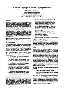
Classification based on Relationship among Design Patterns In addition to the above mentioned classification, there is another classification based on the relationships between the design patterns [17]. Each pattern has a ―related patterns‖ section in their description. Most of these relations between design patterns are assembled in Figure 2 below. Figure 2 does not show the relationship between Adapter, Proxy and Bridge design patterns as no connecting relationship is found between them and other patterns or even among themselves.
29
Momento
Proxy
Saving state of iteration
Adapter
Builder
Bridge
Iterator
Avoiding hysteresis Creating composites
Enumerating children
Decorator
Command
Composed using Adding responsibilities To the objects
Composite
Sharing composites
Avoiding traversals
Changing skin Versus guts
Defining grammer
Flyweight
Adding operations
Defining the chain
Visitor
Sharing strategies
Strategy
Sharing states Sharing Terminal Symbols
Interpreter
Mediator
State
Defining algorithm step
Chain Of Responsibility
Adding Operations
Complex Dependency management
Template Method
Observer
Often uses
Prototype Factory Method
Configuring Factory Dynamically Implement using
Abstract Factory Single Instance
Facade Single Instance
Singleton
Figure 2: Classification of Design Patterns based on Relationship [1].
30
Classification based on Organization: Vince Huston has formulated a classification of design patterns based on the organizational structure of the classes. This has resulted in a very unique shape which is just like periodic table used in chemistry. The Figure 3 below shows this:
Figure 3: Design Pattern Elements classification Gang of four design patterns [1] are also categorized according to the structural similarities. There are 6 categories created by Vince Huston, which are listed below with examples.
Wrapper Design Patterns The design patterns belonging to wrapper design patterns can also be represented by leftright symbols. They can also be distinguished by ―has a‖ relationship. They include following design patterns
31
Adapter: Wrap a legacy object that provides an incompatible interface with an object that supports the desired interface Facade: Wrap a complicated subsystem with an object that provides a simple interface Proxy: Wrap an object with a surrogate object that provides additional functionality Wrapper design patterns can be represented graphically as shown in Figure 4:
Figure 4: Wrapper Design Patterns
Inheritance Design Patterns: These design patterns promote interface to a base class and bury implementation alternatives in derived classes. They can be represented by up-down symbol. Graphical representation of these design patterns are shown in Figure 5. Strategy: defines algorithm interface in a base class and implementations in derived classes. Factory Method: defines "createInstance" placeholder in the base class, each derived class calls the "new" operator and returns an instance of itself Visitor: defines "accept" method in first inheritance hierarchy, defines "visit" methods in second hierarchy can also be called as "double dispatch".
32
Figure 5: Inheritance Design Patterns
Wrapper with Inheritance Design Patterns: These design patterns wraps an inheritance hierarchy. It can be seen in Figure 6 that two separate structures are linked together:
Figure 6: Wrapper with Inheritance Design Pattern The example of Wrapper with Inheritance design patterns are: Builder: The "reader" delegates to its configured "builder", each builder corresponds to a different representation or target
33
State: The FiniteStateMachine delegates to the "current" state object, and that state object can set the "next" state object Bridge: The wrapper models "abstraction" and the wrappee models many possible "implementations", the wrapper can use inheritance to support abstraction specialization Observer: The "model" broadcasts to many possible "views", and each "view" can dialog with the "model"
Recursive Composition Design Patterns These design patterns have recursive calls through which they handle queries. Figuratively they can be shown as in Figure 7
Figure 7: Recursive Composition Design Pattern The examples of these design patterns are Composite: Derived Composites contain one or more base Components, each of which could be a derived Composite
34
Decorator: A decorator contains a single base Component, which could be a derived ConcreteComponent or another derived Decorator Chain of Responsibility: Defines "linked list" functionality in the base class and implement "domain" functionality in derived classes Interpreter: Maps a domain to a language, the language to a recursive grammar, and the grammar to the Composite pattern
Cloud Design Patterns These design patterns encapsulate methods. The examples for these design patterns are Command: Encapsulates an object, the method to be invoked, and the parameters to be passed behind the method signature "execute" Iterator: Encapsulates the traversal of collection classes behind the interface "first, next, isDone" Mediator: Decouples peer objects by encapsulating their "many to many" linkages in an intermediary object Memento: Encapsulates the state of an existing object in a new object to implement a "restore" capability Prototype: Encapsulates use of the "new" operator behind the method signature "clone" ... clients will delegate to a Prototype object when new instances are required The design patterns belonging to cloud category are shown in Figure 8.
35
Figure 8: Cloud Design Pattern
Miscellaneous The final category for the design patterns is miscellaneous. It includes all those design patterns which does not belong to any other category. These design patterns are: Abstract Factory: Models "platform" (e.g. windowing system, operating system, database) with an inheritance hierarchy, and model each "product" (e.g. widgets, services, data structures) with its own hierarchy. Platform derived classes create and return instances of product derived classes Template Method: Defines the "outline" of an algorithm in a base class. Common implementation is staged in the base class; peculiar implementation is represented by "place holders" in the base class and then implemented in derived classes Flyweight: When dozens of instances of a class are desired and performance bogs down, externalize object state that is peculiar for each instance, and require the client to pass that state when methods are invoked
36
Singleton: Engineers a class to encapsulate a single instance of itself, and "lock out" clients from creating their own instances All design patterns belonging to miscellaneous category are shown in Figure 9:
Figure 9: Miscellaneous Design Pattern
Enterprise Design Patterns Mark Grand in his book Java Enterprise Design Patterns has 41 patterns in 6 categories [24]. Some of these patterns are related to database. Table 3 list all the design patterns mentioned in the book Table 3: Mark Grand Design Pattern Categorization Fundamenta l Design Patterns
Creationa l Design Patterns
Partition Design Patterns
Structural Design Patterns
37
Behavioral Design Patterns
Concurrenc y Design Patterns
Delegation
Abstract Factory
Layered Initialization
Adapter
Interface
Builder
Filter
Iterator
Proxy
Factory Method Prototype Singleton
Compositio n
Immutable Marker Interface
Object Pool
Single Threaded Execution Guarded Suspension
Bridge
Little Language Interpreter Chain Of Responsibilit y Command
Façade Flyweight
Mediator Snapshot
Dynamic Linkage Virtual Proxy
Observer
Scheduler Read/Write Lock ProducerConsumer Two-Phase Termination
Decorator Cache Managemen t
Null Object Template Method
State
Balking
Strategy Visitor
Fundamental Patterns The fundamental patterns category includes those design patterns which are extensively used in other design patterns. Therefore fundamental design patterns are considered as important design patterns by the author.
Creational Patterns Design patterns included in creational patterns provide guidance on how to create objects when their creation requires making decisions. These decisions will typically involve dynamically deciding which class to instantiate or to which object, an object will delegate
38
responsibility. The creational design patterns tell us how to structure and encapsulate these decisions.
Partitioning Patterns Partitioning design patterns are based on divide and conquer strategy. A complex problem that is difficult to solve is divided into simpler problems that are easier to solve.
Structural Patterns The structural design patterns describe common ways that different type of objects of different classes can be organized to work with each other.
Behavioral Patterns The behavioral design patterns are responsible for the organization, management and combining the behavior of the objects.
Concurrency Patterns The problems of concurrent operations are handled by concurrency design patterns. The concurrency problems arise when shared resources are used in a program or when the correct sequence of operation is critical for the desired working of the program.
EXTENTENSIBLE MARKUP LANGUAGE (XML) Background of XML XML (Extensible Markup Language) was released (recommended) in 1998 by the World Wide Web Consortium (W3C) [25]. It is a base definition meant to be extended for application usage. XML was developed from Standard Generalized Markup Language by reducing it to the maximum. XML is currently one of the corner stone of many modern
39
applications. In many articles it is even named the lingua franca of the Web. That is one of the reasons we have selected it for design pattern definition language (DPDL). XML is a markup language that is used to store information as Semi Structured Data. Semi-structured data is often described as "schema-less" or "self-describing". Meaning of these terms is that no pre-imposed schema or type system is needed for the interpretation of semi-structured data. So in semi-structured model there is no separation between the data and schema [26]. Markup language got first mentioned by William W. Tunnicliffe at a conference in 1967 then called generic coding [27]. The purpose in mind was to have a generic marking up of text to express the presentation style to be used without using printer (or more generally: output) specific codes. Table 4 shows the history of XML timeline. Table 4: History of XML 1967 Generic Coding 1968 GML by Goldfarb, Mosher, Lorie (IBM) 1986 SGML gets ISO 8879 1989 HTML by Tim Berners-Lee (CERN) Extensible Markup Language (XML) Version 1998 1.0
Semi-Structured Data Semi Structured Data means that data and information about the structure of the data are stored together. Relational databases on the other hand mostly have a data dictionary holding the structure information which is separated from the data itself.
40
Semi Structured Data can be used for data exchange and for long term storage of data. The advantage of semi-structured data is that the data format does not have to be agreed on by all parties. The data provider is ordering the data and the receiving parties will be able to extract the data (or parts of it) as the structure information is sent with the data. As soon as the interpreter of the structure information is implemented it can be used for all further implementations. For long-time storage of data, it is often a problem that a set of exported data needs to be imported by software that has replaced the one which created the data set. Using semistructured data should make it easier for the replacing software to import such data sets. But XML is not meant to be used directly in applications. It is a meta-language to be derived for specific application purposes which are then called XML Applications.
XML Structure XML Documents are trees of elements with exactly one root element. Every element in the tree has to have exactly one parent but a parent can have multiple children, in this way XML forms hierarchical trees. Overlapping of elements is not allowed. An element can contain child element and can also contain attributes and text content [28]. Syntactically elements consist of a start-tag, the element content and an end-tag. Starttags begin with < and end with > or /> for empty elements. Besides the square brackets a start-tag contains the element name and a list of attribute name and value pairs. After the start-tag, and if it is not an empty element, text content and child element nodes follow in any order and multiplicity until the end-tag of the element is reached. The end-tag begins with and only contains the element name. For data modeling and mapping purposes only elements, attributes and text content is used. XML Documents can also 41
contain processing instructions, comments and entity references, but these are handled by lower layers of XML parsing and not used for data representation or mapping. XML names, which are used for element names and attribute names, can be built of nearly every letter or number out of every character set available (at least since XML 1.1). The only characters which are not allowed are white space characters and punctuation characters (e.g. < and &). XML Documents have to be at least well formed otherwise they must not be considered to be XML Documents at all and will not be processed. Well formed means that all rules for structure, names and character-set are followed. In addition a XML Document can be valid, which means it is well formed and conforms to a schema definition. Schema definitions can be written in Document Type Definition (which is part of the XML standard), W3C Schema Definition Language, RelaxNG or any other schema language.
DTD & Schema The Document Type Definition (DTD) language is defined in the XML 1.0 Recommendation. It allows to define an XML Application. When XML was released, DTD was the only schema language to define XML Applications. Three years later (2001) World Wide Web Consortium (W3C) released a new language to define XML Applications: W3C XML Schema. W3C XML Schema is itself an XML Application which means that its syntax is pure XML and schema definitions written in W3C XML Schema can be validated with the same mechanisms like any other XML Application. It introduces the concept of types which means that every element is of a certain type. Types are provided by W3C XML Schema (built-intypes) and can also be defined by the user. 42
CHAPTER 3 LITERATURE REVIEW During the literature review, no formal classification of the design pattern languages was found in the literature. This led us to categorize the design pattern languages. We identified that most common design pattern languages can be classified on two different criteria. First classification is based on the objective of the design patterns. Each design pattern language is created with specific primary objective, e.g. some languages are created for detecting design patterns in the code, while others are created for verifying and validating design patterns. So the languages created for detecting design patterns will need to have different capabilities than the one which is used for verifying and validating a design pattern. Second classification is based on the syntax or the framework of the design pattern language. Some design pattern languages are built on formal methods. Similarly other languages of design patterns are build on UML. Still others are built on Prolog or other general purpose programming languages. So the languages which are based on set of visual abstraction lack formality, whereas formal design pattern languages cannot handle all behavioral aspects of design pattern [29]. In this thesis we are going to use the classification of design pattern languages on their underlying component. The pattern languages can be divided into three categories based on their syntax. Languages that are based on Mathematical Formalism, others are languages that are based on UML and the last one are the languages that are based on some other general purpose programming languages like prolog or etc.
43
LANGUAGES BASED ON FORMAL MATHEMATICAL LOGIC One of the first attempts trying to solve the design pattern language problem was through formal approaches [5, 30]. This category contains languages which use mathematical formalism for design patterns. Mostly they use the language for verification and validation for the design pattern. The formal approaches try to solve the problems through complex mathematical notations to find precision and correctness. The structural short comings were tried to be removed through using First order logic (FOL) [31]. To remove the deficiencies of behavioral aspect Temporal logic of actions (TLA) has been utilized [32]. The formal specification lacks the component specification nature of the design pattern and is more concerned with the specification of the individual participants and component of the design pattern [33]. Following section provides the description of this type of design pattern languages.
LePUS LePUS is a formal approach to solve the design pattern problem. It is very comprehensive and has been validated in the context of different design patterns; it describes only the structure of design patterns [5]. The LePUS language is built on higher order monadic logic to express solutions proposed by design patterns. It uses primitive variables to represent the classes and functions in the design pattern. The fundamental design elements such as classes, methods and inheritance hierarchies, are specified as sets and functional relations between them. The predicates over these variables describe characteristics or relationships between the
44
elements. LePUS also uses icons (squares, ovals and triangles) for visual notation for LePUS formulas that represent variables or sets of variables and annotated directed arcs representing the predicates. The drawbacks with LePUS are that firstly it is based on mathematics and formal logic, which makes it difficult for average software developers to work with. This also provides a weak basis for integrated tool support. The one proposed tool support for LePUS is based on Prolog and it also lacks support for the visual notation. The current notation defines many abstractions to make diagrams terse. Thus there are many different syntactic elements leading to diagrams that, while compact, are difficult to interpret. One of other drawback of LePUS is that it concentrates solely on defining design pattern structures, and has no mechanism for integrating instances of design patterns into program designs or code [4]. Lepus formula address most of static and dynamic properties of design patterns [34]. However the complex mathematical expressions make it difficult to understand. Moreover it can also be seen that this specification is not sufficient for describing some restrictions. For example, this approach facilitates the specification of method invocations, but does not enable the description of restricted method invocation. Furthermore, mathematical relations used in this specification are not sufficient for detecting relationships such as Variants and May-Use [35].
eLePUS The shortcomings of LePUS were tried to be rectified by Eden in eLePUS [34]. He enhanced the LePUS as a language for specifications concerning object-oriented design and architecture. He tried to overcome the ambiguities of natural languages and
45
incompleteness of visual representations. An approach was also suggested for tackling various management issues related to creating and maintaining a repository of Design patterns based on its underlying mathematical model. eLePUS provides the formalization of three additional aspects, augmenting the structural specification the LePUS supplies [30]. These three additional aspects are Intent, Applicability and Collaboration of a Design pattern. The enhancements provided in eLePUS are in: a) Amendments to basic abstractions, b) Addition of new constructs, c) Modifications to the representation of patterns. Moreover eLePUS allows temporal relations which indicate a time instant when the relation is realized. It is to be remembered that eLePUS has the same foundation as LePUS. Structure and collaboration of Factory Method as defined in eLePUS are shown in Figure 10 and Figure 11 below respectively:
Figure 10: Structure of Factory Method as defined in eLePUS
Figure 11: Collaboration of Factory Method as defined in eLePUS
46
LOTOS Another Formal specification of design patterns and their composition is based on the language of temporal ordering specification (LOTOS). It is proposed by Saeki [7]. The basis of LOTOS is Calculus of Communicating Systems (CCS) for behavior specification. For specifying the data the algebra of abstract data type (ADT) is used. LOTOS was originally devised by the International Organization for Standardization (ISO) to specify the layers and their interaction for the open system interconnection (OSI) model. But Saeki has used LOTOS for specifying patterns that appeared in Gamma et al. [1] and their composition. The strength of LOTOS is in describing the network layers specification, therefore its adaptation to patterns did not yield simple and clear specifications, as expected by any formal specification language. LOTOS was used by Saeki to formally specify the Command and Composite patterns and their composition. It is a very lengthy specification in LOTOS and only specify the behavioral aspect of the design patterns [36]. The template of composite pattern can be seen in Figure 12. process CompositePattern{j=1,m : process, i=1,n)[new,i=1,n] : noexit := Component{j=1 ,m} [new,i=1 ,n] where process Component{j=1,m}[i=1,n] : noexit := Constructor-Composite [new ,i=i ,n](O, nil) | | | (| | | Constructor-{Leaf_j}[new,i=i,n](O)) j=1 ,m where for j=1,m process Constructor-{Leaf_j} [new,i=1,n](id:Nat) : noexit :=
47
new!Leaf!id ; ({Leaf-j}[i=1,n] (id) | | | Constructor-{Leaf_j) [new,i=1,n] (id+1) ) where process {Lea_j)[i=1.n] (id:Nat) : noexit := (operation?x:Obj [x=pair({Leaf_j),id)] ; exit [] operation?x:Obj [not(x=pair({Leaf_j),id)] ; exit ) >> {Leaf_j}[i=1,n] (id) endproc endproc for-end process Constructor-Composite [new, i=1 ,n] (id: Nat) : noexit := new!Composite!id?children:List ; (Composite[i=1,n] (id,children) | | | Constructor-Composite [new, coperation-i>i=1 ,n] (id+1) ) where process Composite[i=1,n] (id:Nat,children:List) : noexit := (operation?x:Obj [x=pair(Composite,id)] ; Composite1 [i=1 ,n] (id, children) [] operation?x:Obj[not(x=pair(Composite,id))] ; exit ) >> Composite[i=1,n] (id,children) where process Compositel[i=1.n] (id:Nat,children:List) : exit := [children=nil] -> exit [] [not (children=nil)] -> operation!car(children); Composite1 [i=1 .n] (id,cdr(children)) endproc endproc endproc endproc endproc
Figure 12: Behavioral Specification of Composite Pattern in LOTOS
48
DisCo DisCo is another specification language for the design patterns proposed by Mikkonen [37]. The behavior of each pattern is formalized as a layer in DisCo. The composition of Design patterns is defined as a refinement on the layers of specification. DisCo can also be considered as the combination of an object-oriented view with an action-oriented view. The language is based on an action system, which is the behavioral part of the design patter, similar to that provided by UNITY [38], but has the formal basis in the Temporal Logic of Actions (TLA) [32]. The essential constituents of the formalism are; (i) classes, (ii) guarded actions, and (iii) relations. A class declaration describes the data elements provided by objects of a particular type. The declaration does not include any method information, since objects are treated strictly as data elements — they do not provide methods. Instead, individual actions receive objects as parameters, and are responsible for manipulating the data that they contain. A specification may additionally introduce relations that characterize transient associations among groups of objects. Objects can be associated and disassociated with one another through these relations as part of an action‘s execution. The specification approach succeeds in capturing the temporal properties of interest. It is insufficient, however, as a technique for characterizing the implementation requirements that must be satisfied when applying a particular design pattern, as well as the system properties that are guaranteed by virtue of its application. Most fundamentally, the approach provides inadequate structural guidance. By separating actions from objects — violating a principal tenet of object-oriented design — the resulting specifications do not provide guidance as to how individual classes must be structured. Indeed, a designer
49
might provide an implementation that satisfies the temporal properties characterized by a particular specification, but clearly violates the structural properties that make the pattern a good solution in the eyes of the object-oriented community. Similar comments apply to the behavioral guidance provided by the formalism. Consider, for example, the case of the Observer pattern. The specification described in [37] make it clear that there is a method — or group of methods — corresponding to the Notify() action. It does not, however, characterize the conditions under which Notify() must be executed, nor does it specify the relevant call sequence conditions that the action must satisfy. Indeed, these conditions are not easily specified using DisCo, since actions cannot invoke other actions directly — action selection is non-deterministic. Moreover, the approach does not consider methods outside of the pattern‘s implementation. Hence, there is no mechanism for imposing conditions on the application-level methods that might interfere with the correct application of a pattern. Finally, it is worth mentioning that the approach limits the flexibility of design patterns, since DisCo specifications are not parameterized. In the case of the Observer pattern, for example, the specification adopts a definition of consistency that requires the state of every observer to be identical to the state of the subject being observed. This definition of the pattern is of course more restrictive than the original pattern characterization in [1].
BPSL Formal specification of design patterns allows well defined specifications and also helps in building tool support. The main objective for developing Balanced Pattern Specification Language (BPSL) was to cope with the shortcomings of the existing formal approaches for pattern specification. BPSL‘s ultimate objective is to complement (not
50
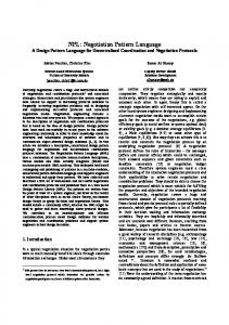
replace) informal approaches in order to allow users to know exactly when and how to use patterns. BPSL formally specify the structural as well as behavioral aspects of patterns at three levels of abstraction: pattern composition, patterns, and pattern instances [39]. BPSL is a very interesting approach. In BPSL the structural description of the pattern is described in first order logic, but the behavioral aspect of the design pattern is described in TLA (temporal Logic of Action). The most interesting point of the BPSL approach is the introduction of a very high abstraction layer in the description of the behaviors of Design patterns. David and Taibi introduced temporal relations (predicates) between instances, and the behavior is specified as temporal actions defined on those predicates [40]. The specification of the Observer Pattern according to BPSL whose class diagram can be seen in Figure 13 is shown in Figure 14.
Figure 13: Class Diagram of Observer Pattern [39]
51
Figure 14: BPSL Specification of Observer Pattern [39] The main idea of BPSL is derived from LePUS and DisCo, therefore it shares many of the advantages and disadvantages of these two languages. BPSL appears to be a very good approach for capturing the structural properties of the design pattern. Moreover, since the approach relies on a subset of First Order Logic, rather than the higher order logic of LePUS, the resulting specifications are generally less complex. This also means that as compared to LePUS, the expressivity of the language is reduced. It is unclear, however, whether the additional expressivity offered by LePUS is required to capture the
52
structural properties of interest. For the behavioral properties, the abilities and limitations of BPSL are identical to those of DisCo. One of the critic of these formally defined design patterns is that they have not been particularly clear on why the formal descriptions are needed and how the benefits of formally defined patterns can be utilized to outweigh the obvious costs of describing patterns using formal notations [41].
LANGUAGES BASED ON UML Since its emergence in the middle of nineteen nineties, the Unified Modeling Language (UML) has become de facto a standard for modeling object-oriented software systems [42]. UML is widely accepted by software community, and its bases are known by majority of software designers. UML is supported by almost all CASE tools for modeling object-oriented systems, such as for example Rational Rose, Enterprise Architect, Telelogic Tau, NoMagic MagicDraw, etc. UML based modeling techniques are still considered as semi-formal [9]. These languages also lack the support of pre and post conditions which sometime require textual support. Following two are good examples of UML based design pattern languages.
RBML Role Based Meta-modeling Language (RBML) proposed by Kim and Dae [3]. It is a meta-modeling technique to specify design patterns which is bases on UML. It is a language for characterizing families of UML models, and thus enabling specification of structure, interactions, and state-based behavior of a design pattern. The concept used in RBML is quite similar to the idea of Role-Elements of Pattern diagrams depicted by
53
Montes and Vela [43]. The concept of role-elements and bonds are not precisely defined in Role Element of Pattern diagram. However in RBML visual notations are based on UML1.4. Also for specifying the pattern properties Object constraint language (OCL) is employed [44]. Therefore RBML is more elaborative and addresses more aspects of solution proposed by a pattern [45]. In RBML specification of a design pattern defines a family of UML models in terms of model roles [3]. Each model role is associated with a UML meta-class as its base, and specifies properties that model element (which is an instance of the role‘s base metaclass) must possess to play the role. Design pattern specification is a set of model roles defining all restrictions required by the pattern. RBML proposes three mutually complementary perspectives for specification of a solution offered by a design pattern: 1. Static Pattern Specifications (SPS) – is set of model roles. The base UML meta-classes for SPS are Classifiers or Relationships. They define structural aspects of a design pattern. 2. Interaction Pattern Specifications (IPS) – is set of ‗interaction‘ roles. The base UML meta-class for IPS is Interaction, used to constrain interactions between pattern participants. An interaction role can consists of ‗lifeline‘ and ‗message‘ roles. The base UML meta-classes are Lifeline and Message respectively. Roles defined in IPS are associated with roles defined in SPS. 3. State Machine Pattern Specifications (SMPS) – is responsible for specifying state-based behavior of a design pattern. SMPS consist of set of ‗state‘, ‗transition‘ and ‗trigger‘ roles whose base UML meta-classes are State, Transition, and Trigger respectively.
The main drawback of Role Based Meta-modeling Language (RBML) is that it requires extension of UML meta-model with new elements. Meta-modeling is a first-class extension mechanism of UML2.0 handled through Meta-Object Facility (MOF) [42]. It
54
gives almost unlimited possibilities of extending UML2.0 meta-model. However up until today the UML modeling tools do not allow for modifications of the meta-model they work on. Moreover, notation for representation of a design pattern instance proposed in Role Base Meta-modeling Language is not clearly defined. However two approaches are suggested: 1. Notation mixing pattern specification with structure of classes from a design model – pattern specification and its instance are depicted in the same diagram and for each design model element taking part in the pattern instance it requires a dashed line linking it with corresponding role defined in the pattern specification. This solution clutters the presentation, especially when one design model element plays few roles in different design pattern instances [45]. 2. Approach basing on stereotypes – in this case for each model role defined in any design pattern a corresponding stereotype is created. Design model element playing a particular model role owns stereotype specific for this role, e.g. for model role called ‗Adapter‘ corresponding stereotype is created, class from design model playing model role ‗Adapter‘ owns stereotype . This approach has serious disadvantage, it requires new stereotype for each defined model role, and thus makes
the
number
of necessary
stereotypes
infinite
and
therefore
unmanageable. Moreover, such notation is ambiguous and confusing when model roles have the same names or when one design model element takes part in more than one pattern instance [45].
None of above mentioned approaches distinguishes particular instances of a design pattern.
DPML Maplesden et al. [4] proposed ―Design Pattern Modeling Language‖ (DPML) as a visual modeling language offering constructs (e.g. interface, operation) to specification of design patterns solutions and their instantiation. In this approach design pattern
55
specification is instantiated producing pattern instances. Design model elements are linked to corresponding participants of the pattern instances. Proposed mechanisms for specification of constraints are vague, and behavioral aspects of patterns are not taken into consideration. A pattern solution is realized by instantiating the specification, and binding the instantiated pattern elements to UML model elements. An instantiated diagram consists of ―proxy‖ elements that are instantiated from the pattern participants, and ―real‖ elements that are application-specific added during realization. A participant is played by more than one model element. This is specified by a notion called ―dimension‖. For example, Abstract Factory Design pattern from Gamma et al [1] is used by designers when they have to create variety of objects which are subclasses of a common root-class. DPML models Abstract factory design pattern with an interface named AbstractFactory and an operation named createOps. The createOps operation represents a set of operations so it has an associated dimension (Products) as there is one operation for creating each abstract product type. There is also a complete Declared_In relation running from createOps to AbstractFactory. This relation implies that all methods linked to the createOps operation in an instantiation of the pattern, must be declared in the object that is linked to the AbstractFactory interface. The Products interface has the Products dimension associated with it to imply there is the same number of abstract product interfaces as there are abstract createOps operations. A regular Return_Type relation runs from createOps to Products, implying that each of the createOps operations has exactly one of the Products as its return type.
56
These set of participants define just the abstract part of the Abstract Factory pattern. Another set of participants define the concrete part of the pattern which includes the factory implementations, the method implementations that these factories define, and the concrete products that the factories produce. The abstract part of the factory design pattern can be seen in Figure 15.
Figure 15: AbstractFactory design pattern in DPML [4] A prototype tool was developed for DPML. The tool can be used to build pattern specifications and UML class diagrams (what they call object diagrams), instantiate specifications and to check consistency between specifications and class diagrams. The pattern realization mechanism is similar to the templates in the UML in that pattern 57
participants are instantiated and bound to application elements. Such a template paradigm is limited in instantiation in that they only allow uniform instantiation. It is important to note that DPML can only be used to modal the generalized solutions proposed by design patterns, not complete design patterns [4].The DPML described is at a high level of abstraction and therefore will not contain the detailed information for accurately identifying design patterns in source code; it will only identify possible design patterns since the design pattern definition is course grained. Furthermore, it is not clear why a new notation had to be created instead of using the UML particularly when DPML is developed for UML models.
LANGUAGES BASED ON GENERAL PROGRAMMING LANGUAGES These are design pattern languages which are based on some general purpose programming languages. The prime examples for these types of design pattern languages are discussed below.
SPINE SPINE is loosely based on Prolog, as the HedgeHOg proof engine uses an internal proof system similar to Prolog‘s execution [46]. It also makes addition of patterns and variants easier to those who have programmed in Prolog before, rather than creating an entirely new syntax. Lastly, as the pattern definitions are declarative by nature, and as Prolog is a declarative language, the two closely match and thus is a natural choice for pattern definitions. Patterns are defined in terms of a number of standard predicates that correspond to the structural and semantic constraints. For example, structural predicates include
58
isAbstract(C) and typeOf(M). The arguments to these predicates are literals that identify the elements of the source code; for the same of simplicity, references to Java classes and methods
adopt
the
JavaDoc
notation
com.Example#method(type).
Thus,
isAbstract(‗com.Example‘) is true when com.Example is an abstract type. These can be joined with standard connectives, such as ―and‖, ―or‖, and implies to form logical statements over a range of classes and methods. As a result, it is possible to be very specific that a particular class has some combination of methods or field types. It‘s also possible to specify a constraint that exists over a range of classes as well. The two quantifiers ―forAll‖ and ―exists‖ can be used to iterate over set operators, such as methodsOf and subclassesOf (or even literal lists of classes). For example, and([isAbstract(C),forAll(subclassesOf(C),Cs. isFinal(Cs)]) declares that both C is an abstract class, and all of its subclasses (Cs) are final. At evaluation time, the forAll() is expanded into a conjunction([isFinal(Cs ), … ,isFinal(Csn)]) [46]. Together, these statements can be used to define certain properties of classes. This technique work for any statements about class implementation, though in the use so far this has just been used to reason about patterns. HEDGEHOG than reads pattern specifications from SPINE, which allows users to specify inter-class relationships and other path-insensitive semantic analysis (e.g., for Factory Method pattern, the predicate ―instantiates(M, T)‖ checks whether a method M creates and returns an instance of type T.), but other more complicated semantic analysis is hard-wired to its built-in predicates (e.g., ―lazyInstantiates(...)‖). Thus, SPINE is bounded by the capability of semantic analysis provided by HEDGEHOG [47].
59
The survey of the existing language has shown that most of the work in the formal design pattern languages is done in the verification and validation of the design patterns. As these languages are based on complex mathematical formalism therefore they cannot be integrated into different development environments. To create graphical output is also not the objective of these languages. The UML are based on graphical representation but they do not fully capture the behavioral aspect of design patterns. Furthermore they mostly require multiple diagrams to explain a design pattern, which makes them harder to decipher and more error prone. The comparison between features of the existing languages and our proposed language is shown in the Table 5 below: Table 5: Design Pattern Languages feature comparison
Basis
LePUS
eLePUS
mathematica l Logic
Mathematica l Logic
DPML UML based
Integra table in IDEs
No
No No (separa te IDE)
Platform Independ ence
N/A
N/A
Yes
Templat e Support
Yes
Yes
Yes
UML Support
learning curve For Programmers
No
Required Strong mathematical Background (High)
No
Required Strong mathematical Background (High)
Yes
UML knowledge required (Medium)
Yes
UML knowledge required (Medium)
Yes
Based on rigid Formal Apparatus (High)
No
Required Prolog understanding (Hard)
No
Knowledge for RDF & OWL Required (Hard)
RBML UML based DisCo
Temporal Logic of Action (TLA)
No
No
Yes
N/A
No
Yes
SPINE Prolog Ontology Based DPL
OWL (Web Ontology)
No
No
N/A
Yes
Yes
No
60
Graphic al Support
Target
Year
1999
No
Verification of Design Pattern on First Order logic basis
2001
No
Design pattern designing through mathematical formalism
UML
Creating Design patterns in UML
2002
2003
UML
Adding Support of Design Pattern in UML
1998
No
Capturing Behavioral Aspect of Design patterns
2006
No
Verification of Design Pattern Implementation in Application
2005
No
Creation of Knowledge Artifacts based on RDF
LOTOS
BPSL DPDL (Our Approach )
Temporal Logic of Action (TLA) Temporal Logic of Action (TLA)
XML
No
No Yes (using XML)
N/A
No
Yes
No
Yes
Yes
No
Based on rigid Formal Apparatus (High)
No
Based on rigid Formal Apparatus (High)
Yes
61
XML knoweldge required (Low)
2002
No
Verifying the Behavioral Aspect of Design Patterns
2002
No
Capturing Behavioral Aspect of Design patterns
Yes (Optiona l)
Easy initiation & implementation in Software Development
2010 *
CHAPTER 4 DESIGN PATTERNS
INTRODUCTION Design patterns are class combinations and accompanying algorithms that fulfill common design purpose. A design pattern expresses an idea rather than a fixed class combination. Accompanying algorithms express the pattern‘s basic operation [48]. As mentioned in Section 0, Gamma et al [1] have classified each of the design pattern in one of the three categories, depending upon the purpose and scope of the design pattern. These three categories are; (1) creational design patterns, (2) structural design patterns, (3) behavioral design patterns. A short description for these categories is given below.
Creational Design Patterns Creation design patterns help us to design applications involving collections of objects. They allow the creation of several possible collections from a single block of code, but with properties such as
Creating many versions of the collection at runtime.
Constraining the objects created, e.g. ensuing that there is only one instance of a specific class [48].
Structural Design Patterns Structural patterns address ways of combining classes via inheritance or class composition to form larger structures useful in design. Before application of the pattern, the functionality of the initial version of the system is typically carried out via a direct but
62
inflexible combination of objects. The new version introduces more objects and indirection, but provides a more adaptable and reusable architecture [49].
Behavioral Design Patterns Behavioral patterns are more complex than Structural patterns, as they concern algorithm definition and distribution between objects, and the patterns of communication between objects based on their data types [49]. We have selected three design patterns for detail discussion, from Gamma et al[1] list of design patterns. One design pattern from each category of; creational, structural and behavioral is selected. The same three design patterns are also used as examples in explaining Design Pattern Definition Language (DPDL) in Section 0 and Section 0.
ADAPTER Adapter design pattern is one of the most common structural design pattern [50]. Adapter design pattern adds extensibility in an application. Its common use in applications is also the reason for its selection for testing our approach of Design Pattern Definition Language (DPDL).
Intent To convert the interface of a class into another interface clients expect. Adapter design pattern lets incompatibly interfaced classes work together which in normal circumstances cannot work together [1].
63
Motivation Suppose a toolkit class that's designed for reuse isn't reusable only because its interface doesn't match the domain-specific interface an application requires. Consider for example a drawing editor that lets users draw and arrange graphical elements (lines, polygons, text, etc.) into pictures and diagrams. The drawing editor's key abstraction is the graphical object, which has an editable shape and can draw itself. The interface for graphical objects is defined by an abstract class called Shape. The editor defines a subclass of Shape for each kind of graphical object: a LineShape class for lines, a PolygonShape class for polygons, and so forth. Classes for elementary geometric shapes like LineShape and PolygonShape are rather easy to implement, because their drawing and editing capabilities are inherently limited. But a TextShape subclass that can display and edit text is considerably more difficult to implement, since even basic text editing involves complicated screen update and buffer management. Meanwhile, an off-the-shelf user interface toolkit might already provide a sophisticated TextView class for displaying and editing text. Ideally we would like to reuse TextView to implement TextShape, but the toolkit was not designed with Shape classes in mind. So we cannot use TextView and Shape objects interchangeably. How can existing and unrelated classes like TextView work in an application that expects classes with a different and incompatible interface? We could change the TextView class so that it conforms to the Shape interface, but that is not an option unless we have the toolkit's source code. Even if we do, it would not make sense to change TextView; the toolkit should not have to adopt domain-specific interfaces just to make one application work.
64
Instead, we could define TextShape so that it adapts the TextView interface to Shape's. We can do this in one of two ways: (1) by inheriting Shape's interface and TextView's implementation or (2) by composing a TextView instance within a TextShape and implementing TextShape in terms of TextView's interface. These two approaches correspond to the class and object versions of the Adapter pattern. We call TextShape an adapter [1].
Applicability Use the Adapter pattern when
User want to use an existing class, and its interface does not match the one you need.
User want to create a reusable class that cooperates with unrelated or unforeseen classes, that is, classes that do not necessarily have compatible interfaces.
User needs to use several existing subclasses, but it is impractical to adapt their interface by sub classing every one. An object adapter can adapt the interface of its parent class [1].
Structure A class adapter uses multiple inheritances to adapt one interface to another
Figure 16: Adapter Design Pattern [1]
65
Participants Target (Shape)
Defines the domain-specific interface that Client uses.
Client (DrawingEditor)
Collaborates with objects conforming to the Target interface.
Adaptee (TextView)
Defines an existing interface that needs adapting.
Adapter (TextShape)
Adapts the interface of Adaptee to the Target interface [1].
Collaborations Clients call operations on an Adapter instance. In turn, the adapter calls Adaptee operations that carry out the request [1].
Consequences Class and object adapters have different trade-offs.
A class adapter adapts Adaptee to Target by committing to a concrete Adapter class. As a consequence, a class adapter would not work when we want to adapt a class and all its subclasses.
Lets Adapter override some of Adaptee's behavior, since Adapter is a subclass of Adaptee.
Introduces only one object, and no additional pointer indirection is needed to get to the adaptee [1].
An object adapter
Lets a single Adapter work with many Adaptees—that is, the Adaptee itself and all of its subclasses (if any). The Adapter can also add functionality to all Adaptees at once.
66
Makes it harder to override Adaptee behavior. It will require sub classing Adaptee and making Adapter refer to the subclass rather than the Adaptee itself [1].
FACTORY METHOD Factory method belongs to the creational design patterns category of Gamma et al [1]. It is one of the heavily used design pattern in web application and especially in ASP.NET based web applications [51]. Due to its extensive use in web application, this design pattern is also used for testing our Design Pattern Definition Language approach.
Intent Define an interface for creating an object, but let subclasses decide which class to instantiate. Factory Method lets a class defer instantiation to subclasses [1].
Motivation Frameworks use abstract classes to define and maintain relationships between objects. A framework is often responsible for creating these objects as well. Consider a framework for applications that can present multiple documents to the user. Two key abstractions in this framework are the classes Application and Document. Both classes are abstract, and clients have to subclass them to realize their application-specific implementations. To create a drawing application, for example, we define the classes DrawingApplication and DrawingDocument. The Application class is responsible for managing Documents and will create them as required—when the user selects Open or New from a menu, for example. Because the particular Document subclass to instantiate is application-specific, the Application class can't predict the subclass of Document to instantiate—the Application class only knows
67
when a new document should be created, not what kind of Document to create. This creates a dilemma: The framework must instantiate classes, but it only knows about abstract classes, which it cannot instantiate. The Factory Method pattern offers a solution. It encapsulates the knowledge of which Document subclass to create and moves this knowledge out of the framework [1]. Application subclasses redefine an abstract CreateDocument operation on Application to return the appropriate Document subclass. Once an Application subclass is instantiated, it can then instantiate application-specific Documents without knowing their class. We call CreateDocument a factory method because it's responsible for "manufacturing" an object [1].
Applicability Use the Factory Method pattern when
A class cannot anticipate the class of objects it must create.
A class wants its subclasses to specify the objects it creates.
Classes delegate responsibility to one of several helper subclasses, and you want to localize the knowledge of which helper subclass is the delegate [1].
Structure
Figure 17: Factory Method Design Pattern [1]
68
Participants Product (Document)
Defines the interface of objects the factory method creates.
ConcreteProduct (MyDocument)
Implements the Product interface.
Creator (Application)
Declares the factory method, which returns an object of type Product.
Creator may also define a default implementation of the factory method that returns a default ConcreteProduct object.
May call the factory method to create a Product object [1].
ConcreteCreator (MyApplication)
Overrides the factory method to return an instance of a ConcreteProduct.
Collaborations Creator relies on its subclasses to define the factory method so that it returns an instance of the appropriate ConcreteProduct.
Consequences Factory methods eliminate the need to bind application-specific classes into your code. The code only deals with the Product interface; therefore it can work with any userdefined ConcreteProduct classes. A potential disadvantage of factory methods is that clients might have to subclass the Creator class just to create a particular ConcreteProduct object. Sub classing is fine when the client has to subclass the Creator class anyway, but otherwise the client now must deal with another point of evolution.
69
MEDIATOR Mediator design pattern belongs to the category of behavioral design pattern. Mediator design pattern is quite often use in simulations. If properly used, the mediator design pattern can provide an order of magnitude O(n) or more reduction in complexity and run time [52]. Due to these distinct capabilities of mediator design pattern we included it also in our testing of Design Pattern Definition Language (DPDL).
Intent Define an object that encapsulates how a set of objects interact. Mediator promotes loose coupling by keeping objects from referring to each other explicitly, and it lets you vary their interaction independently [1].
Motivation Object-oriented design encourages the distribution of behavior among objects. Such distribution can result in an object structure with many connections between objects; in the worst case, every object ends up knowing about every other. Though partitioning a system into many objects generally enhances reusability, proliferating interconnections tend to reduce it again. Lots of interconnections make it less likely that an object can work without the support of others—the system acts as though it were monolithic. Moreover, it can be difficult to change the system's behavior in any significant way, since behavior is distributed among many objects. As a result, you may be forced to define many subclasses to customize the system's behavior. As an example, consider the implementation of dialog boxes in a graphical user interface. A dialog box uses a window to present a collection of widgets such as buttons, menus,
70
and entry fields. Often there are dependencies between the widgets in the dialog. For example, a button gets disabled when a certain entry field is empty. Selecting an entry in a list of choices called a list box might change the contents of an entry field [1]. Conversely, typing text into the entry field might automatically select one or more corresponding entries in the list box. Once text appears in the entry field, other buttons may become enabled that let the user do something with the text, such as changing or deleting the thing to which it refers. Different dialog boxes will have different dependencies between widgets. So even though dialogs display the same kinds of widgets, they cannot simply reuse stock widget classes; they have to be customized to reflect dialog-specific dependencies. Customizing them individually by sub classing will be tedious, since many classes are involved. You can avoid these problems by encapsulating collective behavior in a separate mediator object. A mediator is responsible for controlling and coordinating the interactions of a group of objects. The mediator serves as an intermediary that keeps objects in the group from referring to each other explicitly. The objects only know the mediator, thereby reducing the number of interconnections [1]. For example, FontDialogDirector can be the mediator between the widgets in a dialog box. A FontDialogDirector object knows the widgets in a dialog and coordinates their interaction. It acts as a hub of communication for widgets:
Structure A typical Mediator design pattern will look like as in Figure 18.
71
Figure 18: Mediator Design Pattern [1]
Applicability Use the Mediator pattern when
A set of objects communicate in well-defined but complex ways. The resulting interdependencies are unstructured and difficult to understand.
Reusing an object is difficult because it refers to and communicates with many other objects.
A behavior that's distributed between several classes should be customizable without a lot of sub classing [1].
Participants Mediator (DialogDirector)
Defines an interface for communicating with Colleague objects.
ConcreteMediator (FontDialogDirector)
Implements cooperative behavior by coordinating Colleague objects.
Knows and maintains its colleagues.
Colleague classes (ListBox, EntryField)
Each Colleague class knows its Mediator object.
Each colleague communicates with its mediator whenever it would have otherwise communicated with another colleague [1].
72
Collaborations Colleagues send and receive requests from a Mediator object. The mediator implements the cooperative behavior by routing requests between the appropriate colleague(s) [1].
Consequences The Mediator pattern has the following benefits and drawbacks:
It limits sub classing. A mediator localizes behavior that otherwise would be distributed among several objects. Changing this behavior requires sub classing Mediator only; Colleague classes can be reused as is.
It decouples colleagues. A mediator promotes loose coupling between colleagues. You can vary and reuse Colleague and Mediator classes independently.
It simplifies object protocols. A mediator replaces many-to-many interactions with oneto-many interactions between the mediator and its colleagues. One-to-many relationships are easier to understand, maintain, and extend.
It abstracts how objects cooperate. Making mediation an independent concept and encapsulating it in an object lets you focus on how objects interact apart from their individual behavior. That can help clarify how objects interact in a system.
It centralizes control. The Mediator pattern trades complexity of interaction for complexity in the mediator. Because a mediator encapsulates protocols, it can become more complex than any individual colleague. This can make the mediator itself a monolith that's hard to maintain [1].
73
DESIGN PATTERN DEFINITION LANGUAGE (DPDL) As mentioned in literature review (Section 0) that most of the work done in the field of Design pattern definition language is in formal specification and mathematical area. The significance of this work cannot be denied but these formal specifications have more significance in the academia than in the industry. In software industry these formal specifications are not used much as they lack easy usage model, good tool support and also lack wide spread acceptance in the software industry. They also expects a strong mathematical background from the user [53]. Therefore we propose a solution for design pattern language which is based on XML. As this propose solution, Design Pattern Definition Language (DPDL), is based on XML therefore it can be used with large number of application, also XML is commonly accepted and used in the industry and can easily be integrated in tools [25].
OBJECTIVES OF DPDL Objective The main objective is to propose a language which helps the programmer and developers in the development and implementation of design patterns. Our primary objective is not a verification language for design patterns or creating new algorithms for design patterns.
DPDL Design Objectives DPDL has the following design objectives.
74
The Language should be Easy One of the most common complaint for the design pattern languages based on mathematical formalism is that they are not easy to understand by the programmers of the design patterns [53]. The syntax, rules and mathematical logic in these design pattern languages are not easy to grasp, that‘s why they are rarely used in the industry. Our target is to have a language which is easily understandable by the programmers and developers of the design pattern.
The Language should be Unambiguous As our target language is meant to be used for implementation, therefore one of the fundamental requirements is to be unambiguous. Any ambiguity in the language can result in a bug in the production code which will reduce the quality of the software produce. Therefore we need a language which is totally unambiguous and can be shared among development teams without any ambiguity.
The Language should be Extendible Another important objective for the language is the extendibility. As the technology and techniques for development are progressing so the design pattern language should be able to be extended with the future needs and requirement.
The Language should be based on existing technology Another important consideration put for the language is that it should be based on existing technology instead of creating something totally new. The benefit of this is that the existing technology will provide wider and faster acceptance to the language.
75
The Language should be able to produce graphical output. Although the language is based on text but it should be able to have graphical output. Graphical output provides quick overview for the design pattern, but some details are better express as text.
DPDL SCHEMA DPDL is based on XML. XML provides flexibility, simplicity and is quite common in the computing world [25]. With DPDL we tried to cover maximum possible characteristics of the design pattern in the simplest of the way, as one of our objectives is also to keep the language simple for the programmer and the end user. Therefore where textual input made more sense we used text. Where pre-defined values make more sense we used predefined values. Use of predefined values is critical as it helps the user to input correct values and put less stress on verification. For creating Design Pattern Definition Language, we started with analyzing the existing design pattern languages and their structural characteristics. We collected all the keywords and syntax used by textual based design pattern languages. We also analyzed the structural diagrams and behavioral diagrams of the design pattern created in UML based design pattern languages. From the sample of these design pattern languages we identified key concepts. Also elements, attributes and properties were grouped in appropriate categories. Then each item‘s use, in our proposed DPDL was evaluated. Also the UML diagrams were evaluated for the design patterns. Only class diagram and sequence diagram were used as they most appropriately represent the structural and behavioral characteristics of the design patterns. Then Schema was finally created with
76
the selected attributes. One design pattern from each behavioral, structural and creational category of Gamma et al [1] was selected (which were identified in Section 0), and written in DPDL. The behavioral and structural conformance of the DPDL of these design patterns was then verified and validated by creating class diagram and sequence diagram using our tool (mentioned in Chapter 0) and comparing them with class and sequence diagram created by commercial tools. Schema was then finalized by running multiple iterations of different object oriented design patterns. Figure 19 shows the high level schema for the proposed DPDL language. At the left most in the diagram is the DesignPattern element. It is important to note that for a different version of the same design pattern there will be different DesignPattern element. Each design pattern element has two main parts, its attributes and sub element. The attributes of design pattern cover different properties related to the design pattern but they do not describe the behavioral or structural aspect of the design pattern. Also the attributes can be mandatory or optional. Sub elements are used for describing the behavioral and structural aspect of the design pattern.
77
Figure 19: DPDL High Level Schema The design patterns have two basic aspects, the structural aspect and the behavioral aspect. In DPDL we covered them separately. Keeping them separate helps in number of ways. Firstly not in every case we need to both aspects of the design pattern. Some cases may only require structural aspect, so for them the design pattern in DPDL will have only the structural component. This helps keeping the schema clean and usable in all cases. Also by having both aspects totally separate provides easy way for creating enhancement for the future DPDL versions. So the extension covering only structural aspect will only be updating the structural component of the DPDL and similarly the enhancement for the
78
behavioral aspect will only make changes in the behavioral component without interfaring with the structural component. Also, a separate Element for Future enhancement is also left in DPDL. As the technology advances new ways and functionality will be created. So to cater to the future requirements we have placed a separate element where the extensions for the DPDL can be attached. The main element DesignPattern also have some attributes. Some of the attributes are for the DPDL like DesignVersion or AuthorName others are for Design Pattern. The details of the attributes of DesignPattern are discussed in the following section.
DESIGN PATTERN ATTRIBUTES Design Pattern attributes for the DPDL are as follows
Pattern Name (Mandatory) Pattern Name is the mandatory element of the DPDL DesignPattern attributes. The design pattern name is a handle which we use to describe a design problem, its solutions, and consequences in a word or two. Also naming a design pattern immediately increases our design pattern vocabulary. It makes it easier to think about designs and to communicate them and their trade-offs to others. Finding good names is an important task for design pattern developers.
Owner Name The owner name identifies the person, who originally introduced this design pattern.
79
Author Name The author name attribute indicates the name of the author who is designing this design pattern. He can be the head of the software team or the architecture designer or any researcher who is proposing a new design pattern.
Design Pattern Version With the passage of time many original design patterns have got different version providing more specialized capabilities. So a simple design pattern name is not enough in some cases. Therefore with the help of design pattern version we can more accurately identify the design pattern.
Intent Intent is a short statement that answers the following questions: What does the design pattern do? What is its rationale and intent? What particular design issue or problem does it address? Intent is a textual field.
Motivation Motivation is a scenario that illustrates a design problem and how the class and object structures in the pattern solve the problem. The scenario will help one understand more about the pattern that follows.
Applicability Applicability answers the question like what are the situations in which the design pattern can be applied? What are examples of poor designs that the pattern can address? How can you recognize these situations? It is also a textual field in DPDL.
80
KnownUses This field is added to provide some examples of this design pattern found in practical applications and real systems.
Related Patterns This field answers the questions like which design patterns are closely related to this one.
Consequences The consequences are the results and trade-offs of applying the design pattern. The consequences are critical for evaluating design alternatives and for understanding the costs and benefits of applying the pattern. The consequences for software often concern space and time trade-offs. They may address language and implementation issues as well. Since reuse is often a factor in object-oriented design, the consequences of a pattern include its impact on a system's flexibility, extensibility, or portability. Listing these consequences explicitly helps you understand and evaluate them.
Language If this design pattern is created for some application, then the language of the application can be mentioned in this attribute. The graphical output tool can also use this attribute to output correct diagram for the design pattern based on the language of the design pattern.
81
STRUCTURALATTRIBUTES
Figure 20: DPDL's Structural Attributes
82
Philosophy of Structural Attributes Model The structural properties of the design pattern are grouped in structural attributes element in DPDL, as shown in the Figure 20. It is important to mention that the schema was designed with the objective of handling both the particular instance of a design pattern and also the template of the design patterns. For designing the schema we looked into different design patterns mentioned in Gang of Four book [1]. An important observation is made that the design patterns are restricted to class level and they don‘t span across packages. As design patterns does not include package to package relationships. Secondly we also identified that each design patterns have some classes, functions, objects and relationship between classes. So we tried to separate them, as we feel that having separate elements for each of these aspects will help in future expansion and also provide and clean and tidy schema. It also helps to make very quick design pattern with just classes and relationship, and later on when one need to add more details they can be easily entered without changing the major structure of the design pattern.
SubGroup Element The purpose of subgroup inside each structural element of DPDL is to help in making a template of a design pattern. For example a single instance of a particular design pattern may have 2 children of a particular class and another instance of the same design pattern may contain 5 children of a particular class. Both design patterns are of the same type. So to verify these two different variations of the same design pattern we should have a single template for that design pattern, so that, all of the variations of the design pattern are handled in a clear and concise way. One way is that each possible instance of a design
83
pattern gets its own schema. This means that almost infinite schemas of the template will be created handling each instance which is not feasible at all. Also if in future some changes are made in a design pattern schema then these changes are required to be repeated in all the templates that were created for that design pattern. In our case we have introduced a SubGroup element in the four main elements (classes, operations, objects and relationships) of the structural attributes of DPDL. The attributes of subgourp elements are used for creating a very generic design pattern template which can cover many different scenarios. The detail description of the four elements in the structural attribute element is given in the following section.
Classes Element The classes element is a group of class element. All the participant classes of the design patterns are going to be mentioned in the classes element of the structural attributes. The subgroup element‘s attributes are mostly used for describing the template of a design pattern. A template designed in DPDL will able to handle all the possible instances of that particular design pattern. As the subgroup elements attributes are extending the group it contains (in the case of Classes Element subgroup is extending class elements), so for understanding the subgroup attributes we need to know class element’s attributes first. Therefore the description and explanation of subgroup element‘s attribute is given after the class element‘s attributes.
84
Class Element The class element is used in describing a class in a design pattern. All the details about the class of a design pattern will be mentioned in the class element. It has its sets of attributes that will help to describe the class.
Class Element Attributes The attributes of class are described below. The attributes are shown in Figure 21
Figure 21: Attributes of Class Element of DPDL
ClassName (Mandatory) ClassName is the most important attribute for the class element. It uniquely identifies the class in the design pattern. Each ClassName should be distinct in a particular design pattern.
85
ClassModifier (Optional) The attribute ClassModifier identifies if the class is private, public or protected. It can only have one of the predefined values, so that the user does not insert a wrong value for this attribute.
isDerived (Optional) This attributes is Yes for those classes which are derived from some other class. Otherwise the value of isDervived is no.
ParentId (Optional) If a class is a derived class then the class id of the parent class can be written in here. This attribute is more for the validation, otherwise in creating a graphical output or defining design pattern, it is not mandatory.
isAbstract (Optional) This attribute is Yes for abstract classes for other classes the value of isAbstract is no.
isVirtual (Optional) The attribute isVirtual is Yes for virtual classes for other classes the value of isVirtual is no.
isStatic (Optional) The classes which are static will have isStatic value as Yes and for other classes the value of isStatic is No.
isFinal (Optional) The classes which cannot be used as a base class for any other class are known as nonextendable class. Final is the keyword used for them in java and in C# ―sealed‖ keyword
86
is used for such classes. These classes are in DPDL represented by setting the attribute isFinal‘s value to Yes. Default value for isFinal is No.
isFriend (Optional) Friend classes are those classes which can access other classes methods and attributes without being related directly. These classes in our design pattern language (DPDL) are represented by having attribute isFriend set as Yes.
friendId (Optional) If a class is a friend class then the id of the friend class will be declared as this attributes value.
hasConstructor (Optional) If a class has one or more than one constructor then this value will be Yes, otherwise hasConstructor will have a value of No. The details about each constructor will be given in the Function element of the DPDL.
isParent (Optional) Those classes which are parent to some other class or base class for other classes will have this attribute value set to Yes. Other classes which are not parent will have the value as No
SubGroup Element Attributes The major use of subgroup element is in the template. Therefore its attributes are optional as the instance of design pattern can also be created in DPDL without using these attributes.
87
GroupId (Optional) The unique id of any group will be mentioned in this attribute. If one part of design pattern (a part can be a structural attribute like class, object, relationship and function) is dependent on another part of the design pattern then the group id of the independent part will be referenced in the dependent part. For example if there is one function against each class of a particular group, then the subgroup of the function, will refer the groupId of the class on which the function group is dependent. Class group will be independent in this example and its groupId will be used in the function subgroup.
noOfClasses; (Optional) This attribute defines how many instances of the class in this group have, which are exactly like the class defined in this subgroup through its attribute. This attribute can have numeric as well as textual value. So we can have values like 1, 2 or 5 etc, also a value like ―one-to-many‖ is acceptable, which can be used in defining templates. For example, suppose there is a class in the group, which is inherited from Shape class, then if we have value of noOfClasses as 3, then this means that there will be 3 classes in the design pattern, inherited from the Shape class. So in actual realization of the design pattern there will be three classes with all attributes of the class (see Section 0 for class element‘s attribute) identical to the attributes mentioned for the class in that group except for the className attribute which has to be unique in code. This way by defining the attributes of only one class in the DPDL and setting noOfClasse to 3, we can represent and then create three classes with same attributes.
88
Operations Element This part of the DPDL schema handles all the operations which are present in the design pattern. The sub-element of Operations is subGroupOp which is included for the purpose of handling template for design patterns. In the case of template of a design pattern, a function with same signature may be repeated in all classes of a particular group. Such situations can be handled by subGroupOp by describing just one operation in DPDL of the design pattern. Further detail about the subGroupOp attributes is given after the Function element, as subGroupOp attributes are extending the Function element‘s attributes. In case of defining a particular instance of a design pattern each function may be described in a separate subGroupOp or all the functions can be described in a single subGroupOp. All the functions are the child element of SubGroupOp which is the child element of Operation. Using this hierarchy helps in creating a very simple, extendible and easily understandable hierarchy for grouping all the operations. The Operations Element is the big container containing all the functions and operation of a particular design pattern inside it.
Function Element The actual function details are contained in this element. Figure 22 shows the attributes of function element graphically
89
Figure 22: Attributes of Function Element in DPDL
Function element attributes Following sub sections describe all the attributes of Function Element.
functionName (Mandatory) The name of the function, method, operation, property which this element is defining, is given in the functionName attribute. This function name can also be used in code. In remaining attributes of this section, the word function covers operation, method or property.
90
functionModifier (Mandatory) The modifier of the function is described in this attribute. Like classModifier the functionModifier also have pre-defined values from public, protect and private. This helps to avoid mistakes on the part of the designer and also helps with consistency.
containingClassId (Mandatory) The id of the class in which the function is contained is defined in this attribute. As we are focusing on object oriented design pattern, therefore all functions should belong to some specific class.
inputVariablesId (Optional) The variable name of all the variables which are the argument of the function are mentioned in this attribute in curly brackets ‗{}‘. A comma as a separator is used between two variable ids. In case there is no input argument to the function, then ‗null‘ without curly brackets is used.
inputVariablesType (Optional) The attribute inputVariableType stores the data type of the variable which are used as the argument of the function. They are also inside curly brackets ‗{}‘. A comma as a separator is used between two variable types. The first inputVariablesType belongs to the first inputVariablesId and so on. This also means that the number of inputVariablesType should be equal to the number of inputVariablesId. In case there is no input argument to the function, then ‗null‘ without curly brackets is used.
91
functionType(Optional) The attribute functionType tells what type of function it is. It is also a variable with predefined values of Method, Constructor, Destructor, Event, GetProperty and SetProperty. Default value is taken as method.
returnType (Mandatory) This property tells the return type of the function. The return type can be integer, string or other data type or it can also be void, if there is no return type.
isVirtual (Optional) If a function is a virtual function then this attribute is used to describe it. The value is Yes in the case of virtual function and No otherwise. Default value is No.
isAbstract (Optional) This attribute is Yes for abstract functions for other functions the value of isAbstract is no. The default value is No.
isFinal (Optional) If a function cannot be extended anymore then this property of isFinal is set to Yes. In other cases the value of isFinal is No. The default value is No.
isStatic (Optional) For static functions the value of isStatic is Yes. When the function is not static then the value is No. Default value is No.
92
isFriend (Optional) If a function can be accessed by other classes which are not the child class then the function is made as a friendly function. For such functions isFriend is set to Yes. Otherwise the value is No. Default value is No.
isOverRide If the function is an overridden on a base class function then this property of the function is set to yes, in other cases it is No. Default value is No.
SubGroupOp Element Attributes The major use of subgroupOp element is also in the template. Therefore its attributes are optional as the instance of design pattern can also be created in DPDL without using these attributes.
GroupId (Optional) The unique id of any group is mentioned in this attribute. With this unique group id this group can be referenced in any part of the DPDL.
noOfOperations (Optional) This attribute defines how many instance of similar operations are in the final instance of the design pattern. This attribute can have numeric as well as textual value. So we can have values like 1, 3 or 5 etc, also a value like ―one-to-many‖ is acceptable, which can be used in defining templates.
inGroupId (Optional) inGroupId is the group Id of another structural part of DPDL, which is referenced by this subgroup. It is used when number of operation in subgroup is dependent on another
93
group of DPDL‘s structural part, then this attribute is used to identify the independent group. The inGroupId always come when forEach or inEach attribute is used. Its use is explained in Section 0 and Section 0.
forEach (Optional) The value of this attribute can be class, object, operation, function. To understand the use of forEach, take an example of a design pattern template in which there is a separate set function for all the classes of a particular subgroup, child of classes element, in some class (say classA),. Now as we discussed in Section 0, that the template should handle all variation of design pattern, so different variation of the same design pattern can have different number of classes. So in template we have to say that for each class in subGroup x(where x is id group of independent subGroup), there should be a function in classA, with same input and return types for all classes of subGroup x. forEach attribute identifies for which structural part this function is repeated for. In our case it is class for which it is repeated for. Now the inGroupId identifies the id of the group (like subGroup x) whose number of classes it will be based on. When forEach is used in the subGroupOp then only the operationName is changed. The numbers of identical function which are created are equal to the number of classes in the subgroup identified in inGroupId and all these functions have same containing class. It is also explained through figure in Figure 23.
94
ParentClass
Explicitly Defined
Implicitly Defined Child Classes
OtherClass ChildN
ChildA +setChildA(in a : int) +() +setChildN(in a : int)
* * * *
Explicitly Defined
Implicitly Defined
Figure 23: Example of forEach in Function.
inEach (Optional) This variable is also used in conjunction with the groupId attribute. Whenever inEach is used in any type of subgroup, then there should be an inGroupId attribute present. inEach attribute is added to handle the situation when user wants to describe that a particular function is present in all the classes in a subgroup, and the value noOfClasses of that subgroup is more than 1. There can be two cases, one scenario is that we have some numeric value (e.g. 2), in noOfClasses of subGroup element. In this case we can either show two functions, one for each class, in the DPDL, or we can show it in the DPDL by just showing one function and have the value of inEach attribute as class and give the id of subGroup to inGroupId. This way it tells the programmer that exact function which is defined in subGroupOp is present in each class of a particular subgroup 95
whose value is given in inGroupId. The value of the attribute inEach is class as it is referring to a subgroup which is child of classes element. Second case is when we are defining a design pattern and the value of noOfClasses of subGroup element of classes, is ―one-to-many‖. In this case we don‘t know the exact number of classes. So we require a way to mention that this function is dependent on a particular subGroup of Classes element, and each class of that subGroup needs to have this function. The id of that subgroup is refers in inGroupId attribute. It is shown in Figure 24.
ParentClass
Explicitly Defined
Implicitly Defined Child Classes
ChildA
ChildN
+drawShape()
+drawShape()
Explicitly Defined
Implicitly Defined
Figure 24: Example of inEach for Function
96
Objects Element This element acts as a container for all the objects of the design pattern. The sub element of Object is SubGroupOb. SubGroupOb has the same purpose of providing support for the template design patterns by describing multiple objects through defining only one object of that type in the DPDL. The attributes of the SubGroupOb and their description is given after the Object Element.
Object Element A single object is defined by the Object Element. All the attributes of a particular object are described in the object element.
Figure 25: Attributes of Object Element in DPDL
Object Element Attribute Following are the attribute which an object or a variable can have in DPDL.
objectName (Mandatory) The objectName is the unique identifier for the object or the variable. An object can have same name if they are in two different classes
97
containingClass (Mandatory) The containingClass attribute tells in which class the object is present.
objectClass (Mandatory) The objectClass tells from which class the object belongs.
objectModifier (Optional) The objectModifier like functionModifier tells the previlage level of the object. It also has predefined values of private, public or protected. Default value is private.
isList (Optional) If the object is a list or an array then this attribute of the object is set to Yes, otherwise it is set to No. Default value is No.
ListType (Optional) If the isList attribute is Yes, then ListType can be set to some array type like array, hash table or link list.
SubGroupOb Element Attributes The major use of subgroupOb element is also in the template. Therefore its attributes are optional as the instance of design pattern can also be created in DPDL without using these attributes.
GroupId (Optional) The unique id of any group will be mentioned in this attribute. With this unique group id this group can be referenced in any part of the DPDL and dependency between one part of the DPDL to another part can be created.
98
noOfObjects (Optional) This attribute defines how many identical objects are there like the ones mentioned in this group. This attribute can have numeric as well as textual value. So we can have values like 1, 3 or 5 etc, also a value like ―one-to-many‖ is acceptable, which can be used in defining templates.
inGroupId (Optional) inGroupId is the group Id which is referenced by the subgroupOb. It is used when number of objects or fields in subgroup is dependent on another group of DPDL‘s structural part. The value of this attribute is id of another subgroup. The inGroupId always present when forEach or inEach attribute is used. Its use is explained in Section 0 and Section 0.
forEach (Optional) The value of this attribute can be class, object, operation, function. To understand the use of forEach, we need to take an example of a design pattern template, in which there is a class (e.g. class y) which has an object of all the classes of some other subgroup (e.g. subGroup x). Now as we discussed in Section 0, that the template should handle all variation of design pattern, so different variation of the same design pattern can have different number of objects in the class y depending upon the number of Classes in subGroup x. So in template we have to say that for each class in subGroup x, there should be an object of it in class y. The attribute forEach identifies for which structural part this object is depended on. In our case it is class subgroup on which it is dependent. Now the inGroupId will identify the id of the group (subGroup x) whose number of classes it will be based on.
99
When forEach is used in the subGroupOp then only the objecClass id is changed. The numbers of objects created are equal to the number of classes in the subgroup identified in inGroupId and all these objects have same containing class.
inEach (Optional) This variable is also used in conjunction with the groupId attribute. Whenever inEach is used in any type of subgroup, then there should be inGroupId attribute present. inEach attribute is added to handle the situation when user wants to describe that a particular object or field is present in all the classes in a subgroup (subGroup o), and the value noOfClasses of that subGroup o is more than 1. subGroup o is the child of the classes element. There can be two cases, one scenario is that we have some numeric value (e.g. 2), in noOfClasses of subGroup o. In this case we can either show two objects, one for each class, in the DPDL, or we can show it in the DPDL by just showing one object and have the value of inEach attribute as class and give the id of subGroup o on which it is dependent on, in inGroupId. This way it tells the programmer that exact object which is defined in subGroupOb is present in each class of a subGroup o. The value of the attribute inEach will be class as it is based on a subgroup of classes. The value of inGroupId is subGroup o Second case is when we are defining a design pattern and the value of noOfClasses of subGroup o, is ―one-to-many‖. In this case we don‘t know the exact number of classes. So we require a way to mention that this object is dependent on a particular subGroup which is subGroup o, and each class of subGroup o has the object described in this sub group.
100
Relationship Element One last piece of important information for any class diagram structure and especially for the design pattern structure is the relationship between classes. The relationship tells how the classes are going to interact with each other. Many design patterns differ only on the basis of relationship between the classes. Relationship element also contains SubgroupR element whose child is Relation which contains relationship information between two classes. The SubgroupR element is extending the capability of Relation element to handle templates therefore the SubgroupR element and its attributes are described after the Relation Element.
Relation Element The relation element is the element in the schema in which each individual unique relationship between two classes is described. The attributes of the relation element are related to describing each relationship accurately and completely. They are kept simple and easy to describe. Below in Figure 26 the relation element is shown graphically.
Figure 26: Attributes of Relation Element in DPDDL
101
Relation Element Attributes relationId (Optional) The attribute relationId is for identifying the relation between two classes uniquely. Identification of the relation is the sole purpose of it.
RelationName (Mandatory) The relationName attributes identifies the name of the relationship. This attribute also have predefined values from Association, Generalization, Aggregation, Composition, Dependency, Realization and Nesting. In future more relationship types can also be added.
initiatingClass (Mandatory) Each relation is between two classes exactly. The initiating class is the class starting the relationship or is invoking a relation.
endClass (Mandatory) The class which is invoked is identified in endClass. The id of the class which is on the receiving end is given in endClass attribute.
SubGroupR Element Attributes The major use of subgroupR element is also in the template. Therefore its attributes are optional as the instance of design pattern can also be created in DPDL without using these attributes.
102
groupId (Optional) The unique id of any group is mentioned in this attribute. With this unique group id this group can be referenced in any part of the DPDL and dependency between one part to another part can be created.
noOfRelations (Optional) This attribute define how many identical relations are in the design pattern like the ones mentioned in this group. This attribute can have numeric as well as textual value. So we can have values like 1, 3 or 5 etc, also a value like ―one-to-many‖ is acceptable, which can be used in defining templates.
inGroupId (Optional) inGroupId is the group Id which is referenced by the subgroupR. It is used when the number of relationship in subgroup is dependent on another group of DPDL‘s structural part, then the value (id of another subgroup) in this attribute will be used to identify the independent group. The inGroupId always come when forEach is used. Its use is explained in Section 0.
forEach (Optional) The value of this attribute can be class, object, operation, function, but in subGroupR its almost always class. To understand the use of forEach, we need to take an example of a design pattern template, in which there is a parent class which can have many child classes. The child classes belong to different subgroup (e.g. subgroup R). Now as we discussed in Section 0, that the template should handle all variations of design pattern, so different variations of the same design pattern can have different number of child classes in subgroup R. So in template we have to show that the relation between parent and all 103
child classes is a generalization relationship. The inGroupId will identify the id of the child classes subgroup which is subgroup R in our case. The numbers of relationships in the realization of the pattern is equal to the number of child classes based on subgroup R’s noOfClasses value.
changingClass This attribute should always be used with forEach attribute. It is used when with one relationship information we want to give information about large number of identical relationship. So we have a value in inGroupId, identifying which class is changing, but we also need to identify which end this class belongs in the relationship i.e. is it initiating class or the end class. So this attribute has the value of either initiating class or the end class..
BEHAVIORALATTIBUTES Behavioral Attributes of a design pattern are contained in the behavioralAttribute element. Behavioral attribute covers how the classes are interacting and how they invoke each other and achieve the desired objective of the design pattern. As the first target, the unique behavioral function of design patterns were identified, then we tried to create a recursive solution in XML which can allow any combination of behavioral aspect to be described in DPDL. Another important aspect which we have to remember in the behavioral attributes is that the sequence is very important. For structural attributes of a design pattern, the sequence of writing different objects or functions or relationships do not matter as in the end the
104
result will be the same. But in behavioral elements the sequence is important to inform the correct behavior.
Overview of BehavioralAttributes Element BehavioralAttribute element in our schema contains five element. These elements are SetObject, call, create, loop and condition. Each of the element can call the other behavioral aspect inside it. This gives the flexibility to have any sort of combination to describe the design pattern. It is also a good flexibility for specifying future design patterns as it does not pose any limitation on the design patterns. BehavioralAttribute is just a big container which is keeping all the behavioral elements in it. The behavioralAttribute element in itself does not have any attribute, it has other for other element which are describing the behavioral aspect of the design pattern. Graphically the structure is represented in Figure 27
Figure 27: DPDL's Behavioral Attributes
105
There are three special common attributes in each BehavioralAttribute Elements for handling the templates. These attributes are forEach, inEach and inGroupId. These attributes are optional and will not be discussed in each Element of the BehavioralAttributes separately. These attributes are explained after all the Behavioral attribute‘s elements at the end in Section 0.
SetObject Element SetOject attribute is for assigning a variable or object with some other object. In developer‘s term it represents typecasting of one object into another object or object type. Typecasting is quite commonly used in different design patterns.
SetObject Element’s Attributes Following are the attributes of SetObject Element. The attributes are shown in schematic diagram in Figure 28
Figure 28: SetObect Element's Attributes in DPDL
106
CallingClass (Mandatory) The class that contains this behavior of typecasting of object to some other object is identified in the callingClass attribute.
ObjectClass (Mandatory) The attribute ObjectClass describe the current class of the object to which it belongs.
ObjectId (Mandatory) The attribute ObjectId is the unique identifier of the object.
SetTo (Mandatory) The SetTo attribute identifies the new Type to which the object is set.
SetType (Optional) The SetType attribute identifies if the object is being changed through an object or through a class. So its value can either be object or class.
Call Element Call is the most widely used behavioral element. Whenever a function is invoked in a design pattern, call element is used to capture it. The attributes of Call elements are as follow:
107
Figure 29: Call Element's Attributes in DPDL
Call Element’s Attributes CallFrom (Mandatory) The CallFrom attribute identifies from which class the call is invoked. So the calling class id is given as the value of CallFrom
CalledFunction (Optional) The CalledFunction is the attribute which stores the name of the function which is being called.
108
CallerFunction (Optional) If the call to the function is made from inside another function, then the name of the function from which the CalledFunction is invoked is stored in CallerFunction attribute
CalledClass (Mandatory) The CalledClass attribute identifies the class of the CalledFunctions. The value of the called class is saved in the CalledClass attribute.
CalledThrough (Optional) Each function can be called through either directly or through some object. If the function is not called through any object then the value of the CalledThrough is null, otherwise the name of the object is given, through which the function is called, in this attribute.
CallingClass (Mandatory) The class from which the function is called is identified in this attribute.
VariablesPassed (Mandatory) Some functions require some input variables also. The variable name for these functions is passed through this VariablePassed attribute.
VariabledTypes (Mandatory) If the invoked function has input variables then the type of those variables is identified in this attribute.
Returns (Mandatory) The returns attribute identifies the object type which is returned by the invoked function.
109
Create Element The create element is the third behavioral element. This element is used for depicting the creation of some object in the design pattern. The attribute of create element identifies the creation properties.
Create Element’s Attribute The attribute in the create elements are listed below with the description. The graphical schematic representation is shown in the Figure 30
Figure 30: Create Element's Attributes in DPDL
110
ObjectId (Mandatory) The attribute objectId identifies the object. Whenever a new object or variable is declared it is given a unique identifier.
createType (Mandatory) This attribute identifies if the createType is new.
Collection (Mandatory) If the object which is being created is some sort of array then the collection attribute will have the value as Yes otherwise it has the value as No.
CallingClass (Mandatory) The class in which the object is created is identified in CallingClass attribute of the Create Element.
ObjectClass (Mandatory) The class of the object which is being created is identified in the ObjectClass attribute.
Returns (Mandatory) Sometime the object returned by called class is not the object of the called class but it is an object of the some other class. In that case the returns will be different then objectClass
Variables (Optional) For creating an object, sometime variables are also required to be passed. The name of these variables will be given in the Variables attribute.
variableTypes (Optional) The type of the variables which are passed is given in the variableTypes 111
Loop Element Loop is another important behavioral element for the DPDL. All the loop which are the part of the design pattern are described through loop element. The loop element has following attributes
Figure 31: Loop Element's Attributes in DPDL
Loop Element’s Attributes Class (Mandatory) This attribute contains the name of the class in which this loop is present.
Function (Mandatory) If the loop is inside the function then the name of the function is given in the Function.
ExitCondition (Optional) This attribute contains the condition on which the loop will terminate.
112
numberOfIterations (Optional) If the number of iteration is fixed then this attribute can have a numerical value.
Condition Element Behavior of design pattern is not always sequential. In those cases on the basis of some condition the sequence of the program is interrupted which is represented by conditional statement in programming language. For this we have condition element in our DPDL
Condition Element’s Attributes The attributes for condition elements are shown in the below Figure 32
Figure 32: Condition Element's Attributes in DPDL
ConditionType (Mandatory) The condition structure in most cases has two branches. Sometime they are called as normal code path and alternate code path. The conditionType tells which of the code path this condition is representing. The conditionType can be extended to more than 2 options.
113
It should also be mentioned that the correct representation of ConditionType is in the hands of the end user. For example if a alternate code path is represented without first mentioning the normal code path then the language DPDL will consider it correct, where as in normal environment this will be considered as a bug. The reason for not handling is that XML does not provide very fine grained control to handle such a condition. Moreover the benefit is that this allows easy extendibility for handling more than two code paths. Switch condition can also be supported by ConditionType.
CallingClass (Mandatory) The name of the class in which this condition is present is mentioned in the callingClass attribute
FunctionName (Mandatory) The name of the function in which the condition is used is mentioned in the functionName attribute
conditionText (Mandatory) The statement or text of the condition is mentioned in conditionText attribute.
Common Attributes inGroupId (Optional) inGroupId is the group Id of another structural part of DPDL, which is referenced by any behavioral element. It is used when an action (behavioral element like call or created) is dependent on another structural part, then this attribute is used to identify the independent group. The inGroupId always come when forEach or inEach attribute is used. Its use with forEach n inEach is explained in Section 0 and Section 0 respectively.
114
forEach (Optional) The value of this attribute can be class, object, operation, function. To understand the use of forEach, take an example of a design pattern template in which there is a create call for all the classes in a particular subgroup (e.g. subGroup x). Now as we discussed in Section 0, that the template should handle all variation of design pattern, so different variation of the same design pattern can have different number of classes. So in template we have to say that for each class in subGroup x(where x is id group of independent subGroup), there should be a create call in classA. forEach attribute identifies for which structural part this create call is repeated for. In our case it is class for which it is repeated for. Now the inGroupId identifies the id of the group (which is subGroup x) whose number of classes will determine the number of create calls.
inEach (Optional) This variable is also used in conjunction with the groupId attribute. Whenever inEach is used in any type of subgroup, then there should be an inGroupId attribute present. inEach attribute is added to handle the situation when user wants to describe that a particular behavioral action (e.g. call) is present in all the classes of a subgroup (e.g. subGroup x). The value noOfClasses of subGroup x should be more than 1. In this case we can show it in the DPDL by just showing one call element with all the attributes and have the value of inEach attribute as class and give the id of subgroup x to inGroupId in the call element. This way we are showing that exact call is present in each class of a subGroup x. The value of the attribute inEach is class as it is referring to a subgroup which is child of classes element.
115
116
CHAPTER 6 TOOLS As mentioned earlier also that DPDL is based on XML. The XML itself can be written in any editor. The schema for the DPDL has been created in Altova XMLSpy 2010 version [54]. The target for DPDL is to provide complete information for the development and implementation of a design pattern. Design pattern have structural and behavioral properties and the Design Pattern Definition Language (DPDL) also covers them separately. So to verify and validate that the language we have developed (DPDL) is complete, comprehensive and accurate for implementing a design pattern we developed tools to generate graphical output from DPDL and compare it to the target output. This graphical output is UML diagrams. The graphical output gives us two benefits. The first benefit of the graphical output is that the UML diagrams are generated. UML is one of the most widely used standards in the software industry. So by creating a graphical output which is in fact a UML diagram, we are getting conformance for our proposed Design Pattern Definition Language (DPDL). Secondly, currently there are many tools available which can generate a source code from the UML class diagram. So if an accurate class diagram can be generated from a DPDL version of a design pattern then this means that DPDL can be used for the implementation of the design pattern. This fulfills our main objective for DPDL. Two tools have been created for DPDL. The first tool is for the creation of a class diagram. The class diagram is exactly as the UML class diagram. Only the structural attributes of the DPDL have been used for the creation of the class diagram. This also
117
shows that DPDL is simple and comprehensive at the same time. If the requirement is to have only the structural aspect of the design pattern than one does not need to specify the behavioral attributes. Similarly even in the structural aspect if only the abstract information is required then only Classes and Relationships element of the Structural Attributes can fulfill the requirement, without needing to give the details about the objects and operation elements. The second tool which is created is for the validation of the behavioral aspect of the DPDL schema. UML have a few diagrams for identifying the behavioral aspect of the design pattern and the most widely used and the most comprehensive is the sequence diagram. The Behavioral attributes of the design pattern are used to create a sequence diagram. Here it is also worth mentioning that not all the attributes and properties in the behavioral element of the DPDL are used for creating a sequence diagram. So there is more information with which other or more comprehensive diagrams can be created. Moreover these attributes are used to cover all the aspects of the design pattern implementation with detail and completeness.
DPDL CLASS TOOL The DPDL class tool is built in C#. It is based on an open source NClass tool which is under the GPL license [55]. The tool is for basic stuff and its primary objective is to see if the class diagram can be generated from the DPDL of a design pattern. The layout of the DPDL Class Tool is displayed in Figure 33.
118
Figure 33: DPDL Class Tool The layout of the program is pretty simple. It has a top menu bar, quick action buttons bar and then on the right side there are two windows. One is text for design pattern name. More information can be added in this box. The second area is a zoom out graphical representation.
DPDL Class Tool Features The drop down menu consists of a File button. Other than file button there are Edit, View, Plug Ins and Help buttons. Each button has further options. The File button contains New, Open, Save, Save As and Exit functions. The View Button contains
119
normal operations like Cut, Copy, Paste, Delete and Select All. The Plug Ins button is for the other developer to add more functionality into it. The View Button has options related to the View of the Program. Both Side windows can be closed for a full screen view of the diagram. If one, side window, is closed then it will take the whole of the right side window space. Also the view button has zoom options, auto zoom. It also contains the Options button in which different options can be set. Finally the Help button contains Check for updates button, which is used for future updating of the software. Also it has About DPDL Class button.
Figure 34: DPDL Class Tool View Menu Most of the current commercial tools for creating class diagrams have two portions of xml in their output. One portion of the saved file (save file can be in xml or in any other proprietary format) is dedicated to the design aspect of the class diagram. So it has all the data to reproduce the diagram at the exact same location with the exact same information. This component has attributes like line, square, text and so on. Then these attributes have
120
starting locations in pixels like (x, y). This information is used for the exact placement of the class diagram objects when it is reopened. The second component in these class diagrams is about the class objects in the class diagram. Our tool is using only the class objects to generate the class diagram. This is the first tool which is not using any point coordinates for generating the class diagram. This shows that the class information is comprehensive enough to generate the whole class diagram of the design pattern based on the information stored in the DPDL.
Creating Class Diagram from DPDL Class Tool
Figure 35: File Menu Options To open a design pattern DPDL, we need to click on File Open, this opens a dialog box through which a dpl file of the design pattern based on DPDL schema can be opened. Figure 36 shows the file open dialog. When the file is selected and clicked to be opened,
121
the tool parses the file and if there is no error it opens the class diagram of the design pattern.
Figure 36: DPDL Class Tool Open DialogBox On the right side window the user can see the design pattern name which is taken from the design pattern file. The view of the class diagram is shown in Figure 37.
122
Figure 37: Class Diagram in DPDL Class Tool
Other Options in DPDL Class Tool One of the important features added in the tool for the DPDL is the generation of source code from the class diagram that had been generated from the source code in the first place. After the diagram has been generated from the file the Diagram menu has an option to generate source Code. On clicking this option the source code is generated for the design pattern. But we have to remember here that the source generated is based on the class diagram, which itself is based on part of the input file. This option can be seen in the Figure 38 displayed below.
123
Figure 38: Option for generating Source Code in DPDL Class Tool There is another option of making changes in the class diagram inside the tool. The class diagram provides all sets of options which are used in Class Diagram creation. These options include adding new classes in the diagram, adding new methods and variables in the diagram. Also they include the relationship options between two classes which can exist.
Current Limitation of DPDL Class Tool There are a few limitations in our current tool. One of the limitations is that we have created the design pattern keeping in view the C# language, therefore the tool currently handles design patterns for the C# language. The difference is of certain keywords which are valid in C# and invalid in Java and vice versa, but this is not a very big limitation and can easily be rectified in the future version of the tool.
124
The second limitation is that the tool is generating the source code for the C# currently. This feature is also more for the proof of concept. As the tool can generate the C# source code from the class diagram which is in turn created from the design pattern in our DPDL, therefore it shows that the language itself is robust enough to use for the implementation of the design pattern. In future better and more feature-rich tools can be created for it to generate source code in other languages for the design pattern. Another very important limitation in the current tool is that it can make changes in the class diagram but these changes cannot be saved in DPDL compliant xml. As mentioned earlier that all tools currently in market save the class diagram with the diagram component which is used to build the class diagram. So the default behavior of the tool is to save the diagram components of the class diagram created in the tool. Whereas the DPDL does not have any diagram component and it saves information relevant to the implementation of the design pattern. So in current state the tool is missing the feature of storing the DPDL compliant xml.
DPDL QTOOL As the design pattern has a behavioral aspect which is in some cases as important as the structural aspect. So to check the behavioral attributes we decided to create a tool for generating sequence diagrams from the behavioral attributes in DPDL. This tool is also built from NSequence which is based on a text input and is available online under LGPL [56]. The tool has been modified to take the DPDL xml as an input and generate a sequence diagram from it.
125
Figure 39: QTool, the Sequence Diagram Generator Overall sequence diagram tools are very rare. Secondly all current sequence diagram tools generate either image file as an output, or they generate the diagram component only. The diagram components describe the sequence diagram from the perspective of a diagram making our tool, the first tool to use some sort of XML to generate a sequence diagram. This makes an interesting case also for how to represent the sequence diagram through the xml only and also if it is possible to have an xml for the sequence only.
DPDL QTool Feature The sequence diagram tool is quite simple and it focuses only on the creation of the sequence diagram from the DPDL xml. There are only three items in the menu options in DPDL QTool. The first is the File menu option. This option includes Open, Close, Exit and Export. Export option is the option through which the user can export the sequence diagram as any graphic image. Currently the user can export it as a PNG file.
126
Figure 40: File Menu options in QTool The Open option is the option through which the user can open a DPDL xml file. The application parses through the program and then the sequence diagram is generated. If there is some error the application quits. The second menu option is Edit. This menu option has Cut, copy, paste and preference options. The cut, copy, paste is not currently useful in the sequence diagram but the Preference option contains the options to change the color and font for the sequence diagram
127
Figure 41: Edit Option in QTool The last option on menu bar is Help. This option contains Index, content and About options. The index and content is used for giving information about using the application and the About option opens a dialog giving the minimal details about the program.
Creating Sequence Diagram in QTool Creating a sequence diagram from the DPDL file in QTool is pretty simple. The user needs to select Open from File menu option and a file open dialog box will appear. The user needs to select a valid DPDL file which has a behavioral component also. The application then parse through the DPDL file and display the sequence diagram in the window.
128
Figure 42: QTool Open DialogBox
The QTool contains only 1 display window. All the information of the sequence diagram and sequence diagram itself is displayed in that window.
Current Limitation of QTool The QTool itself is a first attempt of generating a sequence diagram from any xml. Therefore this effort is opening a new front towards representing the sequence diagram. It also means that this effort has few limitations. The first limitation is that the tool is not saving the output in the DPDL compliant xml. The second limitation is that the tool does not provide any editing options. As this is the first tool designed for the creation of the sequence diagram, therefore further study is required to see which type of editing options can be provided in sequence diagrams. Also how these options can be implemented in the tool.
129
130
CHAPTER 7 VERIFICATION & VALIDATION This section deals with the evaluation of the proposed design pattern definition language. Verification and validation is the process of checking that a product, service, or system meets the specifications and that it fulfills its intended purpose. It is sometimes said that validation can be expressed by the query "Are you building the right thing?" and verification by "Are you building it right?" "Building the right thing" refers back to the user's needs, while "building it right" checks that the specifications be correctly implemented by the system [57]. As the proposed design pattern definition language is not a software or application, therefore the validation & verification process does not include test activities like unit testing, integration testing etc. The formal approaches for validation & verifications require great understanding of the techniques involved and are also quite complex and extensive, which is beyond the scope of this thesis. In DPDL verification & Validation, we try to cover the topics of correctness & completeness. We start by taking examples.
DESIGN PATTERN INSTANCES Adapter Design Pattern The adapter design pattern (often referred to as the wrapper pattern or simply a wrapper) translates one interface for a class into a compatible interface. An adapter allows classes to work together that normally could not because of incompatible interfaces, by providing
131
its interface to clients while using the original interface. The adapter translates calls to its interface into calls to the original interface, and the amount of code necessary to do this is typically small. The adapter is also responsible for transforming data into appropriate forms. For instance, if multiple Boolean values are stored as a single integer but your consumer requires a 'true'/'false', the adapter would be responsible for extracting the appropriate values from the integer value. We will first present DPDL of the adapter design pattern. Here it is important to mention again that the schema of DPDL is made in Altova XMLSpy and also the design patterns are created in Altova XMLSpy [54]. But any XML editor can be used. Figure 43 shows the example of Adapter design pattern in DPDL. We can see that the whole design pattern has three major portions. First is the Structural attributes. Second is the Behavioral and the last one is for the future.
132
Figure 43: DPDL of Adapter Design Pattern The first section which is structural attributes contains four parts. We start with the first part which is the Class part. The adapter design pattern has at least three classes. One is the target with which the client class or classes interact. The target class then hands over the request to the adapter class. Adapter class is interacting with a number of Adaptee classes. So the adapter class selects one of the specific classes based on some criteria for the specific request. Also the adapter class is derived from the Target class. But the Target class is not an abstract class; the function in it is a virtual function, which we will discuss in the Operations section.
Structural Description in DPDL The Classes part of the Structural attributes is handling all the classes‘ information. In this example we have added all the classes under a separate sub group, but we can add
133
them in the same sub group, because all of them have one instance of them in the design pattern. As this is a specific instance of adapter design pattern.
Figure 44: Class in DPDL for Adapter Design Pattern The Classes part of the DPDL also has a client class in it. This is determined by the user if there is a need to add the client class or not. It can show how to interact with the design pattern. There are four classes including the client class in the above used instance of Adapter design pattern. The client accesses the functionality of the Adaptee class through the Target. Target class is the parent of the Adapter class which is invoking the functionality of the Adaptee.
134
Figure 45: Operations in DPDL for Adapter Design Pattern The second part of the Structural attributes is Operations. All operations which are done in the design patterns are important for the design pattern, are mentioned in this part of the DPDL. The instance of adapter design pattern which we have taken for example has three operations. The first one is the Request operation which is in Target Class and is of type virtual. The second one is the Request function which is inside the Adapter Class. This function overrides the Request function of the Target class, as the Adapter class inherits from Target class. The request function in the Adapter class is responsible for passing the request to the appropriate class to take necessary action. The third function mentioned in the DPDL of the Adapter design pattern is the Specific Request. This function is present in every Adaptee class. In our instance of Adapter design pattern we have only one Adaptee class, but in other cases of adapter design pattern there can be more classes for Adaptee and each Adaptee class will have a Specific Request function. This function actually takes the action on the request.
135
Figure 46: Objects in DPDL for Adapter Design Pattern The third part of the Structural Attributes is Objects. The objects part covers all the important objects which are required in any design pattern. The adapter design pattern has two important objects. First object is the Adaptee class object which is present in the Adapter class. It is important to mention that if there are more than one Adaptee classes than each class object will be in the Adapter class. The second object is on the client side. So it is basically not the part of the design pattern, but it tells how the design pattern will be accessed. So the client will have the Target class object. But the design pattern can be used differently, but we have to remember that the only way to use the Adapter design pattern is that the Target class object is used for accessing the functionality of adapter. The fourth and final part of the Structural Attributes is Relationships. The relationships can also be derived from the rest of the information, but it can be cumbersome and can create ambiguities. So having a relationship part not only provides an easy way to see how the classes are interacting with each other without needing to decipher the Operations & Objects portion of the Structural Attributes.
136
Figure 47: Relationships in DPDL for Adapter design pattern. The Relationships portion of Adapter Design pattern in DPDL has three relations. The relationship between Adapter and Target class is of Generalization. As the Target class is the base class and the Adapter class is the child class of the Target class. The relationship between the Adapter and Adaptee class is of Association. The adaptee class object is present in the Adapter. So there is an association relationship between them. This completes the Structural Attributes of our DPDL for Adapter design pattern. Now to test this we put our Adapter design pattern‘s DPDL into our DPDL class Tool. The output can be seen this in the following Figure 48.
137
Figure 48: Class Diagram of Adapter Design Pattern through DPDL To check the output of our adapter DPDL, we compare it with an actual output of the class diagram created from Altova UModel tool [58] which can be seen in the Figure 49 below.
138
Figure 49: Class Diagram By Altova
As we see that output is almost identical, so we can safely say that our design pattern language covers the structural attributes comprehensively for the Adapter design pattern.
Behavioral Description in DPDL Now we describe the second portion of our DPDL, which is Behavioral Attributes. The behavioral attributes are described from the client perspective. The use of client perspective is because the purpose of design pattern is to solve a single problem, so a design pattern is a black box for one unique situation and the behavior should be observed from the outside of the black box, not from the inside. But the DPDL is not
139
treating the behavior of the design pattern as a black box, rather it is covering the behavior aspect of the design pattern to give the whole picture starting from the client side.
Figure 50: Behavioral Structure in DPDL for Adapter Design Pattern The Adapter attributes start by creating an object of the Target class but it contains the instance of Adapter Class. This object is used to call the Request function of the Adapter class. The adapter class than calls the Adaptee class for completing the task. The behavioral Attributes portion of the DPDL for Adapter design pattern is passed through DPDL QTool. The result of which can be seen in the following Figure 51
140
Figure 51: Sequence Diagram by QTool from Adapter DPDL The sequence diagram generated in the figure is solely based on the DPDL of the adapter design pattern and is only using the behavioral attributes part. The sequence diagram generated by Altova UModel [58] for the same code of the Adapter Design pattern can be seen in the Figure 52
141
Figure 52: Sequence Diagram in Altova of Adapter Design Pattern
Mediator Design Pattern: Usually an application or a program is made up of number of classes; sometime this number is quite large. The logic and computation is distributed among these classes. However, as more classes are developed in the application, especially during maintenance and/or refactoring, the problem of communication between these classes may become more complex. This makes the program harder to read and maintain. Furthermore, it can become difficult to change the application, since any change may affect code in several other classes.
142
With the mediator pattern communication between objects is encapsulated with a mediator object. Objects no longer communicate directly with each other, but instead communicate through the mediator. This reduces the dependencies between communicating objects, thereby lowering the coupling. The mediator pattern provides a unified interface to a set of interfaces in a subsystem. This pattern is considered to be a behavioral pattern due to the way it can alter the program's running behavior.
Figure 53: Mediator Design Pattern's DPDL
143
Strucutral Description in DPDL The instance of Mediator Design Pattern we have chosen for representing in DPDL have 6 classes, including the client class. Here again the Structural description of the Mediator Design Pattern have 4 parts. The first part includes the classes, second part covers the Functions, third part describes the Objects in the Mediator design pattern and the final part tells about the relationships between the classes.
Figure 54: Classes Section of DPDL of Mediator Design Pattern For mediator design pattern also, we have described each class in a separate sub group. The client class is the first class. It has constructor and is of public type. The second class is Mediator and it is an abstract class and is the parent class of Concrete Mediator. The parent class of ConcreteCollegueA and ConcreteCollegueB is Collegue. So class Collegue is also an abstract class.
144
The main functions in the Operation part of the Structucal Description of Mediator Design Pattern are Send and Notify. Send is the function which is used in sending information and is present in the Mediator class and the ConcreteMediator class over rides the Send function. The Send function is also present in the Collegue class and this Send function is over ridden in the ConcreteCollegueA and ConcreteCollegueB classes, which can be seen in the figure Figure 56. The notify function is also present in Collegue class which is then over ridden again in the ConcreteCollegueA and ConcreteCollegueB classes. The purpose of the notify function is to inform the action taken. Therefore this function is present in parent class Collegue and all the children classes can over ride it, it keeps the design simple and easily manageable.
Figure 55: Funtion Section of DPDL of Mediator Design Pattern
145
Other function describe in the Operations section are of setters for the concrete collegue classes. Also the constructor function is described in the Operations for the Mediator design pattern. Other functions can also be described in this section if deemed necessary. We have covered the most important functions which we found necessary for the correct working of the design pattern
Figure 56: Function Section of DPDL of Mediator Design Pattern The next section of the Structural attributes is the Objects. The most important objects for the Mediator design pattern are the ones in the Client classes. As client class is going to access the functionality provided by the design pattern, therefore the Client class have to access it through the variables. These variables include ConcreteMediator‘s class object and concrete collegues‘s class object which we need to access. So in our example of the Mediator
design
pattern
the
Client
class
ConcreteCollegueB‘s objects.
146
creates
ConcreteCollegueA‘s
and
Figure 57: Objects Section of DPDL of Mediator Design Pattern Inside the Mediator design pattern, Collegue class have the Mediator class object. Also the ConcreteMediator class has all the concrete collegue‘s objects, this way ConcreteMediator class can access any concrete collegue class and access the functionality as desired by the client class. The final section of the Structural description of the Mediator Design Pattern is the Relationships. This section covers all the relationship present in the Mediator Design Pattern. The relationship between Mediator and ConcreteMediator is of generalization; similarly the relationship between the Collegue & ConcreteCollegueA and also between the Collegue and ConcreteCollegueB is of generalization. The Mediator class have Collegue object in it so we have an association relationship between them.
147
Figure 58: Relationships Section of DPDL of Mediator Design Pattern The ConcreteMediator class contains the ConcreteCollegueA and ConcreteCollegueB‘s object so we have these two associations also, which are between ConcreteMediator and ConcreteCollegueA and also between ConcreteMediator and ConcreteCollegueB This completes the structural description of Mediator Design pattern in DPDL. Now to verify and validate that the DPDL we have created is providing enough information to the end user we will create the class diagram from this DPDL through our DPDL Class Tool.
148
Figure 59: Class diagram of Mediator Design Pattern by DPDL Class Tool We compare this class diagram created by DPDL class tool for the Mediator design pattern with the class diagram generated by the ALTOVA which is show in
149
Figure 60: Class diagram of Mediator Design Pattern by ALTOVA Both the class diagrams are quite identical and there is no major difference between them except that ALTOVA tool shows the object name with the relationship also.
Behavioral Description in DPDL The behavioral descriptions are in the BehavioralAttributes of DPDL. The behavior descriptions of the Mediator design pattern are shown in the Figure 61.
150
Figure 61: Behavior Structure of Mediator Design Pattern in DPDL The behavior description starts from the client side. The MainApp is the client side class. The client to access the Mediator design pattern need to create the object of a ConcreteMediator Class. The client than creates the object for each of the concrete collegue class which it needs to access. In our case these are the ConcreteCollegueA and ConcreteCollegueB class. The next step is that the object of the ConcreteCollegueA and ConcreteCollegueB are set to the ConcreteMediator‘s object. As we know that the ConcreteMediator class contains the object for each of the concrete collegue class object. After that the client invokes the send functionality of each of the concrete class. So first c1 which is the object of the ConcreteCollegueA is used to call the Send function, than the c2 which is the object of the ConcreteCollegueB is used for calling the Send function. Again we will verify the Behavioral structure of our DPDL for the Mediator design pattern by making sequence diagrams. In the Figure 62 we created sequence diagram created from QTool.
151
Figure 62: Sequence Diagram of Mediator's DPDL by QTool The sequence diagram generated by Altova can be seen in the Figure 63. The altova sequence diagram has more notes. But the main sequence diagram is identical. QTool has very limited functionality in comparison to the commercial ALTOVA UModel tool.
152
Figure 63: Sequence Diagram for Mediator generated by ALTOVA
Factory Method Design Pattern The factory method pattern is an object-oriented design pattern to implement the concept of factories. Factory design pattern is a creational patterns, it deals with the problem of creating objects (products) without specifying the exact class of object that will be 153
created. The factory method design pattern handles this problem by defining a separate method for creating the objects, which subclasses can then override to specify the derived type of product that will be created. The overview of the Factory design pattern DPDL can be seen in the Figure 64.
Figure 64: Overview of Factory Method Design Pattern's DPDL
Structural Description in DPDL The first section of the structural description of the Factory Method is the classes. Structure of the Factory design pattern consist of multiple classes which are derived from one single class and the creation of the object is handled by another class. In the example of factory method we used, there are seven classes, including the client class, which can be seen in Figure 65.
154
Figure 65: Classes Section of DPDL of Factory Design Pattern So there is a product class which is an abstract class. This class is the parent class of two concrete product classes, which are ConcreteProductA and ConcreteProductB. The other two classes are of Client and Creator. The client class is for the access of the design pattern by the end user. So it can differ according to the requirement of the end user. The other class is the Creator class. This class provides a unified creation procedure for all the products present in the design pattern. In our example of Factory method only two different Products are there, ConcreteProductA and ConcreteProductB, they can be created in concreteCreatorA and concreteCreatorB respectively. The second section of the structural description of the Factory Design pattern is about all the operations in the design pattern. The factory design pattern is relatively simple with 155
fewer functions because factory design pattern is a creational design pattern, so its emphasis is towards creation and only creation. So we are also just showing that aspect in out example of the factory design pattern.
Figure 66: Operations Section of DPDL of Factory Design Pattern As the purpose of the factory design pattern is to provide a unified creation of all the objects in the pattern, therefore the functions are only to provide a unified creation system for all the objects in the design pattern. There are three main functions. The Creator class has an abstract function FactoryMethod which is responsible for the creation of the product objects. This method returns the product object which can be seen in the DPDL in Figure 66. It is inherited in the ConcreteCreatorA and ConcreteCreatorB. Both these classes are derived from the abstract Creator class. The FactoryMethod of ConcreteCreatorA calls the constructor of ConcreteProductA and returns the product from the function. Similarly the ConcreteCreatorB calls the constructor of the ConcreteProductB. The object of the ConcreteProductB is returned to the caller. So for
156
each ConcreteProduct there should be a corresponding ConcreteCreator class which should be able to return the product. The next section of the structural attributes is for all the Objects in the Factory design pattern. As factory design pattern is of creational type therefore all the object which are of any significance for the design pattern are at the client side. So in our example of factory design pattern, we have two significant objects at the client side. One is of the type creator and it is a of array type.
Figure 67: Objects Section of DPDL of Factory Design Pattern It can be single object or separate objects of creator class each having its own name. But the purpose of the factory design pattern is to simplify the creation, therefore we are showing it as an array as seen in Figure 67, which shows that many different type of objects are created by having one array of Creator class object. Second object used in our factory design pattern example, is Product for each product which is created using the creator class. Currently only one Product object is used, but we can have separate product objects also. The final section of the structural description of the factory design pattern is Relationships. The relationship for the factory objects are between the base class and the
157
child class. As each concrete product inherits from the Product class and so does each concrete creator inherits from the creator class.
Figure 68: Relationships Section of DPDL of Factory Design Pattern So there are total of six relationships between the classes. The description of the relationship section can be seen in Figure 68. The first relation is of type generalization between the ConcreteCreatorA and Creator and also the relation between ConcreatorB and Creator is of generalization. Similarly the relation between ConcreteProductA and Product and also between ConcreteProductB and Product is of generalization. The final two relations are between ConcreteCreatorA and ConcreteProductA and also between ConcreteCreatorB and ConcreteProductB, and these relations are of dependency. This completes our description of Structure section of Factory method design pattern in DPDL. Now we create a class diagram from it using DPDL Class Tool and compare it with the Class Diagram generated by ALTOVA. 158
Figure 69: Class Diagram of Factory Method using DPDL Figure 69 shows the class diagram created in DPDL Class Tool, which is quite identical to the class diagram generated by the ALTOVA, which can be seen in Figure 70. The ALTOVA generated diagram shows more information, but we have this information in our DPDL, but the tool is still not comprehensive enough to show all the information present in the DPDL. DPDL class tool is just showing the basic information of class diagram. This tool is created as a proof of concept and cannot match the functionality provided by a well developed commercial class diagram tool.
159
Figure 70: Class Diagram of Factory Method Design pattern By ALTOVA
Behavioral Description in DPDL The behavioral description of creational design pattern is going to be simpler as they will be focusing on the creation aspect of the design pattern. In our example of factory design pattern we have used loop to create multiple objects of different types but having same parent class.
160
Figure 71: Behavior Description of Factory Method Design Pattern in DPDL First the creator Object is created. This is an array object for creating each concrete product. As the through the creator class object a user can access all the concrete creators for each concrete product. Next step is to set each item of the creator object to a separate concrete creator. Separate creator objects could have been used but then the purpose of the factory design pattern to simplify the creation of the objects would be lost. After that each product is created using the concrete creator set earlier. This is done using the loop. In our DPDL we are using simple loop syntax to cover all the types of loops; in implementation any type of loop which can fulfill the condition can be used. The sequence diagram output of our DPDL can be seen in Figure 72.
161
Figure 72: Sequence Diagram of Factory Method Design Pattern using DPDL In Figure 73 we can see the sequence diagram generated by ALTOVA. The sequence diagram generated by ALTOVA has more note information. And it has a better way of showing loop structure. But as mentioned earlier QTool is more of a proof of concept than a competitor for a well developed commercial tool like ALTOVA. But the information is present in the DPDL of the design patterns, just a better and more comprehensive tools are needed to display it.
162
Figure 73: Sequence Diagram of Factory Method by ALTOVA.
DESIGN PATTERN TEMPLATES In previous Section we discussed about the DPDL of different design pattern instances. In this section we will take the same three examples and describe how they can be represented in DPDL as a template of design pattern. The templates of a design pattern can be used to represent the general structure and behavior of design pattern, verify some instance of design pattern and other academic purposes. Here we are going to highlight the changes of DPDL for representing design pattern template, which is one of the reason we are using the same three examples, so the basic structure and other things are same as mentioned in the previous section.
163
Adapter Design Pattern Template The template of adapter design pattern in DPDL can be seen in the Figure 74 below.
Figure 74: Overview of Adapter Design Pattern Template's DPDL
Structrual Description in DPDL The Structrual Description again consists in four portions of DPDL. The first portion is regarding the classes. The major difference here is that SubGroup element becomes necessary in template of any design pattern, and we will see why we need it.
164
Figure 75: Classes of Adapter Design Pattern Template's DPDL So in the Classes section, the client class is the first class in it. The subgroup of client class says its 1ToMany, which means that many clients can be accessing this design pattern. As client class is not the part of the actual design pattern, so its significance is not much. The second class is target, so there is always one target class, and all client classes are going to access the design pattern through that target class. Next is the adapter class. The next class is the adaptee class. There can be many adaptee like classes in the design pattern, so we have it as 1ToMany which can be seen in the Figure 75. Each group has been given a unique groudId, so that we can identify it in other parts of the DPDL of the design pattern.
165
Figure 76: Operation of Adapter Design Pattern Template's DPDL Next is the Operations section of the DPDL which can be seen in Figure 76. Here again we see the use of the SubGroupOp. Each subgroupOp has groupId. Number of operations for the first two functions is one, as they are going to be present in the class which is only on in adapter design pattern. But for each SpecificRequest function we have it inside a group which has two other attributes inEach and the value for it is class, which means that in each class there will be a SpecificRequest. The second attribute inGroupId classify, which classes we are talking about and here we have to give a group id from any class groups. This way, with these two attributes, we know that SpecificRequest is one function which should be present for all the classes which are part of AdapteeCl group. Also it is worth mentioning that AdapteeCl group has noOfClasses attribute as 1ToMany, so this means that the number of functions will be equal to the number of classes in AdapteeCl group.
166
Figure 77: Objects of Adapter Design Pattern Template's DPDL Next section is the Objects section. The object elements in adapter design template have two object groups as shown in the Figure 77. One group id is AdapteeObject. This group has attribute forEach and the value for it is again class, and the second attribute inGroupId has the value as AdapteeCl. The attribute forEach means that for each class in group id AdapteeCl there is an object in the Adapter class. In the case of forEach the value of objectClass will be changed. So if there is more than one class in the AdapteeCl, than there is an object for each class in the Adapter class. The second group is ClientObject group. It also has inEach attribute and its value is also ―class‖ and the inGroupId attribute specifies ClientClasses group. This means that in each class which belongs to client class there is an object of type Target in it. This also explains that the difference between inEach is that containingClass will change for that object. This means that each class in that group will have exactly same object. When forEach is used than the target class is going to be changed but the containing class will remain same. So the number of objects in one class will depend upon the classes that are present in the classes of the inGroupId.
167
Figure 78: Relationships of Adapter Design Pattern Template's DPDL The final section in the template DPDL is the Relationship section. There are three groups in the relationship section. The group AdapterRelation has only one relation as there will be only one Target and one Adapter class in the design Pattern. The relation between client classes and the target class is of association, as there can be many client classes therefore the relation is of 1ToMany.
Behavior Description in DPDL
Figure 79: Behavioral Descriptio of Adapter Design Pattern Template's DPDL
168
The behavior description of the Adapter design pattern template in DPDL is same as in the previous section. The reason is that there is no change even if the number of Adaptee is many. Therefore for a single behavioral event the requests will go exactly like in the previous section. So there is no change in the behavioral description of the adapter design pattern template.
Mediator Design Pattern Template. The template for the mediator design pattern is created from the same instance of the design pattern which we used in the previous section. The overview of the Mediator DPDL can be seen in the Figure 80.
Figure 80: Overview of of Mediator Design Pattern Template's DPDL
169
Structural Description in DPDL The mediator design pattern template also has the same basic structure containing four sections which are classes, operations, objects and relationships.
Figure 81: Classes of Mediator Design Pattern Template's DPDL The classes part of the Mediator Design Pattern template have four groups and a group of client class showing 1 or many clients accessing the mediator design pattern. Two of the group mediatorGroup and collegueGroup can have only one class as they are the parent classes. The concrete mediator and concrete collegues can be many, therefore the cncMediatorGroup and cncCollegueGroup have number of classes attribute‘s value as 1ToMany.
170
Figure 82: Operation of Mediator Design Pattern Template's DPDL The second part of the Structural description in DPDL for the Mediator Design pattern template is the Operations part. There are total 7 groups in the Operations part of the DPDL. Three of these groups have functions which are going to be single in all cases. The remaining 4 of the groups have functions which are dependent on the number of classes in cncMediatorGroup and cncCollegueGroup. Three of the groups are for the functions of the concreteCollegue class. These functions are present in all the classes present in the cncCollegueGroup. Therefore all three groups have inEach set to class and the inGroupId set to the cncCollegueGroup. The last group in the Operations is for the Mediator class, its function name is SetConcreteCollegue. This function set the object of all the classes in the cncCollegueGroup. The value of 171
inGroupId is cncCollegueGroup. The difference of this group with earlier groups is that it has forEach instead of inEach, which has the value of class. So this means that for each class in the group cncCollegueGroup there is a corresponding function in the concreteMediatorClass. So concreteMediator have five such function if there are five concreteCollegue classes.
Figure 83: Objects of Mediator Design Pattern Template's DPDL The next part of the structural description for the mediator design pattern template is for the objects. There are four groups in the Objects part of the DPDL description of mediator design pattern template. Two of these groups belong to client classes. The other two are related to the objects in the design pattern. There is always one mediator object in an instance of the mediator design pattern. So the number of classes for the mediatorOb group is 1. The concreteMediator class will have an object of each class present in the cncCollegueGroup, therefore cncMediatorOb group has attribute forEach set to class and
172
inGroupId have value of cncCollegueGroup. This means that for each class in cncCollegueGroup, there will be an object in the concreteMediator class. The cncMediatorOb group shows that a mediator object is present in each class which belongs to ClGroup, as the value of inEach is class and inGroupId is ClGroup. The second group concerning class class is cncCollegueOb. There is an object in client class for each class in cncCollegueGroup. So this group has forEach set to Class and inGroupId has value set to ClGroup.
Figure 84: Relationships of Mediator Design Pattern Template's DPDL The final section in structure attributes is relationships. There are four groups in the relationships section of the mediator design pattern template. The first relation is of Association between Mediator and Collegue. All instances of the mediator have only one such relation in it. So the number of relation attribute in the group is set to 1. As there is always going to be only one concreteMediator class in any instance of Mediator design
173
pattern, therefore there is only going to be one generalization relationship between mediator and concreteMediator class. There can be many concreteCollegue classes in the mediator design pattern, each of them have Collegue class as its parent, therefore each concreteCollegue class has a generalization relationship with the Collegue Class. This is shown in the third group of the relationship. It has inGroupId is set to cncCollegueGroup and changingClass to initiatingClass. This tells that initiating class in the relationship is going to be changing with the class in cncCollegueGroup. The relationship between each concreteCollegue class and the concreteMediator class is of Association. This is shown in the fourth group, which has inGroupId set to cncCollegueGroup and the changingClass is the endClass. So ending class in the relationship is going to be replaced in the relationship with each class in the cncCollegueGroup.
Behavioral Description in DPDL The behavioral descriptions are represented from the perspective of a single client. It is not going to change for other clients. Moreover showing the behavior with the perspective of multiple clients is quite complex and make it hard to understand for the end user. This added complexity is unnecessary and is left out.
174
Figure 85: Behavioral Descriptions of Mediator Design Pattern Template's DPDL The client can create an object for all the classes present in the concrete collegue group, cncCollegueGroup. We again use the forEach attribute with value of class and inGroupId value as cncCollegeGroup. This describes that for each class in cncCollegeGroup an object is created in the client class. But before that client create a single mediator class object. The client than set each object of the mediator object to the cncCollegueGroup classes objects it has created. Again in the Set element we have forEach attribute with value of class and inGroupId value as cncCollegeGroup. The next step is the call of a Send function through the concrete collegue class object. This call is made through one of the object of the cncCollegueGroup class. So this call can be made with each object in the client class belonging to cncCollegueGroup class. Therefore forEach is set to class and inGroupId is set to cncCollegueGroup. There is a nested call inside this call element. But we are not adding forEach or inEach attribute in that call element as the nested call is firstly automatically going to be routed and secondly for a single call is automatically
175
going to invoke one call nested in it. If we add forEach than this means that one outer call is always going to initiate nested calls for each class which is not the correct case.
Factory Design Pattern Template Last template which we are going to discuss is the factory design pattern template. Again it has two parts the structural n behavioral. So we begin with structural description first.
Figure 86: Overview of Factory Method Design Pattern Template's DPDL
176
Structural Description in DPDL
Figure 87: Classes of Factory Method Design Pattern Template's DPDL The first section of the structural description is Classes and it has 5 groups in it including the client group. The client group is 1ToMany again. There is a parent class for all products and all creators. Both of these classes are single classes i.e. only one of each is present in any instance of factory design pattern. There can be many concrete product classes its group cncProduct has number of classes as 1ToMany. Similarly for each concrete product class there is a creator class so there are many creator classes also, and its group cncCreator also has number of classes as 1ToMany.
177
Figure 88: Operations of Factory Method Design Pattern Template's DPDL The second section of the structural description is Operations. There are only two groups of operations for the factory design pattern template. The first group contains a creator method which is just in the creator class, which is just one in each instance of a factory design pattern. The second group in Operations contains description for the over ride function in child classes of creator classes. This function is present in each ConcreteCreator class. Therefore the value inEach is class and the inGroupId is cncCreator. So this describes that in each class in cncCreator group there will be a factoryMethod function overriding the parent class function.
178
Figure 89: Objectof Factory Method Design Pattern Template's DPDL The third section of the structural attributes is Objects. Here we have made only one group for the objects in the client classes. There are two objects in the group. As these objects are going to be present in each client class trying to access the factory method, therefore the value of the inEach attribute is class and the inGroupId has a value of ClientClasses. So in each client class belonging to the clientClasses group the two objects, an array of creator class objects and an object of product class is going to be present.
Figure 90: Relationships of Factory Method Design Pattern Template's DPDL
179
The final section of the structural attributes is Relationship. There are three groups in the relationship section. The first group contains a generalization relationship between product and concreteProduct classes. As the number of concreteProduct classes can vary from 1ToManym therefore the value for attribute forEach is class and inGroupId we have cncProduct and the class that is changing is initiatingClass. The second group also contains the generalization relationship between the creator and the concreteCreator classes. In this group the inGroupId attribute has the id cncCreator and changingClass is again initiating class and forEach has the value of class. The final group in the relationship is between each concreteCreator with the corresponding concreteProduct. This is an interesting relationship in which both the concreteCreator and the concreteProduct are getting changed for every relation belonging to this group. Also both these classes belong to 1ToMany groups. So we have the value for forEach attribute as pair instead of class as both classes or a pair is getting changed. Also in the inGrouId attribute we have two groups mentioned, cncCreator and cncProduct. Lastly also the changingClass attribute has both initiatingClass and endClass as the value. Here it is important to remember that the initiatingClass in the relationship will be changed by the classes in the cncCreator and endClass will be replaced by cncProduct group classes.
180
Behavioral Description in DPDL
Figure 91: Behavioral Description of Factory Method Design Pattern Template's DPDL As we have mentioned in the Mediator design pattern template that the behavior will be described from the perspective of a single client. There is no major change in the behavioral description of the factory design pattern template. In each client trying to access factory method creates one array of creator type. The second step is which get changed for the factory design pattern template, now each element of the array is set to some concreteCreator class object. So we have added forEach attribute with value of class and the value of inGroupId is given as cncCreator group. So for all classes present in cncCreator group the set command will be repeated. Remaining portion of the behavior pattern remains same.
181
CHAPTER 8 CONCLUSION & FUTURE WORK A design pattern implementation solution has been proposed and successfully developed. It consists of two components. The first component is for defining the structural attributes of the design pattern and second part of the schema is specifically tailored for capturing the design pattern‘s behavioral characteristics. Both components have been designed purposefully to handle both individual instances of the design pattern and to define template of a particular design pattern. The proposed solution is used to build DPDL for three design patterns, one from each category of design pattern classification of structural, behavioral and creational. The graphical output from the built DPDL is also generated which showed that the language covered the structural features of the design pattern adequately. Also the sequence diagram is successfully constructed from the behavioral description of the DPDL of the design patterns. The proposed solution also achieved other desired objectives set for it. By proposing the solution in XML, no special programming or language skills are required. Not even any special tools are required as XML can be written in any text editor. The second most important feature for it is that it can generate graphical output, for which prototype application has also been implemented. One tool is built to give the class diagram in compliance with the UML standards and second tool is developed to provide a Sequence diagram from the behavioral description of the design pattern.
182
Afterward the templates for these design patterns are also created. The basic schema for the template of the design pattern and an instance of a design pattern is identical. This is one of the benefits of our technique which can be used for objectives other than implementation of a design pattern. Firstly it can be used for verification of design pattern, as the instance of the design pattern should comply with the template of the design pattern. Secondly it can be used for the identification of the design pattern also, any design pattern in the code which falls in a particular template can be identified as the instance of that particular design pattern. Although further work is required to be done to see if a design pattern can fall in more than one template. The other benefit is that it will make it easy for the developers to make a design pattern from particular templates. As tools can be created, this can take input and some parameters and generate an instance of a design pattern from the template. So this will further help in reducing the coding and providing better support for the implementation of the design pattern. For future work, the most imminent requirement is for the better tool support which can fully exploit the available description in the current DPDL. Current tools do not provided support for the template graphical output which is also an important area to work on. Secondly we have worked on the object oriented design patterns only, there are also design pattern for the transaction and security, support for these other type of design patterns can also be added to enhance the capabilities of DPDL. Currently some function level algorithmic support is not included in the design pattern, research for adding this support can also be conducted.
183
REFERENCES [1] [2]
[3] [4]
[5] [6]
[7]
[8]
[9]
[10] [11] [12] [13] [14] [15] [16] [17]
R. H. Erich Gamma, Ralph Johnson, John Vlissides, Design Patterns: Elements of Reusable Object-Oriented Software: Addison Wesley, 1994. M. E. S. Loomis, et al., "An object modelling technique for conceptual design," presented at the European conference on object-oriented programming on ECOOP '87, Paris, France, 1987. D.-K. Kim, "Role-Based Metamodeling Language for Specifying Design Patterns," in Design Pattern Formalization Techniques, ed: IGI Global, 2007, pp. 183-205. D. Mapelsden, et al., "Design pattern modelling and instantiation using DPML," in CRPIT '02: Proceedings of the Fortieth International Conference on Tools Pacific, ed. Sydney, Australia: Australian Computer Society, Inc., 2002, pp. 3-11. E. Gasparis, "LePUS: A Formal Language for Modeling Design Patterns," in Design Pattern Formalization Techniques, ed: IGI Global, 2007, pp. 357-372. R. R. Raje, et al., "The Applications and Enhancement of LePUS for Specifying Design Patterns," in Design Pattern Formalization Techniques, ed: IGI Global, 2007, pp. 236-257. M. Saeki, "Behavioral specification of GOF design patterns with LOTOS," in APSEC '00: Proceedings of the Seventh Asia-Pacific Software Engineering Conference, ed. Washington, DC, USA: IEEE Computer Society, 2000, p. 408. Z. Jalil and A. Hanif, "Improving management of outsourced software projects in Pakistan," Computer Science and Information Technology, International Conference on, vol. 0, pp. 524-528, 2009. T. Toufik, et al., "Stepwise Refinement Validation of Design Patterns Formalized in TLA+ using the TLC Model Checker," Journal of Object Technology, vol. 9, No 2, pp. 137 - 161, 2009. D. J. Armstrong, "The Quarks of Object-Oriented Development," Communications of the ACM, vol. 49, pp. 123-128, 2006. B. Meyer, Eiffel: The Language. Hemel Hempstead: Prentice Hall, 1992. B. Meyer, Object-Oriented Software Construction. New York: Prentice Hall, 1997. R. Wirfs-Brock, Designing Object-Oriented Software. New York: Knopf Books for Young Readers, 1990. C. Alexander, A Pattern Language. New York: Oxford University Press, 1977. D. Lea, "Christopher Alexander, An Introduction for Object-Oriented Designers," Software Engineering Notes, 1994. D. Riehle and H. Zullighoven, "Understanding and using patterns in software development," Theor. Pract. Object Syst., vol. 2, pp. 3-13, 1996. B. Appleton and I. Patterns. (1998, Patterns and Software: Essential Concepts and Terminology.
184
[18] R. Gabriel, Patterns of Software: Tales from the Software Community Oxford University Press, 1996. [19] J. Coplien, Software Patterns: SIGS, 1996. [20] C. Alexander, The Timeless Way of Building: Oxford University Press, 1979. [21] K. Beck and W. Cunningham, "Using Pattern Languages for Object Oriented Programs," OOPSLA - Conference on Object-Oriented Programming, Systems, Languages, and Applications1987. [22] J. O. Coplien, Advanced C++ Programming Styles and Idioms: Addison-Wesley Pub (Sd), 2002. [23] S. J. Metsker, Design Patterns Java Workbook: Addison Wesley, 2002. [24] M. Grand, Patterns in Java, Volume 1, A Catalog of Reusable Design Patterns Illustrated with UML: John Wiley & Sons, 1998. [25] E. Language, "World Wide Web Consortium (W3C)," Web page at http://www. w3c. org/xml, 2000. [26] P. Buneman, et al., "Constraints for semistructured data and XML," SIGMOD Rec., vol. 30, pp. 47-54, 2001. [27] D. Watson, "Brief history of document markup," Florida Agriculture Information Retrieval System. Nov, 1992. [28] J. Grüneis, "Object–XML mapping with JAXB2." [29] G. Shlezinger, et al., "Analyzing Object-Oriented Design Patterns from an ObjectProcess Viewpoint," presented at the NGITS, 2006. [30] R. R. Raje and S. Chinnasamy, "eLePUS - a language for specification of software design patterns," in SAC '01: Proceedings of the 2001 ACM symposium on Applied computing, ed. Las Vegas, Nevada, United States: ACM, 2001, pp. 600604. [31] R. M. Smullyan, First-order logic [by] Raymond M. Smullyan Springer-Verlag, Berlin, New York [etc.] 1968 [32] L. Lamport, "The temporal logic of actions," ACM Transactions on Programming Languages and Systems, vol. 16, pp. 872-923, 1994. [33] S. M. Yacoub, et al., Pattern-Oriented Analysis and Design: Composing Patterns to Design Software Systems, 1st Edition ed. NY: Addison-Wesley Professional, 2003. [34] A. H. Eden, et al., "A Formal Language for Design Patterns," Washington University, St. Louis, Missouri, USA1996. [35] S. Kodituwakku and P. Bertok, "A mathematical approach to object oriented design patterns," Journal of the National Science Foundation of Sri Lanka, vol. 36, 2009. [36] T. Taibi, "An Integrated Approach to Design Patterns Formalization," in Design Pattern Formalization Techniques, ed: IGI Global, 2007, pp. 1-19. [37] T. Mikkonen, "Formalizing Design Patterns," Software Engineering, International Conference on, vol. 0, p. 115, 1998. [38] K. M. Chandy, Parallel program design: a foundation: Addison-Wesley Longman Publishing Co., Inc., 1988.
185
[39] T. Taibi and D. C. Ngo, "Formal specification of design pattern combination using BPSL," Information and Software Technology, vol. 45, pp. 157-170, March 2003. [40] H. Angel and J. J. Moreno-Navarro, "Modeling and Reasoning about Design Patterns in Slam-Sl," Design Pattern Formalization Techniques, pp. 206 - 235, 2007. [41] S. Henninger and V. Corrêa, "Software Pattern Communities: Current Practices and Challenges," 14th Conference on Pattern Languages of Programs (PLoP 07), 2007. [42] 15 May 2010). Object Management Group. Available: http://www.omg.org/ [43] J. Luis, et al., "Title," unpublished|. [44] OMG, "Object Constraint Language Specification, version 2.0," OMG, Ed., ed, 2005. [45] D. Bohdanowicz, "Toward Tool Support for Usage of Object-Oriented Design Patterns Expressed inUnified Modeling Language," MS Master Thesis, School of Engineering, Blekinge Institute of Technology, Ronneby, Sweden, 2005. [46] A. Blewitt, "SPINE: Language for Pattern Verification," in Design Pattern Formalization Techniques, ed: IGI Global, 2007, pp. 109-122. [47] P. K. G and A. K. K, "MCDMfJ : Mining Creational Design Motifs from Java source code," International Journal of Computer and Network Security, vol. 2, p. 4, 2010. [48] E. Braude, Software design: from programming to architecture: J. Wiley, 2004. [49] K. Lano, "Formalising Design Patterns as Model Transformations," in Design Pattern Formalization Techniques, ed: IGI Global, 2007, pp. 156-182. [50] D. Gallardo. 16 May 2010). Java design patterns 101. Available: ibm.com/developerWorks [51] D. Chsaputra, "Implementation Factory Method Pattern in ASPNET," in Professional Development Journal Blog vol. 2010, ed: theCoderBlogs, 2009. [52] K. C. CARTIER, "APPLICATION OF THE MEDIATOR DESIGN PATTERN TO MONTE CARLO SIMULATION IN GENETIC EPIDEMIOLOGY," Master, Department of Epidemiology and Biostatistics, CASE WESTERN RESERVE UNIVERSITY, 2008. [53] S. Campbell and A. E. K. Sobel, "Supporting the Formal Analysis of Software Systems," presented at the Proceedings of the 2008 International Conference on Computer Science and Software Engineering - Volume 02, 2008. [54] "Altova XMLSpy 2010," 2010 ed: Altova, 2010. [55] B. Tihanyi, "NClass," ed: SourceForge, 2009. [56] M. Simpson, "NSequence," ed: SourceForge, 2006. [57] J. Pesola, "Building Framework for Early Product Verification and Validation." [58] "Altova UModel 2010 Enterprise edition," 2010 ed: Altova, 2010.
186