A Workflow Mining Approach for Deriving Software Process Models DISSERTATION in Computer Science
submitted to the Faculty of Computer Science, Electrical Engineering, and Mathematics University of Paderborn
by Vladimir Rubin
in partial fulfilment of the requirements for the degree of doctor rerum naturalium (Dr. rer. nat.)
Paderborn 2007
ii
Abstract Current enterprises spend much effort in obtaining precise models of their software and systems engineering processes in order to improve the process capability of their organization. However, nowadays process engineers, business analysts and managers design process models manually, which is complicated, time-consuming, and errorprone. Moreover, the results rapidly become obsolete. The capabilities of human beings in detecting discrepancies between actual processes and process models are rather limited. Therefore, automatic techniques for deriving and updating the process models are becoming ever more important; some of the problems described above can be solved by these techniques. From the practical point of view, these automatic techniques should be available as tools for supporting process engineers and analysts, increasing the quality and reducing the complexity of their work. In order to keep track of the involved documents and files, engineers use Document Management Systems (DMS) and data repositories. In the software engineering practice, people use such DMS as Software Configuration Management Systems (SCM) and such software repositories as defect tracking systems, e-mail archives and discussion forums. Furthermore, it has to be noted that using such systems is not only recommended by software process improvement frameworks, but practically unavoidable in the actual situation of the increasing complexity and sizes of the developed software and the distributed way of work of the developers. Along the way, those systems collect and store detailed audit information on software projects and software development processes in the form of logs. Thus, these logs can be used for constructing explicit process models – we call it software process mining. In the thesis, we develop an approach that exploits the audit information and user interaction with software repositories for the automatic derivation of process models that accurately reflect the real processes. We call our approach incremental workflow mining [RGvdA+ 07a, RGvdA+ 07b, KRS06a, KRS05b]; it supports discovering process models both in incremental and in batch mode and can be used for gradually introducing process management systems to the companies. iii
In the area of process mining, modern techniques attempt to extract non-trivial and useful information from event logs. A principal element of process mining is the control-flow discovery, i.e. automatically constructing a process model (e.g., a Petri net) describing the causal dependencies between process activities. Today, many process mining techniques reveal shortcomings when it comes to discovering processes with complicated dependencies and to deriving process models on different levels of abstraction. Moreover, existing approaches typically provide a single process mining algorithm, which can hardly be adapted for different application domains. In this thesis, within our incremental workflow mining approach we develop a new process mining technique – a two-step generation and synthesis technique [vdARvD+ 06, KRS06c]. In the first step, a transition system is generated from the log, and in the second, a Petri net model is synthesized from the transition system. We use the “theory of regions” in the second step. The main advantage of our technique is that it allows for different modification strategies; i.e. derived models can be altered in order to fulfil the desired degree of generalization and to fit in the desired application domain. The theory behind our technique guarantees that we obtain consistent results, i.e. our models always reflect the behaviour recorded in the log. Our two-step approach is implemented in the form of plug-ins for the process mining framework ProM [vdAvDG+ 07]. We evaluate our approach on several real software projects from the area of opensource software and from the university practice. In our case studies, we use two types of audit information: document logs of SCM systems and bug logs obtained from defect repositories. For all the case studies, we derive plausible process models in the control-flow perspective using our generation and synthesis technique; further, we extend the models with the organizational and performance data, verify and analyse them with the help of the existing algorithms from the process mining area. Thus, in the thesis we show that (1) process mining can be used for obtaining software process models as well as for analysing and optimising them; (2) an algorithmic approach, which resulted from our research on software processes, is a valuable contribution to the process mining area; (3) now, an adequate tool exists to support software process mining and this tool can be used for real projects. Moreover, in this work we show that the issues and solutions discussed in the context of software engineering processes are relevant for other research domains such as business process management, product data management, enterprise resource planning too – the domains, where business audit data is recorded and maintained.
iv
Acknowledgements Recalling the long period of exciting and challenging work on my PhD, I realize that a PhD thesis is much more than just a book – it is a product of communication and cooperation of many creative and outstanding people. Fortunately, I have been working with such people during many years. I am lucky to have been educated by the scientific community both in professional and in personal sense. Firstly, I would like to express my gratitude to my doctoral advisor, Prof. Dr. Wilhelm Sch¨ afer, for giving me a chance to do my PhD in Germany in a multi-cultural international scientific environment. I am thankful to Wilhelm for his valuable advice, which helped me to look for practical application of science and will also help me to apply science in practice in the future. It is simply impossible to imagine a better “Doktorvater”. I am very grateful to Assoc. Prof. Dr. Ekkart Kindler (now at DTU in Kopenhagen) for contributing greatly to my education, for his invaluable assistance and patience in showing me how to achieve quality in work and how to carry out research. It was very exciting to work with Ekkart. For me Ekkart was and will always be an “ideal” scientist and university lecturer. Besides scientific supervising, Wilhelm and Ekkart gave me moral support during all the years of my research at the University of Paderborn. They helped me to decide on the best way to continue my career after the PhD. I highly appreciate it. I am proud that I was guided and worked together with such talented scientists and creative personalities. I would like to thank Prof. Dr. Wil van der Aalst, for his interesting scientific ideas, for his style of work and communication with people. I always admired how Wil could make 25 hours out of a day and I tried to learn from him. The time, which I spent in Eindhoven, was very helpful for my research. I am also thankful to Prof. Dr. Gregor Engels and Prof. Dr. J¨ urgen Gausemeier. They gave me important comments on the initial ideas of the thesis which were v
presented at the intermediate exam. I want to thank Gregor for discussing future work possibilities with me. A number of people at the University of Paderborn helped me over the years. I am grateful to the secretary of our group Jutta Haupt, who always encouraged me and helped organizationally. I would like to thank all my colleagues in the Software Engineering Group for all the discussions and comments about my work. I thank Robert Wagner and Bj¨ orn Axenath, we managed to do interesting work together and to publish the results. I am grateful to Dr. Alexey Cherchago who always encouraged me, we had a lot of discourses about my research ideas. I also want to thank the people working at the Information Systems Group at the Eindhoven Institute of Technology and especially Christian G¨ unther and Boudewijn van Dongen, I liked cooperating with them. I am very grateful to people working at the International Graduate School and especially to Dr. Eckhard Steffen and Astrid Canisius. Graduate School supported my work organizationally and financially. The staff of the Graduate School was always very helpful and kind, I liked the proposed curriculum and especially German courses. I want to thank my German teacher Marina Iakushevich, her lessons helped me a lot to integrate into the German society. It is impossible to mention all the people I met at conferences and workshops in different countries from USA to China and who gave me valuable comments and advice about my work. I appreciate their interest and support. I also want to thank my lecturers at the Moscow State University of Railway Engineering, which I graduated from. I owe a special thanks to Dr. Felix Povolotsky and Natalya Seletskaya for their kind support and interest in my work at the university and at the NetCracker Technology Corp. Last but not least, I feel a deep sense of gratitude for my father and mother, they loved and educated me during all my life and taught me how to do good things that really matter. I also thank Anna Pospelova for her patience, moral support and care; she helped me a lot during the last years.
Vladimir Rubin Paderborn, 2007
vi
Contents 1 Introduction 1.1
1.2
Motivation
1 . . . . . . . . . . . . . . . . . . . . . . . . . . . . . . . . .
2
1.1.1
Software Process Improvement . . . . . . . . . . . . . . . . . .
2
1.1.2
Software Process Modelling . . . . . . . . . . . . . . . . . . . .
5
1.1.3
Problem Statement . . . . . . . . . . . . . . . . . . . . . . . . .
7
Thesis Objectives . . . . . . . . . . . . . . . . . . . . . . . . . . . . . .
8
1.2.1
Process Mining . . . . . . . . . . . . . . . . . . . . . . . . . . .
8
1.2.2
Software Repositories . . . . . . . . . . . . . . . . . . . . . . .
9
1.2.3
Objective and Tasks . . . . . . . . . . . . . . . . . . . . . . . . 10
1.3
Applications in different Areas . . . . . . . . . . . . . . . . . . . . . . 11
1.4
Roadmap . . . . . . . . . . . . . . . . . . . . . . . . . . . . . . . . . . 12
2 Relevant Background 2.1
2.2
2.3
15
Business Process Management and Workflow Management . . . . . . . 15 2.1.1
Business Process Management . . . . . . . . . . . . . . . . . . 15
2.1.2
Workflow Management . . . . . . . . . . . . . . . . . . . . . . . 16
2.1.3
Models and Aspects of Business Processes . . . . . . . . . . . . 20
Software Process Modelling and Improvement . . . . . . . . . . . . . . 22 2.2.1
Software Process Models and Engineering Environments . . . . 24
2.2.2
Software Process Improvement . . . . . . . . . . . . . . . . . . 27
2.2.3
Software Configuration Management . . . . . . . . . . . . . . . 28
Modelling Formalisms . . . . . . . . . . . . . . . . . . . . . . . . . . . 31 2.3.1
Transition Systems . . . . . . . . . . . . . . . . . . . . . . . . . 31
2.3.2
Petri Nets and Workflow Nets . . . . . . . . . . . . . . . . . . . 33
2.3.3
Synthesis of Petri Nets from Transition Systems . . . . . . . . 39 vii
3 Incremental Workflow Mining Approach 3.1
3.2
3.3
43
System Architecture . . . . . . . . . . . . . . . . . . . . . . . . . . . . 43 3.1.1
Process-centered Software Engineering Environment . . . . . . 43
3.1.2
Software Repositories . . . . . . . . . . . . . . . . . . . . . . . 45
3.1.3
Software Configuration Management Systems . . . . . . . . . . 47
Input Information . . . . . . . . . . . . . . . . . . . . . . . . . . . . . 48 3.2.1
Audit Information from Software Repositories . . . . . . . . . . 49
3.2.2
Audit Information from SCM system . . . . . . . . . . . . . . . 52
3.2.3
Document Logs, Problems and Assumptions . . . . . . . . . . . 56
Incremental Workflow Mining Approach . . . . . . . . . . . . . . . . . 58 3.3.1
Approach: Outline and Architecture . . . . . . . . . . . . . . . 58
3.3.2
Step 1: Preprocessing . . . . . . . . . . . . . . . . . . . . . . . 61
3.3.3
Step 2a: Control-flow Process Mining Algorithm . . . . . . . . 65
3.3.4
Step 2b: Mining Different Aspects . . . . . . . . . . . . . . . . 77
3.3.5
Step 3: Model Analysis and Representation . . . . . . . . . . . 81
3.3.6
Incremental and Interactive Approach . . . . . . . . . . . . . . 84
3.4
Different Application Domains . . . . . . . . . . . . . . . . . . . . . . 87
3.5
Summary . . . . . . . . . . . . . . . . . . . . . . . . . . . . . . . . . . 90
4 Algorithms and Models 4.1
4.2
4.3
4.4
4.5
91
Control-flow Mining and Open Issues . . . . . . . . . . . . . . . . . . . 92 4.1.1
Open Issues . . . . . . . . . . . . . . . . . . . . . . . . . . . . . 92
4.1.2
Document and Activity Logs . . . . . . . . . . . . . . . . . . . 94
4.1.3
Notions of Completeness . . . . . . . . . . . . . . . . . . . . . . 95
Transition System Generation . . . . . . . . . . . . . . . . . . . . . . . 97 4.2.1
Preliminaries . . . . . . . . . . . . . . . . . . . . . . . . . . . . 98
4.2.2
Approach . . . . . . . . . . . . . . . . . . . . . . . . . . . . . . 98
4.2.3
Constructing a Transition System
4.2.4
Modification Strategies
. . . . . . . . . . . . . . . . 104
. . . . . . . . . . . . . . . . . . . . . . 107
Petri Net Synthesis . . . . . . . . . . . . . . . . . . . . . . . . . . . . . 113 4.3.1
Constructing Petri Nets Using Regions . . . . . . . . . . . . . . 113
4.3.2
Selecting the Target Format . . . . . . . . . . . . . . . . . . . . 118
Implementation . . . . . . . . . . . . . . . . . . . . . . . . . . . . . . . 119 4.4.1
Research Prototype . . . . . . . . . . . . . . . . . . . . . . . . 120
4.4.2
Implementation in Process Mining Framework . . . . . . . . . 123
Summary . . . . . . . . . . . . . . . . . . . . . . . . . . . . . . . . . . 129 viii
5 Evaluation 5.1
5.2
5.3
5.4
131
Evaluation using Open-source Software . . . . . . . . . . . . . . . . . . 131 5.1.1
ArgoUML Project . . . . . . . . . . . . . . . . . . . . . . . . . 132
5.1.2
Mining Procedure . . . . . . . . . . . . . . . . . . . . . . . . . 133
5.1.3
Performance Analysis . . . . . . . . . . . . . . . . . . . . . . . 136
5.1.4
Verification . . . . . . . . . . . . . . . . . . . . . . . . . . . . . 137
5.1.5
Organizational Aspect . . . . . . . . . . . . . . . . . . . . . . . 138
Evaluation using Student Repositories . . . . . . . . . . . . . . . . . . 138 5.2.1
Abstractions on the Log Level
5.2.2
Process Models . . . . . . . . . . . . . . . . . . . . . . . . . . . 141
5.2.3
Performance Analysis . . . . . . . . . . . . . . . . . . . . . . . 145
5.2.4
Verification . . . . . . . . . . . . . . . . . . . . . . . . . . . . . 146
5.2.5
Conversion . . . . . . . . . . . . . . . . . . . . . . . . . . . . . 148
Evaluation using Bug Repositories . . . . . . . . . . . . . . . . . . . . 149 5.3.1
Process Models . . . . . . . . . . . . . . . . . . . . . . . . . . . 150
5.3.2
Performance Analysis . . . . . . . . . . . . . . . . . . . . . . . 154
5.3.3
Verification . . . . . . . . . . . . . . . . . . . . . . . . . . . . . 156
5.3.4
Organizational Aspect . . . . . . . . . . . . . . . . . . . . . . . 157
Summary . . . . . . . . . . . . . . . . . . . . . . . . . . . . . . . . . . 159 5.4.1
Other Examples . . . . . . . . . . . . . . . . . . . . . . . . . . 159
5.4.2
Conclusions . . . . . . . . . . . . . . . . . . . . . . . . . . . . . 159
6 Related Work and Discussion 6.1
163
Mining Software Repositories . . . . . . . . . . . . . . . . . . . . . . . 164 6.1.1
6.2
. . . . . . . . . . . . . . . . . . 140
Discovering Software Processes . . . . . . . . . . . . . . . . . . 167
Process Mining Approaches . . . . . . . . . . . . . . . . . . . . . . . . 169 6.2.1
Comparison . . . . . . . . . . . . . . . . . . . . . . . . . . . . . 171
6.2.2
Broader Context . . . . . . . . . . . . . . . . . . . . . . . . . . 173
6.3
Data Mining and Mining Sequential Patterns . . . . . . . . . . . . . . 174
6.4
Discussion . . . . . . . . . . . . . . . . . . . . . . . . . . . . . . . . . . 176
7 Conclusion and Future Work 7.1
179
Thesis Contributions . . . . . . . . . . . . . . . . . . . . . . . . . . . . 179 7.1.1
Analytical Work . . . . . . . . . . . . . . . . . . . . . . . . . . 179
7.1.2
General Contribution . . . . . . . . . . . . . . . . . . . . . . . 180
7.1.3
Algorithmic Contributions . . . . . . . . . . . . . . . . . . . . . 181 ix
7.2
7.1.4
Tool Support . . . . . . . . . . . . . . . . . . . . . . . . . . . . 182
7.1.5
Practical Evaluation . . . . . . . . . . . . . . . . . . . . . . . . 182
Future Work . . . . . . . . . . . . . . . . . . . . . . . . . . . . . . . . 183 7.2.1
Software Engineering Domain . . . . . . . . . . . . . . . . . . . 184
7.2.2
Other Domains . . . . . . . . . . . . . . . . . . . . . . . . . . . 184
7.2.3
Mining Algorithms . . . . . . . . . . . . . . . . . . . . . . . . . 185
x
Chapter 1
Introduction Nowadays, enterprises spend much effort to obtain models of their systems engineering processes. Precise, well-modelled and well-documented processes are essential for developing high-quality products and for organizing effective communication among employees. Structured and documented business processes significantly enhance the capability to meet the requirements coming from rapidly changing business environments. Improving the process capability of organizations is simply impossible without explicit and documented process models. The process management premise, proclaimed by the Software Engineering Institute (SEI) of Carnegie Mellon is: “The quality of a system is highly influenced by the quality of the process used to acquire, develop, and maintain it.” [Car05]. This premise implies focus on processes as well as on products and is widely accepted both in research and in industry, see Total Quality Management (TQM) [Ban93] principles and such ISO Standards (www.iso.org) as ISO 9000, ISO 12207, and ISO 15504 for example. The rapidly developing field of Information Systems (IS), which deals with the design, delivery, use and impact of information technology in organizations and society, is conceived to have emerged from such foundational fields as computer science, management science and organizational science. Today, the IS discipline is becoming a reference discipline for many others, including engineering, economics, management and marketing [KHR06]. However, one is not able to design and develop comprehensive information systems without modelling and sufficiently analysing software engineering processes. Moreover, information systems are unable to ensure proper support for people working in the enterprises (users) without dealing with the business processes that they carry out. Thus, there is an arising interest in process-aware information systems (PAIS), which aim to fill the gap between people and software 1
2
CHAPTER 1. INTRODUCTION
(information systems) using the process technology [DvdAtH05]. The importance of software engineering and the role of software-intensive systems, such as embedded systems, telecommunication systems, heterogeneous information systems, in our daily life have increased dramatically over the past years. The field of software-intensive systems involves integration of a multitude of disciplines. Along with the traditional engineering disciplines (e.g., control engineering, electrical engineering, and mechanical engineering) that address the hardware and its control, these systems have to be aligned with the organizational structures and business processes. The quality of engineering processes in general and of software engineering processes in particular immediately influences the quality of the developed software-intensive systems. So, not only software companies but multi-domain businesses dealing with software-intensive systems have come to realize that their success lies in the effective management of their software development processes and in “deep” understanding of the users’ workflows. In this thesis, we focus mainly on software engineering processes; we pose issues and solve problems in this area, but we claim that similar issues and solutions are also applicable to the area of organizational business processes. Thus, our research is relevant for the areas of software-intensive systems and information systems in general.
1.1
Motivation
In this section, we give the motivation of our research and point out the relevant problems.
1.1.1
Software Process Improvement
The emphasis on process causes different standardization initiatives to deal with measuring and improving the process capability of organizations. For example, the Capability Maturity ModelSM (CMM) [PCCW93] and the Capability Maturity Modelr Integration (CMMISM ) [SEI02] specifications of SEI define several levels of maturity as a foundation for software process improvement. The CMM refers to software development processes only; the CMMI is more general and applies to systems engineering, which can consist of software and hardware as well. Another project called Software Process Improvement and Capability dEtermination (SPICE) [Rou95] has a goal to develop an international standard for software process assessment, it will result in
1.1. MOTIVATION
3
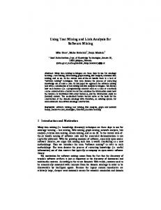
a new ISO/IEC 15504 standard and will be based on CMM, ISO 9001, Bootstrap and other well-known standards. A detailed description of the standards is given in Sect. 2.2 of the thesis. In CMM, achieving the next level of the maturity framework results in increasing the process capability of the organization. The first level of the CMM model (initial) is characterized by ad-hoc and occasionally chaotic processes; the second (repeatable) implies the existence of the process discipline repeating earlier successes; the third level (defined) means that the processes are modelled, documented, standardized and integrated to the organization; the fourth (managed) level is achieved when the software process and products are quantitatively understood and controlled; the fifth (optimizing) level enables a continuous process improvement from innovative ideas and technologies (for more details on the CMM and the CMMI models, see Sect. 2.2.2). So, the CMM was introduced for incrementally improving the maturity from the first (initial) level to the higher levels, see Fig. 1.1. The CMM achieved great industrial recognition; for example, nowadays, big enterprises use to require its contractors to be on the defined level of CMM (initially, it was a requirement of the US Department of Defense). Further, we focus on the first three maturity levels. 5 Optimizing 4 Managed 3 Defined 2 Repeatable 1 Initial
Figure 1.1: Capability Maturity Model
The Software Engineering Institute regularly publishes statistics about the organizations implementing CMM and their achievements in software process improvement in “Process Maturity Profile of the Software Community” [SEI06b] (similar statistics is published for CMMI also [SEI06a]). These statistics are based on the information from such appraisals as: CMM-Based Appraisals for Internal Process Improvement (CBA IPIs), Software Process Assessments (SPAs) and Standard CMMI Appraisal
4
CHAPTER 1. INTRODUCTION
Method for Process Improvement (SCAMPI). The first section of the profile is called “Current Status” and contains information about the levels of maturity of different organizations. The 2005 end-year profile conducted information about 1804 organizations, 996 participating companies and 8897 projects. So, 5.7% of the organizations are on the initial level, 39.6% are on the repeatable level and 37.4% on the defined level, see Fig. 1.2. 100% 90% 80% 70% 60% 50%
39.6%
40%
37.4%
30% 20% 10%
7.6%
5.7% Initial
Repeatable
Defined
9.8%
Managed Optimizing
Figure 1.2: Maturity Appraisal by Reporting Organizations
It means that 45.3% (5.7%+39.6%) of all the organizations do not have a modelled, documented and standardized process and, thus, have to derive it (i.e. to document, to standardize and to integrate a process model to the organization) to achieve the next maturity level. After looking at the key practices of the CMM [PWG+ 93], we can also interpret these statistics the other way: 82.7% of all organizations (5.7% + 39.6% + 37.4%) either do not have a modelled, documented and standardized process or they have just implemented it and continue working on its tailoring in the organization. Other interesting statistics in our context are the “Organizational Trends”, they contain the time needed by the organization to improve the process capability, see Fig. 1.3. If we take the right part of the graph, which contains the overall statistics from year 1987 till now, we see that it takes 23 months to go from the initial maturity level to the repeatable one, 20 months to go from repeatable to defined and 25 months to go from defined level to the next one. Thus, for an initial level organization, on the average, it takes 43 months (20 + 23) to come to the defined level and to get a
1.1. MOTIVATION
5
Figure 1.3: Time To Move Up
documented and standardized software process model. Thus, with the help of the statistics presented in this section, we come to a conclusion that plenty of organizations do not have documented and standardized software process models and it takes years to get them. Thus, along with the increasing importance of process technology and process-oriented view on business, there is a variety of unresolved issues, relevance of which cannot be overestimated.
1.1.2
Software Process Modelling
In this section, we discuss the software process models and methods used in the enterprises for designing the models. In the previous section, we learned that enterprises need a documented and standardized process model in order to improve the quality of their work. From the standpoint of a software process engineer, there is always a kind of a software process in an enterprise, but this process is usually not explicitly formulated and documented. Accordingly, the information about the process is often “hidden” in heads of particular practitioners or managers. Thus, the knowledge about the software process is implicit and also distributed among different people, while explicit documentation of the software process is essential for further process management and optimization.
6
CHAPTER 1. INTRODUCTION
Models and Reality The crucial question in the area of modelling in general and software process modelling in particular is: How do models relate to reality? In process modelling, we can distinguish between prescriptive and descriptive process models [Sca01, Wan00, Lon93]. Prescriptive models specify how processes should take place. Descriptive models specify the processes how they actually happen. After more than 30 years of software process research, people have gained a broad experience in prescriptive software process modelling and software lifecycle models [Roy87, Boe88, BT75, Gil81]. But there is a set of disadvantages in prescriptive process modelling especially concerning its practical applicability: first, models usually prescribe how a new software system should be developed; second, specific conditions of a specific software system are often ignored or generalized; third, rather often models describe an idealistic view on software development and can hardly prescribe the ways of eliminating the chaos which happens in practice. Descriptive process models, on the other hand, specify how particular software systems are being developed. Rather often, these models are developed under very specific settings and can hardly be applicable under other settings or serve as common modelling recommendations. For deriving common descriptive models, one must collect a lot of data about different software projects; usually, it is difficult to find out the sources of this data and to obtain it. Thus, there is a lack of process models that (1) reflect real-life scenarios, i.e. do not have discrepancies with reality and (2) are explicit and general enough to be used under different settings in different projects. Moreover, obtaining such models is possible only after having analysed huge amounts of data about software projects. Consequently, people need methods for obtaining and analysing software projects data and methods for deriving process models from it. Manual versus Automatic Modelling Another crucial modelling question is: Who designs the models and how is it done? In our context, this question can be put the following way: Are software process models designed manually (without software support) or semi-automatically (with the help of software)? The answer is: today, process engineers and managers in enterprises are almost always solving this problem without software support. It has a set of disadvantages: it is complicated, time-consuming, error-prone, and the results rapidly become obsolete;
1.1. MOTIVATION
7
the capabilities of human beings in detecting discrepancies between the actual processes and the process models are rather limited. Practitioners (developers, designers, quality assurance engineers) are usually not involved in process design, although they are the real experts in their parts of the process. So, information about the practical details of some parts of the process is often completely lost. Furthermore, process engineers usually can not simply start from scratch when defining explicit process models, but should take existing practices into account. Data about these practices can not be stored and effectively maintained only by process engineers without any automatic support. As a consequence, tool support is needed for designing the process models1 . Thus, today process models are designed without essential tool support, which enormously increases the complexity of tasks fulfilled by process engineers but does not lead to effective solutions.
1.1.3
Problem Statement
In this section, we summarize the topics discussed above. After analysing the statistics (see Sect. 1.1.1) and common experience in the area of software process modelling (see Sect. 1.1.2), we come to the following conclusions: • A great number of enterprises does not have documented and standardized software process models. It takes years for enterprises to document their processes and to create explicit software process models. • Designed models usually prescribe the desired behaviour and there are a lot of discrepancies between the actual processes and the models. • Existing practices are often not taken into account and there is no appropriate automatic support for considering them. • Practitioners (developers, designers, quality assurance engineers) are not involved in process design and there is no appropriate automatic support for involving them. • Without software support, process design becomes very complicated, expensive, time-consuming and error-prone task. 1
“Process Design” is a complicated and creative task and it can not be solved fully automatically.
But this should not be considered as a counter-argument against tool support. Quite the contrary, the work of managers and process engineers in the enterprises should be significantly simplified and improved with the help of an automatic approach.
8
CHAPTER 1. INTRODUCTION Altogether, there is a lack of automatic and formal approaches that support people
(process engineers, managers, designers) during process design phase – there is a lack of tool support for the designers.
1.2
Thesis Objectives
In this section, we outline the ideas and techniques, which are helpful for addressing the issues discussed above and, then, we set our objectives.
1.2.1
Process Mining
During the last years, workflow management technology is becoming ever more important [LR00, JBS97, vdAvH02]. It is a technology for modelling, enacting and analysing business processes with computer support. Nowadays, this technology is supported not only by Workflow Management Systems (WfMS), but by Enterprise Resource Planning (ERP), Customer Relationship Management (CRM), Business to Business (B2B) systems and others, such systems are also called Process-Aware Information Systems (PAIS). Workflow design is a vital and creative task in this area. Today, workflow research is inspired by the need of enterprises to support dynamic processes. So, the goal is not to produce structured processes (old “workflow paradigm”), but to support, monitor and influence changing processes. In this sense, there is much in common between the software process design problems presented in Sect. 1.1.3 and the workflow design problems. Workflow mining or Process Mining, as it is often referred to in the respective literature, is a promising research area, which aims at supporting the workflow design [vdAWM04]. Modern PAIS systems record enormous amount of data in the form of logs. Workflow mining algorithms use the logs of workflow activities for discovering workflow models. These activity logs contain information about process executions as they take place. Nowadays, the logs are provided by most workflow management systems. Workflow mining suggests a new perspective on the workflow design lifecycle [vdAvDH+ 03]. Traditional design life-cycle approaches begin with “workflow design” and “workflow configuration”, then they continue with “workflow enactment” and finish with “workflow diagnosis”, see Fig. 1.4. During the first two phases, a business process is designed by a process engineer, afterwards a workflow management system is configured according to the design. In the enactment phase, workflows (process instances)
1.2. THESIS OBJECTIVES
9
st
st a
rt
Diagnosis
Diagnosis
ar t
Workflow Life-cycle
Enactment
Design
Enactment
Design
Configuration
Configuration
Figure 1.4: Traditional Life-Cycle
Workflow Life-cycle
Figure 1.5: Mining Life-Cycle
are executed. In the diagnosis phase, information about executed workflows is analysed. However, in the traditional approach, the focus is on the design and configuration phases. Diagnosis information is often neglected. The workflow mining approach starts with the diagnosis phase, see Fig. 1.5. So, workflow runtime information is used for creating the workflow design, which reflects the actual situation in the company and is used in the next phases of the workflow life-cycle.
1.2.2
Software Repositories
A critical question in the area of process mining is: Where do the logs come from? In the business process management domain, when a workflow management system is there, the logs are usually available. But what about the software process modelling domain, the problems of which we are going to solve? Where do we take the logs, when a process management system is not there? What are the real sources of the logs? How do these logs look like, do they also contain activities? Having studied modern software engineering environments (SEEs), we discovered the following: firstly, most companies do not have process management systems (which is also proved by the CMM statistics); secondly, the systems used in SEEs do not provide activity logs. But, the most important and motivating point that was understood is: nowadays, such software repositories as software configuration management (SCM) systems, defect repositories, mailing lists, and discussion forums comprise essential parts of software engineering environments. These repositories are usually used even when no precise definitions of processes exist. Furthermore, using software repositories and especially SCM systems is recommended by modern soft-
10
CHAPTER 1. INTRODUCTION
ware process improvement standards. For example, in CMM, one key process area on the repeatable level is “Software Configuration Management”. Within this key process area, software configuration management system must be introduced and used in the company and an organizational policy for using this system must be specified [PWG+ 93]. Practically, software repositories are standard components of modern SEEs both in open-source and in commercial environments. In the case of SCM, systems are aware of documents and changes made on them; but, they are not aware of the activities of the underlying processes. Therefore, the audit information about software projects provided by SCM systems in a form of document logs (they contain information about the executions of software processes) can be used for supporting process engineers in process design and for introducing process management systems to companies. As mentioned above, not only SCM systems, but also other software repositories are playing an important role in software development; it is especially noticeable in the open source software (OSS) domain. Thus, all these repositories can be used for tracking the progress of software projects. Hence, software repositories are important for supporting process design and they should be used for deriving useful information about software processes and projects.
1.2.3
Objective and Tasks
In this section, we determine the objective of the thesis. The objective ensues from the set of problems in the area of software process modelling described in Sect. 1.1.3, from the benefits of process mining for workflow design described in Sect. 1.2.1 and from the relevance and viability of software repositories described in Sect. 1.2.2. The main objective is to develop a workflow mining approach for deriving process models from document management information and • to apply the approach to the domain of software process modelling; • to assume that the software company is on the repeatable CMM level and that software repositories including an SCM system are introduced to the company; • to use the document logs obtained from the software repositories as an input and generate formal software process models as an output. So, the global perspective of our approach is to provide an automatic support for achieving the third (defined) CMM level once the second (repeatable) level is reached, see Fig. 1.6.
1.3. APPLICATIONS IN DIFFERENT AREAS
Workflow Mining Approach
3 Defined
11
Process Model
2 Repeatable Software Repositories
Figure 1.6: Objective: New Workflow Mining Approach
This objective should be achieved by fulfilling the following tasks: • Analyse and generalize information available in the logs of software repositories, focus on the software configuration management systems especially. Also, analyse the document management systems used in other application domains. • Develop an approach and algorithms for discovering formal process models from the logs. Consider existing experience from the areas of workflow mining and process synthesis. • Use a formalism with precise semantics, which supports all the basic process modelling patterns and for which there is a considerable algorithmic and tool support for model analysis, verification and simulation (e.g. Petri nets [RR98] and/or Transition Systems [HMU00]). • Find methods, which support transformation of the resulting models (Petri nets) to the other widespread formalisms, like EPCs [KNS92] or UML Activity Diagrams [OMG03]. • Develop a research prototype and evaluate the algorithms on practical examples with the help of this prototype.
1.3
Applications in different Areas
In our Motivation Section (see Sect. 1.1), we examined the area of software engineering and software processes, which is the main focus of our research. But generally, looking at other research domains, such as mechanical engineering, electrical
12
CHAPTER 1. INTRODUCTION
engineering, mechatronics, telecommunications and networks, we realize that similar problems and objectives are relevant to these domains too. Such areas as Product Data Management (PDM) and Product Lifecycle Management (PLM), Enterprise Resource Planning (ERP), Supply Chain Management (SupCM) and Customer Relationship Management (CRM) can benefit from our approach; it can be used for deriving process models from the audit information available in these systems. In this thesis, we also briefly look into these areas. For example, Product Data Management (PDM) is the discipline of controlling the evolution of a product design and all related product data during the full product life cycle [DAC+ ]. Correspondingly, PDM system is a tool for managing data and processes. In this context, Software Configuration Management can be regarded as a subarea of PDM, since it deals with a specific type of products, namely software. During the last decades, the area of PDM has expanded to the collaborative Product Definition management (cPDm) [CIM01]. cPDm manages the complete product definition lifecycle, including mechanical, electronic, software, and documentation components and the processes used during the lifecycle. So, cPDm includes such technologies as PDM, visualization, enterprise application integration (EAI), and others. Experience in the area of PDM has shown that, during the product life-cycle, many workflows are created for controlling changes, reviewing and other purposes. These ad-hoc workflows have to be formalized, documented and saved in the system. Additionally, there are often discrepancies between the process design and the real workflows. Since storing the audit information is a standard practice in this area, PDM logs are available for analysis. These logs can be used for mining the production processes. Thus, the approach and algorithms defined in the next chapters of this thesis are also relevant for this area. It is worth mentioning here, that auditing and process management capabilities are essential also in ERP, SupCM and CRM areas and, thus, the approach should be also applicable there.
1.4
Roadmap
Our research is inspired by the ideas from two significant research areas, such as software process modelling and business process management, therefore, we have to carefully specify the relevant background from both areas and to eliminate the uncertainties, it is done in Chapter 2. We also define the background of modelling
1.4. ROADMAP
13
formalisms in the same chapter. In Chapter 3, we present our process modelling approach called Incremental Workflow Mining. We start with an architecture of software engineering environments, where the approach can be applied. Then, the sources of input information are analysed and the main scheme of our incremental approach is described. The idea of our mining algorithms is presented in this chapter on a general level using several small examples. Chapter 4 contains the details of the algorithms and models of our approach. Systematically, we go through the steps of the approach and present our algorithms, their formalizations and derived models. Implementations of these algorithms constitute our incremental workflow mining research prototype and plugins for the process mining framework. The research prototype and the plugin are used for evaluating the approach on three relatively big examples based on the open-source software repositories and information from students’ software repositories respectively. These evaluation details are covered in Chapter 5 ; the practical output of our algorithms is also presented in this chapter. In Chapter 6, we discuss the relation to existing work and point out our new contributions to both fields: process mining and software process modelling. In the last chapter, we present the thesis contributions and summarize open issues and future work.
14
CHAPTER 1. INTRODUCTION
Chapter 2
Relevant Background In this chapter, we examine the background knowledge that comes from the areas of software process modelling and business process management and define the main terms used in these domains1 . The described areas deal with processes. According to the Oxford dictionary [SW89], a process is “something that goes on or is carried on; a continuous action, or series of actions or events; a course or method of action, proceeding, procedure”.
2.1
Business Process Management and Workflow Management
In this section, we go into the details of the areas of business process management and workflow management. In the literature on business process management, there are many different proposals using different terms, many of them are not consistent and no terminology is fully accepted. Our definitions and terminology are strongly influenced by [vdAvH02, DvdAtH05, LR00, JBS97, Hol95]. The terminology and the ontology of the domain was also discussed in our work [AKR05a, AKR05b, AKR06].
2.1.1
Business Process Management
In this section, we describe the area of Business Process Management (BPM). The Workflow Management Coalition defines business process as follows: “a set of one or more linked procedures or activities which collectively realise a business objective or policy goal, normally within the context of an organizational structure defining 1
A discussion on process mining is held in the next chapters, where we describe our approach and
related work.
15
16
CHAPTER 2. RELEVANT BACKGROUND
functional roles and relationships” [WfM99]. Another definition is given by v. d. Aalst and v. Hee [vdAvH02]: “business process is one focused upon the production of particular products. These may be either physical products, such as an aircraft or bridge, or less tangible ones such as a design, a consultation paper, or an assessment. In other words, the product can also be a service”. Taking both definitions into account, we realize that a business process is a process, which has an objective and is focused on production of products or services; secondly, it takes place within an organization. The given definitions are very general, but they answer the generality of purposes and applications of business processes. Business process management is applied in many areas, such as business administration, economics and management, psychology and sociology, mechanical engineering, network engineering and others. During a long time, business processes were managed manually (by people). People planned and structured their work and decided on which phases of their working process they need some computer support. During the last years, the situation has changed, information systems provide new efficient ways of organizing business processes with the aid of computers. Software is used for managing processes and organizing the work in the company. Often it is called a shift from “data-aware” information systems to “process-aware” information systems (PAIS).
2.1.2
Workflow Management
An example of such a PAIS is a Workflow Management System (WfMS). The Workflow Management Coalition states that workflow is “The computerised facilitation or automation of a business process, in whole or part.” [Hol95]. It means that we start speaking about workflows instead of business processes, when they are managed by software. So, the term “business process” has a more general meaning then the term “workflow”, but since in this thesis we are speaking about software-based management of processes, these terms are used interchangeably. Workflow Management System is defined as follows: “A system that defines, creates and manages the execution of workflows through the use of software, running on one or more workflow engines, which is able to interpret the process definition, interact with workflow participants and, where required, invoke the use of IT tools and applications.” [WfM99]. From this definition, we deduce the following general use cases of the WfMS: • Modelling (designing) business processes.
2.1. BUSINESS PROCESS MANAGEMENT AND WORKFLOW MANAGEMENT17 • Executing business processes. • Managing process executions. • Interacting with workflow participants. • Interacting with other applications. Now, let us systematically go through these use cases. WfMS must support modelling business processes. So, we distinguish between the terms “business process” and “business process model” (respectively “workflow” and “workflow model”). Now, since we are dealing with workflows and software, we can give more concrete definitions, which correspond to a software engineering view on WfMS. The following definitions resulted from the research in the AMFIBIA project and were formulated in our papers [AKR05a, AKR05b, AKR06]: A business process consists of a set of activities that are executed in some enterprise or administration according to some rules in order to achieve certain goals. An activity is a description of a piece of work that forms one logical step within a business process. A business process model is a more or less formal and more or less detailed description of the persons and artefacts involved in the execution of a particular business process and its activities as well as of the rules governing their execution. A business process model consists of tasks. A business process is an instance of a business process model and an activity is an instance of a task. A business process is also often referred to as case in the respective Class Diagram
2006/07/10
literature. A meta-model describing the introduced terms is shown in Fig. 2.1 as a UML class diagram. Business Process (Case)
Business Process Model
*
1
*
* Task
Activity
1
*
Figure 2.1: Business Process Model and Case
Modern WfMS usually include also model analysis tools. They check the semantic correctness of the process definitions, make verification and simulation of the models.
18
CHAPTER 2. RELEVANT BACKGROUND
Analysis should precede the execution of the models. Executing business processes and managing process executions are the other use cases supported by a WfMS. The component of the WfMS which fulfils these operations is often called workflow enactment service, it makes up the heart of the workflow management system. This service can be implemented by one or several workflow engines. Workflow engine deals with the actual management of workflows. It creates cases, activities, matches resources for these activities, makes resource assignment, matches information for the activities, launches external applications, records all the historical data about the case execution and checks its consistency. WfMS must also support interaction with workflow participants. Participants contact the system using workflow client applications (process designers are not workflow participants, they contact the system using the process definition tools). Every participant has a worklist. A worklist contains a set of work items. A work item is the combination of a case and a task which is about to be carried out. As soon as an employee decides to carry out a work item from his worklist, it becomes an activity. Another set of workflow client applications is provided to managers for administrative and monitoring purposes. Using these applications, people see the current state of work and the history. Since nowadays, a WfMS can be a part of a bigger information system or it can be built as a distributed application or it has to interact with the other WfMS, another use case is integration with the other applications. Thus, the main concepts and use cases of WfMS are summarized in the Workflow Reference Model [Hol95], which represents the recommended architecture of a WfMS, see Fig. 2.2. There are a lot of other use cases for WfMS, here we present only the main concepts and terminology, additional details can be found in the workflow reference model of WfMC and the books referenced in the beginning of this chapter. The reference workflow management system consists of the workflow engine in the middle and of five interfaces between the engine and the applications and tools. Interface 1 connects process design tools with the workflow enactment service. Interface 2 is used for the interaction with the client applications, e.g. with worklists. Interface 3 is used for executing external applications. Interface 4 enables the work exchange between different workflow systems. Interface 5 is used by the administration and monitoring tools. Every interface should be achieved using a Workflow Application Programming Interface (WAPI). WAPI is provided to the external tools and applications by the workflow engine. Often, WfMS is implemented as a client/server or a
2.1. BUSINESS PROCESS MANAGEMENT AND WORKFLOW MANAGEMENT19
Process Definition Tools Interface 1 Interface 5
Workflow API and Interchange formats
Interface 4 Other Workflow Enactment Service(s)
Workflow Enactment Service
Administration & Monitoring Tools
Workflow Engine(s)
Workflow Engine(s)
Interface 2 Workflow Client Applications
Interface 3
Invoked Applications
Figure 2.2: Workflow Reference Model [Hol95]
multi-tier architecture, where a workflow engine is a server or an application server respectively, see Fig. 2.3.
Client Side
Applications And Tools
Interfaces Workflow Engine
Server Side Database
Figure 2.3: Workflow Management System Architecture
The modern successful and rapidly developing workflow market contains different types of workflow management systems and business process modelling tools. Here, we refer to the following WfMSs: iProcess suite from Tibco (www.staffware.com) is one of the most widespread WfMSs, IBM WebSphere (www-306.ibm.com/software/
20
CHAPTER 2. RELEVANT BACKGROUND
websphere/) is a huge platform combining BPM and SOA, COSA (www.cosa-bpm. de) is a BPM solution based on Petri nets, Domino Workflow from Lotus, I-Flow from Fujitsu, HP ChangeEngine from HP, SAP NetWeaver from SAP and many others. In the area of business process modelling, such solutions as ARIS [Sch00] (a platform and an architecture for business process modelling) from IDS Scheer and ADONIS (www.boc-eu.com) should be also mentioned. In this section, we introduced the main terms in the area of workflow management and made the connection between the concepts of business processes and the information technology used for implementing them.
2.1.3
Models and Aspects of Business Processes
Correct and efficient business process modelling, which reflects the real business cases, is a keystone of a successful workflow management in the enterprise. Research in this area gives motivation for this thesis, our special interest was discussed in Sect. 1.2.1. Generally, business process models are used for different purposes: • Documentation of the business process. • Collaborative design of the business process. • Communication and teaching of the business process. • Analysis and verification of the business process. • Optimisation and re-engineering of the business process. • Computer support and execution of the business process (see Sect. 2.1.2). Business processes play an extensive role in managing the business in organizations, as described in Sect. 2.1.1. Therefore, practically, business process models do not contain only information about the order of tasks (control flow), but also the data about the required and produced documents, the resources that can execute the tasks and the strategy of their assignment, the structure of tasks and their functional relations and many other information. So, it turns out that several aspects 2 of business processes can be distinguished when modelling business processes; and these aspects can be modelled more or less independently from each other, see Fig. 2.4. 2
Such terms as “perspective” or “view” are also often used instead of the term “aspect”. We use
this term, because we consider the relation between business process aspects and aspect-oriented programming and modelling to be very important.
2.1. BUSINESS PROCESS MANAGEMENT AND WORKFLOW MANAGEMENT21
Assignment Organization
Authorization Authentication
Process
Information
Control
Transaction
Figure 2.4: Aspects of Business Processes
Here, we will not go into the details of modelling business process aspects, since it is a separate area of research, which goes beyond the background knowledge, for details about the integration of aspects see [AKR05a, AKR05b]. Here, we use aspects for better explaining the models of business processes. So, the basic aspects are the following: Control Aspect: This aspect deals with the dynamic behaviour of the business process. It defines the tasks resp. activities of a process and the order in which they are executed. The definitions of tasks and activities were given already in Sect. 2.1.2. Information Aspect: This aspect deals with the data and documents used in the business process. It defines the structure of the data and documents that are used and changed within the tasks of a process and how they are propagated between tasks of a business process - resp. between the activities of a case. A document here is an artefact representing some piece of information. The information aspect of a business process basically defines the structure of the involved documents and their relation. Similar to processes and cases, tasks and activities, we distinguish between document instances and document types, where document type defines the structure of a document instance. Organization Aspect: This aspect deals with the organization structure. It defines the roles, positions, agents, organization units and resources that are involved
22
CHAPTER 2. RELEVANT BACKGROUND in a business process. An organization unit is a group of some people organized for some purpose. An organization position is an atomic organization unit. A role is also defined as a group of resources; every resource in this group has specific skills. The difference between organization units and roles is: organization units define the organizational structure, roles define the functional structure. A resource – person, machine or application which is assigned a task. Agent is a human resource. Resources required for some task are assigned via their positions and/or roles. The business process modelling area also uses to deal with other aspects including
transaction aspect, assignment aspect, and authentication aspect, see Fig. 2.4; as mentioned before, detailed description of these aspects is out of the scope of this thesis. Business process models are usually defined in a textual or graphical form in a formal language notation. Different formalisms are used for modelling different aspects. Petri Nets [Aal98] and EPCs [KNS92] are used for modelling the control aspect; for the information aspect, people use ER Diagrams [Che76], UML Class Diagrams [OMG03] and others; for the organization aspect people are using Organigramms, etc. Some notations support several aspects, e.g. UML Activity Diagrams [OMG03], BPMN [OMG06] and BPEL [ADG+ 03]. One of the important criteria for selecting an appropriate formalism is whether it can be processed by the engine of a workflow management system. In this section, we proposed an aspect-oriented view on process modelling, see Fig. 2.5. We consider this view to be useful for understanding the essence of business process modelling, for developing common formats, for exchanging models between different companies, for integrating new aspects and implementing workflow engines.
2.2
Software Process Modelling and Improvement
In this section, we describe the area of software processes. The software process defines the way in which the software engineering is organized, managed, measured, supported and improved [DKW99a]. This field has grown up in the 80ties to address the increasing complexity and criticality of software development activities. Historically, this research has started at that time, when researchers and practitioners have realized that software engineering is a collaborative, creative, and complex task and not just creation of tools and new languages. When developing software, people
2.2. SOFTWARE PROCESS MODELLING AND IMPROVEMENT ER Diagrams
Class Diagrams
Information Aspect
23
Organigramms
Organization Aspect
Business Process
Control Aspect
Petri Nets
EPCs
Figure 2.5: Aspect-oriented View on Process Modelling
have to manage and concern such issues as technology, methodology, social and organizational behaviour, business and market. All these issues directly influence the quality of a software product. Thus, the software process is defined the following way: “the coherent set of policies, organizational structures, technologies, procedures, and artefacts that are needed to conceive, develop, deploy, and maintain a software product.” [Fug00]. Comparing this definition to the definition of business process given in Sect. 2.1.1, we realize that the software product in the case of the software process is what was called the objective in the case of the business process. Originally, the definition of a business process was more general then the definition of a software process; but, nowadays, taking into account the growing popularity of software-intensive and embedded system, where software process can not be considered separately from the other business processes, this difference is becoming less and less visible. Earlier, during the 60ties and the 70ties, before the software process research was started, people defined the software lifecycles, such as waterfall, incremental development, prototype-based development [Roy87, Boe88, LB03]. Actually, lifecycles defined different stages in the lifetime of a software product and the guidelines for carrying out these stages. Basically, lifecycles can be considered as software processes, but on a rather abstract and imprecise level. Today, the concept of lifecycles is often
24
CHAPTER 2. RELEVANT BACKGROUND
considered as an idealised concept, which has limited practical applicability. In the next sections, we discuss the most important areas of the software process research; this discussion is influenced by [Fug00, DKW99b, Ost87, CKO92, FH93, Gru02].
2.2.1
Software Process Models and Engineering Environments
In this section, we discuss the area of research, which deals with models of software processes and their enactment. During the years of research, people created a set of Process Modelling Languages (PMLs) and modelling formalisms. A PML is a language that expresses software development processes in a form of a process model, i.e. in a computer-internal description. It has to be possible to model such process elements as tasks, roles, tools and agents in a PML. There are different views on the process models (the idea of views is similar to the idea of aspects in business process modelling presented in Sect. 2.1.3). Typical views are: Activity Model: It focuses on the structure, properties, and relations of activities. Product Model: It describes the types, structure and properties of the software items (documents) of a process. Resource Model: It describes the resources needed or supplied to the process. The problems of views separation and integration are important in the area of software processes as well as in the area of business processes. Like business processes, software processes play an extensive role in a company and, thus, have to manage not only correct order of tasks execution, but people, information, business change and evolution, etc. So, the main elements of a software process are the following: Activity: It is a process step, operating on software artefacts and coupled to a human agent and to external production tools. Activities can be on different abstraction levels. Product: It is a software artefact which is persistent and versioned, and which can be simple or composite. These artefacts describe software products: design documents, user documents, test data, etc. Role: A Role describes the rights and responsibilities of the human.
2.2. SOFTWARE PROCESS MODELLING AND IMPROVEMENT
25
Human: Humans are process agents or process performers. Humans undertake roles. Organization: Organization is a group of humans who have relationships with each other and to process elements. Tool: Tools are used for software production. People are using such tools as compilers, parsers, textual editors and CASE tools. Class Diagram
2006/07/17
The relationships between these elements are summarized in Fig. 2.6. has sub
has sub has input Activity
Organization
has output
Product
employs
needs
Tool
contains
Performer
Role plays
Figure 2.6: Basic Software Process Elements
An environment that supports the creation and exploitation of software process models is often called Process-centered Software Engineering Environment (PSEE). So, PSEEs are based on PMLs. There is a set of good surveys of PSEEs and PMLs, we establish our brief overview of PSEEs on some of them [DKW99b, Gru02, ACF97, GJ96]. Our goal is to show several relevant ideas from this area. OIKOS The OIKOS [ACM90, MA94] is an environment for software development. The idea and main goal of OIKOS is to ease the construction of PSEEs. The other goals are comprehension and documentation of software processes. It offers two PMLs: Limbo and Pat´e. Limbo is a high-level process specification and design language; there is a graphical editor for Limbo. Pat´e is and executable distributed language. A Limbo specification is stepwise refined into the Pat´e executable code. Both languages are
26
CHAPTER 2. RELEVANT BACKGROUND
based on concurrent logic and Prolog. The OIKOS process model can be considered as a communication of concurrent agents. EPOS The emphasis of EPOS [CHL+ 94] is on flexible and evolving process assistance for software development. EPOS can manage “soft” process assistance as well as “hard” process control. EPOS process models are expressed in SPELL, an object-oriented and concurrent modelling language, it has Prolog as a subset. Activity networks in SPELL can express both goal-oriented process models, using static rules and constraints for automatic network planning, as well as activity-oriented process models, using dynamic pre- and postconditions and scripts. The models are stored in a versioned database called EPOS-DB. Merlin In Merlin [JPSW94], process modelling is performed on two different levels: the first level is visible to the process-engineer, it uses the ESCAPE design language; second level is used for enacting the process design, it is based on a Prolog-like programming language. ESCAPE (Extended Entity Relationship Models and Statecharts Combined for Advanced Process Engineering) is a graphical language which contains the following models: object model is based on EER-model, it is used to specify the structural aspects of process, such as document types, activities, etc.; coordination model is based on statecharts and specifies the behaviour of a process; organizational model specifies roles and responsibilities, i.e. organizational aspect of a process. Thus, the structuring of process is reached through a separation of concerns, which makes the design understandable and applicable. Prolog enactment is reached by mapping the ESCAPE design to the Prolog rules. SPADE The SPADE [BFGL94] is an environment for process analysis, design and enactment. The main concept of the project is the adoption of extended Petri nets, augmented with specific object-oriented constructs to support product modelling. SLANG is the PML of SPADE, it is used to support process analysis and design, its graphical syntax (based on traditional Petri nets) is easy to learn and to use. SLANG is integrated with the O2 object-oriented database which acts as a repository for both process models and process products.
2.2. SOFTWARE PROCESS MODELLING AND IMPROVEMENT
27
FUNSOFT Nets Another approach for modelling and analysing software processes is the FUNSOFT Nets [EG91] (the approach was also used in the business process modelling area). This approach adopts high-level Petri nets for describing software process models. The semantics of FUNSOFT nets is defined in terms of Pr/T (Predicate/Transition) nets. Therefore, it allows for standard analysis and simulation techniques approved for Predicate/Transition nets. As is easy to see, many PSEEs utilize the concepts of Prolog and graphical formal specification languages like Petri nets. We are also using these concepts in this thesis, Petri nets are used as the main process modelling formalism and Prolog is used for implementing our research prototype.
2.2.2
Software Process Improvement
The background of software process improvement was used already for the motivation for the thesis in Sect. 1.1.1. CMM and CMMI were described there. However, the initiatives in this area can be divided into three directions [DKW99b]: • Definition of standard processes. These focus on quality standards. • Definition of assessment methods. These focus on measuring process maturity and its levels. • Definition of improvement methods. These are based on the idea that process improvement can be accomplished by learning from the previous experiences. In the area of standard processes, the International Standard Organization (ISO) (www.iso.org) supplies a family of standards, namely ISO 9000, which define the phases of the production and delivery processes. An organization has to follow these phases to produce a high-quality product. These standards are applicable to all production processes and its specialization ISO 9000-3 – only to the software development. Yet, ISO 12207 is more concrete than ISO 9000 in respect to software engineering processes, it includes mandatory processes, tasks and activities. In Europe, the European Space Agency (ESA) defines standards, guidelines and recommendations concerning the software and concerning the software project management procedures. A very well-known assessment method is the Capability Maturity Model (CMM) ( see Sect. 1.1.1) developed by SEI, the work on it was motivated by Humphrey [Hum89]. The process assessment program starts with training the assessment team,
28
CHAPTER 2. RELEVANT BACKGROUND
then the project members complete the questionnaires and participate in the interviews. These questionnaires and interviews are used for preparing the report identifying the weaknesses of the organization. In the European Union within the Bootstrap [Kuv95] project, a framework for assessing industries and promoting process improvement was defined. Basically, Bootstrap is an improvement of the SEI method taking the ideas from the ISO 9000-3 guidelines into account. The Software Process Improvement and Capability dEtermination (SPICE) standard [Rou95] funded by the International Committee on Software Engineering Standards has the goal to build an international standard for software process assessment. It uses the knowledge acquired in CMM, Bootstrap and ISO standards. The result of this project is the new ISO 15504 standard. In the context of software process improvement, the Quality Improvement Paradigm [BCM+ 92, Bas93] presents the basic idea that process improvement is a continuous process. Such methods as Goal/Question/Metric (GQM) and Experience Factory Organization are used for guiding the process execution and structuring the organizational activities. This approach takes previous experiences into account. Along with the CMM, the SEI developed a Personal Software Process (PSP) and Team Software Process (TSP) [Hum05b, Hum05a], they are aimed at guiding and improving the productivity of individual software engineers or of small software engineering teams. PSP and TSP apply many considerations of the CMM. The SEI provides also positive practical evaluations of both approaches. Another approach to mention is the Total Quality Management (TQM) [Fei91a, Ban93], which is a general paradigm guiding organizations and focusing on quality. The idea behind TQM is that quality is not only related to product but to the production process and that the management of quality implies continuous and never-ending process improvement. In this Section, we described the set of well-known process improvement standards, which are widely accepted both in science and in industry. In this thesis, we suppose that our automatic method, which uses software repositories for deriving information about software processes and for making process models explicit, can be helpful for process assessment and improvement teams when dealing with rapidly changing software development processes.
2.2.3
Software Configuration Management
Software Configuration Management (SCM) is the discipline of controlling the evolution of a software product. As mentioned in Sect. 1.2.2, using SCM is recommended
2.2. SOFTWARE PROCESS MODELLING AND IMPROVEMENT
29
by software process improvement standards, e.g. CMM. Moreover, SCM plays a key role in achieving ISO 9000 conformance. In this section, we use the following papers as a background [EC94, Fei91b, FZ99, DAC+ , EFM98, CW98a]. Apparently, nowadays it is almost impossible to work without SCM systems, since software engineering implies a collaborative way of work that must be appropriately controlled. The Association of Swedish Engineering Industries defines Configuration Management as a “controlled way to manage the development and modifications of systems and products, during their entire life cycle.” In the respective literature, people use to examine the SCM area from two different perspectives: management and development. From the management perspective, SCM controls the development of products by the identification of product components and control of their changes. The main activities comprising the management perspective are: configuration identification, configuration control and audit, and configuration status accounting. From the developer perspective, SCM offers tool support for maintaining the software product, storing its history, providing stable development environment and coordinating simultaneous product changes. The SCM standards are described on a rather conceptual level, but from the developers perspective, an SCM system must provide the following functionality: version management and configuration selection, concurrent development, build and release management, workspace management, change management. Head
1
2
3
4
5 Release 1
Branch 1
n
6
7
- Revision
Figure 2.7: Revisions Graph
Version management is the key aspect of SCM. A software element put under the version control is called a configuration item (CI). A stable issue of a CI’s content is called a version. The background idea of version management is simple: each time a CI (file) is changed a revision is created. Configuration item evolves as a sequence of revisions. Development can be also organized in parallel lines called branches. Branches can be merged into new revisions. An example presenting the graph model of revisions and branches is shown in Fig. 2.7. Along with version management, SCM
30
CHAPTER 2. RELEVANT BACKGROUND
must support also configuration selection (i.e. a rule-based mechanism for selecting desired configuration items). Baseline is a particular configuration serving as a basis for further development. Release is also a configuration delivered to a customer. SCM Repository
File System checkout
Doc A
checkin
Doc A
Figure 2.8: Checkin/Checkout Model
Concurrent development is the major advantage of using an SCM. The team members can work in parallel, which is extremely critical in the software engineering area. Users work with the SCM repository and with the file system. Users retrieve a version of a file from the repository using the checkout operation, then they work with them in the file system. Modified files are stored back into the repository using the checkin operation, see Fig. 2.8. For concurrent development an SCM should support synchronization of concurrent changes: the system can either lock edited files for one user (pessimistic approach) or allow simultaneous changes of the same file, but then SCM has to detect conflicts during the checkin (optimistic approach). Build management supports collecting code and documents for particular release and using build tools ; release management provides identification and organization of all the configuration items for the release. Workspace management deals with the user interface of the SCM system. Workspace works as a sandbox, where developers work in isolation, but still controlled by the SCM. Change management handles the changes in a system, e.g. errors, improvements, refactoring; change management is usually achieved with the aid of separate tools supplied together with the SCM. A great variety of tools was developed in the SCM area. The spectrum ranges from very small specific tools like SCCS [Roc75] and RCS [Tic85] (support mostly version control) to huge integrated systems like ClearCase (http://www-306.ibm. com/software/awdtools/clearcase/). In this thesis, for our experiments we use such open-source SCM systems as CVS [Fog99] and Subversion. In this section, we presented only the most relevant background ideas from the
2.3. MODELLING FORMALISMS
31
area of SCM, additional details can be found in the literature listed in the beginning of this section. The most important functionality in our context is providing the revision history in the form of logs of checkins and checkouts, further details are described in Chapter 3 on concrete examples.
2.3
Modelling Formalisms
In this section, we present the main definitions of the modelling formalisms used in the rest of the thesis.
2.3.1
Transition Systems
Transition system (TS) is a special automaton, which has no outputs. In mathematics, TS is sometimes called semiautomaton. Transition systems are often used for specification and verification of complex systems in a variety of application domains including embedded systems and control engineering, telecommunication networks and protocols, software and process engineering. Further, we give a definition of a transition system, which is based on [NRT92, CKLY98]: Definition 2.3.1 (Transition System). A transition system (TS) is a tuple T S = (S, E, T, sin ), where 1. S is a set of states, 2. E is a set of events (also often called labels), 3. T ⊆ S × E × S is a transition relation, 4. sin is an initial state e
The elements of T are called transitions and are often denoted as s → s0 instead of (s, e, s0 ). A transition system is finite if S and E are finite. In the sequel, we will consider only finite transition systems. A TS is called deterministic if for a state s e
and a label e there can be at most one state s0 , such that s → s0 . e
The system starts in an initial state; there is a transition s → s0 if the system can change the state from s to s0 on event e. We also define a reachability relation T ∗ on the transition system: it is a transitive closure of the transition relation T . Thus, state s0 is reachable from s in T if there is a sequence of transitions σ =
32
CHAPTER 2. RELEVANT BACKGROUND σ
∗
(s, e1 , s1 ) . . . (sk , ek , s0 ), this is denoted as s → s0 or s → s0 . Also, each state is reachable from itself, so, in general, the sequence of transitions can be empty. Furthermore, we will consider transitions systems that satisfy the following basic axioms: A1. No self-loops: ∀(s, e, s0 ) ∈ T : s 6= s0 A2. No multiple arcs between a pair of states: ∀(s, e1 , s1 ), (s, e2 , s2 ) ∈ T : (s1 = s2 ⇒ e1 = e2 ) A3. Every event has an occurrence: ∀e ∈ E : ∃(s, e, s0 ) ∈ T ∗
A4. Every state is reachable from the initial state: ∀s ∈ S : sin → s In special cases, we will also deal with transition systems with self-loops (they satisfy axioms A2,A3,A4). An example of a simple transition system with 5 states, 3 events and 5 transitions is shown in Fig. 2.9. s1 a
b
s2
s3 b
a s4 c s5
Figure 2.9: Transition System
Definition 2.3.2 (Transition System Isomorphism). Two Transition Systems T S1 = (S1 , E1 , T1 , sin1 ) and T S2 = (S2 , E2 , T2 , sin2 ) are isomorphic if there exist two bijections fS : S1 −→ S2 and fE : E1 −→ E2 such that sin2 = fS (sin1 ) and (s, e, s0 ) ∈ T1 if and only if (fS (s), fE (e), fS (s0 )) ∈ T2 for all s, s0 ∈ S and e ∈ E. Rather often, we consider isomorphism of a TS and a minimized version of a TS. We use also split-isomorphism. Transition systems T S1 and T S2 are split-isomorphic if there is such a transition system T S that:
2.3. MODELLING FORMALISMS
33
1. the underlying graphs of T S1 , T S2 and T S are isomorphic, 2. labels in T S1 and T S2 are two different enumerations of events in T S The enumeration assigns different instance numbers to the events. For example, two arcs labeled with an event a in T S1 can be labelled as a1 and a2 in T S2 . The corresponding operation is called splitting. Thus, we have sketched three notions of equivalence: isomorphism of TS, isomorphism with a minimized TS and split-isomorphism. These notions guarantee that two equivalent TSs are bi-similar. For further details about split-isomorphism and bi-simulation, we refer to [Mil82, CKLY95].
2.3.2
Petri Nets and Workflow Nets
In the thesis, we use Place/Transition nets (P/T nets), which is a class of Petri nets [Pet62, Rei87, RR98, Mur89]. Here, we start with the basic definitions: Nets Definition 2.3.3 (Net). A net N is a tuple (P, T, F ), which consists of two sets P and T , such that T ∩ P = ∅ and a relation F ⊆ (P × T ) ∪ (T × P ). An element p ∈ P is called place, an element t ∈ T is called transition, and f ∈ F is called arc.
F is called flow relation. Further, we consider only finite nets, i.e.
nets with finite sets of places and transitions. Places and transitions together are also called elements of the net or nodes. A node x is an input node of a node y if there is a directed arc from x to y, i.e. (x, y) ∈ F or xF y for short. An example of a net is presented in Fig. 2.10. This net contains 5 places 3 transitions and 7 arcs; places are represented as circles and transitions as rectangles respectively. p1
p3 t1
p2
p5 p4
t3
t2
Figure 2.10: Net
34
CHAPTER 2. RELEVANT BACKGROUND
Definition 2.3.4 (Pre-set and Post-set). Let N = (P, T, F ) be a net and x ∈ P ∪ T is an element of the net, then 1. A pre-set of x is a set • x = {y ∈ P ∪ T |yF x}, 2. A post-set of x is a set x• = {y ∈ P ∪ T |xF y} For a set X ⊆ P ∪ T of nodes of N a pre-set is • X = S X • = x∈X x• .
S
x∈X
•x
and a post-set is
A directed path (path for short) of a net is a nonempty sequence x0 . . . xk of elements satisfying xi ∈ x•i−1 for each i (1 ≤ i ≤ k). The path leads from x0 to xk . In the other words, there is a directed path between x0 and xk , if x0 F ∗ xk , where F ∗ is a transitive closure of the relation F . An undirected path is a nonempy sequence x0 . . . xk of elements satisfying xi ∈ • xi−1 ∪ x•i−1 for each i (1 ≤ i ≤ k). In the other words, there is an undirected path between x0 and xk , if x0 (F ∪ F −1 )∗ xk , where (F ∪ F −1 )∗ is a transitive closure of the relation F and its inverse relation F −1 . Definition 2.3.5 (Connectedness). The net is strongly connected if, for each two elements x and y, there exists a directed path leading from x to y. The net is weakly connected if for each two elements x and y, there exists an undirected path leading from x to y.
Place/Transition Nets Now, after we have made the most basic definitions, we can start dealing with P/T nets. But first, we give a definition of marking. A marking shows the number of tokens at every place of a net. The definition of marking is essential for defining the semantics of Petri nets. Definition 2.3.6 (Marking). Let N = (P, T, F ) be a net. A marking of this net is a mapping m : P →
N.
So, a marking is a bag (multiset) over the set of places P . Sometimes it is also represented as a formal sum or as a tuple. Graphically it is usually represented as sets of tokens in places. The sum of two markings (bags) (X + Y ), the presence of an element in a marking (a ∈ X), the intersection of two markings (X ∩ Y ) and the notions of subbags (X ≤ Y ) are defined in a straightforward way and can handle both for sets and bags.
2.3. MODELLING FORMALISMS
35
Definition 2.3.7 (P/T Net). A Place/Transition net P N is a pair (N, m), where N = (P, T, F ) is a net and m is a marking of N . Often, P/T net is defined as a triple (N, W, m), where W is a weight function W : F →
N\{0}. In our case, we deal with such P/T nets, where the weights of
all arcs are equal to 1, i.e. W : F → {1}; so, we exclude the function W from the definition of the P/T net. Thus, we deal with so-called ordinary Place/Transition systems. An example of a P/T net is shown in Fig. 2.11, it contains the net presented in Fig. 2.10 with the marking [p1, p2]. p1
p3
p1
t1 p2
p3 t1
p5 p4
t3
p2
p5 p4
t2
t3
t2
Figure 2.11: P/T Net
Figure 2.12: Transition Firing
In order to define the dynamic behaviour of a system, a marking (it represents a state) is changed according to the following rules. Definition 2.3.8 (Firing rule). Let P N = (N, m) be a P/T net, where N is a net and m is a marking of the net. Transition t ∈ T is enabled by a marking m, if • t ≤ m, t
i.e. if m contains all places in • t. We denote it as m →. In this case, transition t can fire. Its firing transforms the marking m to the following marking m0 , we denote it t
as m → m0 and define for each 0 m (p) =
place p ∈ P by m(p) - 1
if p ∈ • t and p ∈ / t• ,
m(p) + 1 if p ∈ t• and p ∈ / • t, m(p)
otherwise
For the sake of readability, further, we write “Petri net” instead of “P/T net”. In the Petri net given in Fig. 2.11, transitions t1 and t2 are enabled. If the transition t1 fires, the initial marking [p1, p2] changes to the marking [p3, p2] like it is shown in Fig. 2.12. In our example in Fig. 2.11, both concurrent transitions t1 and t2 are enabled, but we assume interleaving semantics, i.e. parallel transitions fire in some order.
36
CHAPTER 2. RELEVANT BACKGROUND
Definition 2.3.9 (Reachable markings). Let P N = (N, m0 ) be a P/T net. A marking m is reachable from the initial marking m0 if there exists a sequence of enabled transitions whose firing leads from m0 to m. The set of reachable markings of (N, m0 ) is denoted as [N, m0 i or simply [m0 i. t
We use to write m → m0 if there is a transition t ∈ T that m → m0 . We write t
t ...t
n 1 i m1 −→ mn+1 , when there is a sequence of markings m1 . . . mn so that mi → mi+1
∗
holds for all i ∈ {1, . . . , n}. We also write m → m0 if there is a firing sequence σ ∈ T ∗ , where T ∗ is a set of all possible sequences over the alphabet T . Definition 2.3.10 (Reachability Graph). Let P N = (N, m) be a P/T net with N = (P, T, F ). The reachability graph is a tuple RG = ([mi, m, R), which consists of a set of all reachable markings, an initial marking and a relation R ⊆ [mi × T × [mi t
with R = {(mi , t, mj )|mi → mj }. Thus, the reachability graph is a transition system (not necessarily finite), where states correspond to the reachable markings, the distinguished initial state is the initial marking and transitions are triples (m, t, m0 ) such that m and m0 are reachable t
markings satisfying m → m0 . Therefore, the algorithm for building a reachability graph for a Petri net (see the respective literature listed in the beginning of this Section) can be regarded as a method for transforming Petri nets to the transition systems. An example of a reachability graph for the P/T net from Fig 2.11 is shown in Fig. 2.13. [p1, p2] t1
t2
[p3, p2]
[p4, p1]
t2
t1 [p3, p4] t3 [p5]
Figure 2.13: Reachability Graph
Next, we will define several essential properties of Petri nets.
2.3. MODELLING FORMALISMS
37
Definition 2.3.11 (Boundedness, safeness). A P/T net P N = (N, m) with N = (P, T, F ) is bounded if the set of reachable markings [N, mi is finite. A net is safe if for any m0 ∈ [N, mi and any p ∈ P , m0 (p) ≤ 1. Safeness implies boundedness. The Petri net shown in Fig. 2.11 is bounded and safe, because it has a finite set of reachable markings, see Fig. 2.13, and there is no marking with more then one token in a place. In addition to the defined class of safe Petri nets, people distinguish between many other classes. Let P N = (N, m) be a Petri net with N = (P, T, F ), then • P N is pure if (p, t) ∈ F ⇒ (t, p) ∈ / F , i.e. ∀t ∈ T : t• ∩ • t = ∅, • P N is simple if ∀t1 , t2 ∈ T : • t1 6= • t2 or t•1 6= t•2 , i.e. no two transitions have the same sets of input and output places, • P N is a state machine (SM) if ∀t ∈ T : |• t| = |t• | = 1, i.e. each transition has one input and one output place, • P N is a marked graph (MG) if ∀p ∈ P : |• p| = |p• | = 1, i.e. each transition has one input and one output place, • P N is free-choice (FC) if ∀p ∈ P : |p• | ≤ 1 or • (p• ) = {p}, i.e. every arc from a place is either a unique outgoing arc or a unique incoming arc to a transition, • P N is extended free-choice (EFC) if ∀p1 , p2 ∈ P : (p•1 ∩ p•2 6= ∅) ⇒ (p•1 = p•2 )
Definition 2.3.12 (Dead transitions, liveness). Let P N = (N, m) be a P/T net with N = (P, T, F ). A transition t ∈ T is dead in P N if there is no reachable marking t
m0 ∈ [N, mi such that (m0 →). P N is live if, for every reachable marking m0 ∈ [N, mi t
and t ∈ T , there is a reachable marking m00 ∈ [N, m0 i such that (m00 →). Liveness implies the absence of dead transitions. The Petri net shown in Fig. 2.11 has no dead transitions, whereas the Petri net in Fig. 2.12 (the shown marking is considered to be initial) contains one dead transition t1 . However, both Petri nets are not live, since it is not possible to enable each transition repeatedly. At the end of this section, we want to give a definition of labelled Petri nets, since they will be extensively used in the next chapters.
38
CHAPTER 2. RELEVANT BACKGROUND
Definition 2.3.13 (Labelled Petri Net). A labelled Petri net is a triple LP N = (N, m, λ), where N = (P, T, F ) is a net, m is the initial marking and λ : T → A is a labelling function, which puts every transition of the net into correspondence with the symbol (called label) from the alphabet A. If no two transitions have the same label then the labelling is unique and we can use labels as the names of the transitions. Workflow Nets Petri nets have been and are successfully used for modelling the routing of workflow processes. Workflow tasks are modelled by transitions and causal dependencies are modelled by places and arcs. This way, Petri nets formally represent the essential routing constructs, such as sequential, conditional, parallel and iterative routing. In this section, we deal with a special class of Petri nets used for modelling the controlflow aspect of workflows, it is called workflow nets [vdA97, vdAvH02]. Definition 2.3.14 (Workflow Net). Let P N = (N, m) be a P/T net with N = (P, T, F ) and t¯ a fresh identifier not in P ∪ T . P N is a workflow net (Wf-net) if: 1. object creation: P contains an input place i such that • i = ∅, 2. object completion: P contains an output place o such that o• = ∅, ¯ = (P, T ∪ {t¯}, F ∪ {(o, t¯), (t¯, i)}) is strongly connected, i.e. 3. connectedness: N every node occurs on a path from i to o An example of a workflow net is shown in Fig. 2.14. The net itself is not strongly connected, but the short-circuited net with transition t¯ is strongly connected. p1
p3 t1
p0 t0
p2
p5 p4
t3
t2
Figure 2.14: Workflow Net
Definition 2.3.15 (Sound). Let P N = (N, [i]) with N = (P, T, F ) be a workflow net with input place i and output place o. P N is sound if:
2.3. MODELLING FORMALISMS
39
1. safeness: P N is safe, 2. proper completion: ∀m ∈ [N, [i]i: (o ∈ m) ⇒ (m = [o]), 3. option to complete: ∀m ∈ [N, [i]i: [o] ∈ [N, mi, 4. absence of dead tasks: P N contains no dead transitions. In our example, the workflow net is sound.
2.3.3
Synthesis of Petri Nets from Transition Systems
In the previous sections, we have presented the basic definitions of transition systems, Petri nets and workflow nets. Here, we will sketch the main definitions from the area of Petri net synthesis [ER89b, DR96, CKLY95, CKLY98], which makes the connection from transition systems to Petri nets. Such state-based modelling techniques as transition systems are often used for formal specification and verification of complex systems. However, they represent such relations as concurrency, causality and conflict as state sequences (state diamonds). Thus, people are using Petri nets (event-based modelling technique) for more succinct representations of such relations. The area of Petri net synthesis and the theory of regions develops the methods for transforming transition systems to Petri nets. We start with the definition of a region. Definition 2.3.16 (Region). Let T S = (S, E, T, sin ) be a transition system and S 0 ⊆ S be a subset of states. S 0 is a region if for each event e ∈ E one of the following conditions hold: e
1. all the transitions s1 → s2 (labelled with e) enter S 0 , i.e. s1 ∈ / S 0 and s2 ∈ S 0 , e
2. all the transitions s1 → s2 (labelled with e) exit S 0 , i.e. s1 ∈ S 0 and s2 ∈ / S0, e
3. all the transitions s1 → s2 (labelled with e) do not cross S 0 , i.e. s1 , s2 ∈ S 0 (internal transition) or s1 , s2 ∈ / S 0 (external transition) The region containing the whole set of states and the empty-set region are called trivial, further we will consider only nontrivial regions. The set of nontrivial regions of a TS is denoted as RT S . The set of all nontrivial regions containing a state s ∈ S is denoted as Rs . Here, we continue the example of a transition system given in Fig. 2.9. Several regions of this TS are shown in Fig. 2.15: r1 = {s1 , s2 }, r2 = {s1 , s3 } and r3 =
40
CHAPTER 2. RELEVANT BACKGROUND
{s1 , s2 , s3 , s4 }. For example, r1 is a region, because all the transitions with label a exit r1 and all the transitions with labels b and c do not cross it. A region r0 is said to be a subregion of another region r if r0 ⊂ r. For example, r1 is a subregion of r3 . A region r is a minimal region if there is no other region r0 which is a subregion of r. For example, r1 is a minimal region, since neither the set {s1 } nor the set {s3 } are regions. 2
1
s1 a
b
s2
s3 b
3
a s4 c s5
Figure 2.15: TS with Regions
A region r is a preregion of event e if there is a transition labelled with e which exits r. A region r is a postregion of event e if there is a transition labelled with e which enters r. The set of all preregions and postregions of event e are denoted as ◦ e and e◦ respectively. Now, using the definition of regions, we can give a definition of an elementary transition system. Definition 2.3.17 (Elementary Transition System). A
transition
system
T S = (S, E, T, sin ) is called elementary transition system (ETS) if it satisfies, in addition to axioms A1. - A4. (see Sect. 2.3.1), the following axioms: A5. state separation property: for all s, s0 ∈ S, (Rs = Rs0 ) implies (s = s0 ), i.e. different states must belong to the different set of regions, e
A6. forward closure property: for all s ∈ S and e ∈ E, (◦ e ⊆ Rs ) implies s →, i.e. if state s is included in all preregions of event e, then e must be enabled in s The TS shown in Fig. 2.15 is an example of an elementary TS, since it satisfies all the 6 axioms.
2.3. MODELLING FORMALISMS
41
Further, we do not describe the algorithms and theoretical foundations, but sketch the main ideas of the synthesis approach. It has been shown in [NRT92] that for an ETS there exists a safe, pure and simple Petri net and that ETS is isomorphic to the reachability graph of this Petri net. The idea of the algorithm is the following: for each event e in TS a transition labelled with e is generated in the PN. For each minimal region ri a place pi is generated. The flow relation of the Petri net is built the following way: e ∈ p•i if ri is a preregion of e and e ∈ • pi if ri is a postregion of e. Following this algorithm, we get a PN, see Fig. 2.16 from the TS shown in Fig. 2.15. It is worth mentioning that we have seen already a PN isomorphic to the synthesized one in Fig. 2.11 and the reachability graph of this PN in Fig. 2.13. So, the reachability graph of the PN and the initial TS are isomorphic, compare Fig. 2.13 and Fig. 2.15. p1 a c
p2 b
Figure 2.16: Synthesized Petri Net
The class of elementary transition systems is very restricted; in practice, most of the time, people deal with standard transition systems. In the works of Cortadella et al. [CKLY98] there was proposed a method for handling the full class of TSs and transforming them to labelled Petri nets. This advanced method is used by our algorithms, and the examples are described in Chapter 4 of this thesis.
42
CHAPTER 2. RELEVANT BACKGROUND
Chapter 3
Incremental Workflow Mining Approach In this chapter, we present our incremental workflow mining approach. Development of this approach is the main objective of this thesis, see Sect. 1.2.3 in Chapter 1. This objective is achieved by fulfilling the tasks, which were listed in Sect. 1.2.3. Here we explain, how the approach can be integrated into a modern software engineering environment, what kind of input information is used by the algorithms of the approach, what models are produced by the algorithms and what existing methods were used and new methods were invented. The basic ideas of the presented approach were published in our papers [RGvdA+ 07b, RGvdA+ 07a, vdARvD+ 06, KRS06c, KRS06b, KRS06a, KRS05a, KRS05b]. In this chapter, we explain our ideas with the help of rather simple introductory examples; however, the evaluation of the approach on a set of real projects is presented further in Chapter 5.
3.1
System Architecture
In this section, we sketch the standard architecture of modern software engineering environments and the role of software repositories and, especially, software configuration management systems in these environments.
3.1.1
Process-centered Software Engineering Environment
We start with briefly explaining a traditional software engineering environment schema inspired by the works in the area of process-centered software engineering environments (PSEEs) and software processes in general [Ost87, CKO92, FH93, Gru02]. 43
44
CHAPTER 3. INCREMENTAL WORKFLOW MINING APPROACH
The foundations of research in the area of PSEE and process modelling were discussed in Sect. 2.2.1. The traditional environment shown in Fig. 3.1 contains a software product and a software process model which is instantiated for particular projects. The software product consists of source code, executable code, and also models, use cases, test cases, documentation and other artefacts produced during the software development process. Often, the architecture includes also a software product structure – a model of the software product. A process engineer or manager (generally, it can be a department or a group of people) designs the process model using his experience and existing approaches, like V-model [DW00], RUP [JBR99], etc. Then, the model is instantiated and practitioners follow it during the product life cycle, see the arrows in the figure. Often, the architecture includes also the organizational structure – a resource model. Models
Use Cases Test Cases
Documentation Source Code
Executable Code
Practitioner
Software Process Instance
Process Engineer, Manager
Software Process Model
Figure 3.1: Traditional Process-centered Software Engineering Environment.
So, we presented a very general schema, which was historically used for modelling the architecture of PSEEs, but there are the following known problems with this schema (the essence of these problems was presented in Chapter 1): • The designed process model prescribes the behaviour, i.e. it does not necessarily reflect the actual way of work in the company. • Process engineers design the process model manually, which is extremely com-
3.1. SYSTEM ARCHITECTURE
45
plicated and error-prone. Moreover, existing practices can be hardly taken into account. • Human possibilities in detecting discrepancies between the process model and the actual process are limited. So, people design and document the process model, but many actual problems remain unnoticed. • Practitioners are not involved in the design of the process model, in spite of the fact that they are the best specialists in the parts of the process that they carry out. Hence the process model is often specified on a very abstract level neglecting important details of the practical work. Further, we show which systems are used in modern software engineering environments and how these systems can be used for treating the problems described above.
3.1.2
Software Repositories
Nowadays, software repositories start playing an ever more important role in software engineering. So, in this section, we extend the standard PSEE schema with a set of systems (software repositories), which are widely used for a collaborative work of the software engineers in an enterprise. Software repositories such as software configuration management systems, communications between project personnel (mailing lists, newsgroups and discussion forums), webpages and defect tracking systems are often used for managing the progress of software projects. Information from these repositories is usually freely available for most of the open source software (OSS) projects, such as Netbeans, Mozilla, Apache, Eclipse, Linux kernel, etc. All these repositories are intensively used by the open source developers during their collaborative work. Commercial environments do not have necessarily all these systems, but also use some combinations of them; archives of the repositories are usually not freely available in these companies. But in both cases of open source and commercial software projects, software configuration management systems, mailing lists and defect tracking systems are widely used and accepted. SCM systems are also described separately in Sect. 3.1.3, since they historically play a special role in software engineering environments storing the baselines of the software product and the changes of it. Here, we give a brief overview of software repositories in PSEEs and research in this area.
46
CHAPTER 3. INCREMENTAL WORKFLOW MINING APPROACH
Forums
E-mails
Webpages
News
Software Configuration Management System
Defect Tracking System
Practitioner
Software Process Instance
Process Engineer, Manager
Software Process Model
Figure 3.2: Modern Process-centered Software Engineering Environment.
The extended schema of modern process-centered engineering environment is shown in Fig. 3.2. It includes a set of systems (software repositories), with which practitioners are usually interacting: • E-mails, mailing lists, discussion forums and newsgroups are the primary communication channels between practitioners. This data can be used for detecting the social relationships in the company and identifying the coordination activities. • Defect repositories are used for managing the quality assurance activities in the company. They are used by testers and developers for reporting about improper system behaviour and for requesting additional features. Some defect tracking systems support the discussions. • Webpages and wikis usually contain information about plenty of software project artefacts. They contain news, guides, white papers, FAQs, how-to guides, release information, etc. Moreover, mailing lists, newsgroups and defect repositories can be accessed through the web, but this is specific for the open source software (OSS) projects. Nowadays, researchers and practitioners are working already in the area of mining software repositories [HHM04, HHD05] to support the maintenance of software
3.1. SYSTEM ARCHITECTURE
47
systems, to improve the software design/reuse, to understand the details of software development, to support predictions about software development, and to plan software projects. Researchers and practitioners recognize already the benefits of software process modelling with the aid of software repositories [SGR04, VGL05, Ian05, MFH02, Sca02, Ger04]. Formerly, process modelling and improvement was mainly based on what practitioners said about their process (interviews, questionnaires); nowadays, process improvement should be ruled by what was really done during the software development process, since this information is reflected in the software repositories. Nevertheless, process modelling based on software repositories is still done manually and informally; i.e. there is a lack of formal methods and automatic techniques in this area. One of the objectives of this thesis is combining the ideas of mining software repositories with the idea of process mining, i.e. using information from software repositories for automatically discovering software process models. So, information from software repositories should be used for discovering and modelling software processes.
3.1.3
Software Configuration Management Systems
In the previous section, it was mentioned that SCM systems play a significant role in software engineering environments. So, in this section, we examine this role in more detail. The background information about SCM systems was presented in Sect. 2.2.3. A Software Configuration Management system is identified as a major part of a well defined software development and maintenance process [Hum89]. SCM brings two disciplines to software development: management and development [CW98a]. As a management support discipline, SCM is used for controlling changes to software products; so, it is a support discipline for project managers. As a development support discipline, SCM assists developers in their collaborative work with the software product. During the last years, SCM area is considered more and more important; this happens not only because of the growing influence of CMM, but because of the growing complexity of software, i.e. increasing problems with managing the software product and the work of software practitioners. For example, it is a widely accepted fact that developers are getting more and more dispersed when they work on a big software project for a long time; SCM system and managing initiatives have to bring the developers together.
48
CHAPTER 3. INCREMENTAL WORKFLOW MINING APPROACH Software Configuration Management Software Product Models Documentation Use Cases Test Cases Source Code Executable Code
Manager
Process Engineer
Practitioner
Figure 3.3: Interaction with SCM.
Thus, the importance of SCM in modern PSEEs can not be overestimated. In Fig 3.3, it is shown that managers and process engineers are interacting with SCM along with practitioners. So, automatic analysis of the information presented in SCM system is helpful for managers and process engineers; it enables them to control the software development process better. A detailed description of this management information is given in the next section and the methods of its analysis – in Sect. 3.3.
3.2
Input Information
In this section, we come from the general description of software repositories to the audit information which can be obtained from them; this is the input data for the incremental workflow mining approach (cf. 3.3). First of all, we look at such software repositories as e-mails, news, and defects and show an example of the suitable input information obtained from defect repositories; then, separately, we describe the auditing capabilities of the SCM systems and present a bigger example used for describing our approach in this chapter. The practical goal of our incremental workflow mining approach described in Sect. 3.3 is providing a general-purpose framework, which uses the information from different software repositories for deriving process models. So, the idea is to be able to deal with different types of input information obtained from different software repositories (this functionality is realized now in the form of plugins, the details are covered in Chapter 4) and to apply our mining algorithms to this input information.
3.2. INPUT INFORMATION
3.2.1
49
Audit Information from Software Repositories
The software repositories described in Sect. 3.1.2 provide the following audit information in the following form: • E-mails contain information about the sender, the recipient (or a set of recipients in the case of mailing lists), the subject, the time and the date, and the main message. An example of an e-mail from some developer to the mailing list of Apache Tomcat developers is shown in Fig. 3.4.
dev Find
Working on mod_jk Rodrigo Ramele Thu, 10 Aug 2006 12:43:19 -0700 Hello Tomcat dev: Suse 9.2, Apache 2.2.3, mod_jk 1.2.15 I am changing the way mod_jk transfer request to different workers (tomcat instances) in a balanced worker keeping track of the link between session and worker, and I need to use some kind of shared memory inside mod_jk. (I need to share a hashtable). Could you please give me a clue on which set of Apache API calls I could use to do it ? Thank you very much !!!!
Figure 3.4: An example of an e-mail.
• News usually contain the headline, the time and the date, the author and Login the main message. A simple example of an announcement in an open source HOME > Community
Netbeans project is presented in Fig. 3.5. Community View announcement
Join News Mailing Lists Issue Tracking Releases & Planning
Headline NetBeans IDE 5.0 BlueJ Edition Date Jul 27, 2006 Contributed by rkusterer
Evangelism Presentations Module Developer Resources Guidelines Contribute
NetBeans.org and BlueJ.org are proud to announce the availability of NetBeans IDE 5.0 BlueJ Edition.
Sources
This special edition of NetBeans IDE is a collaboration between the NetBeans community and the University of Kent, England. The NetBeans IDE BlueJ Edition is targeted at teachers and students familiar with the popular BlueJ tool (www.bluej.org). The NetBeans BlueJ Edition helps you "make the jump" from BlueJ to a full-featured IDE, either when your projects have grown too big to fit comfortably into BlueJ, or when you want to use features such as code completion and drag-and-drop GUI building, which BlueJ doesn't directly support. To learn more about using BlueJ and NetBeans in education, see edu.netbeans.org/bluej Working on mod_jk Rodrigo Ramele and www.bluej.org/netbeans. Enjoy!
Re: Working on mod_jk Jean-frederic Clere Re: Working on mod_jk Rodrigo Ramele Re: Working on mod_jk Rainer Jung Re: Working on mod_jk Rodrigo Ramele Re: Working on mod_jk Jean-frederic Clere
Milos Kleint NetBeans team
Projects
Reply via email to Figure 3.5: An example of an announcement. Rodrigo Ramele
MORE INFO: | HOME | SHOP | REPORT A BUG | LEGAL | CONTACT
How do I... Get help?
Announcement
Download the BlueJ Edition Teams
Search
BY USE OF THIS WEBSITE, YOU AGREE TO THE NETBEANS POLICIES AND TERMS OF USE
50
CHAPTER 3. INCREMENTAL WORKFLOW MINING APPROACH • Defect reports contain a description of the desired behaviour, a description of the actual behaviour, the author of the report, the time and date of the report, the status of the defect, severity, etc. An example of a bug report of an open source Mozilla project is shown in Fig. 3.6. customized toolbar always reset to default on restart, bookmarks and search engines lost, unable to add search engines (localstore.rdf corruption on upgrade or crash) Last modified: 2006-08-11 13:40:58 PDT First Last Prev Next No search results available Search page Enter new bug
Bugzilla Bug 319196
Bug#:
319196 alias:
Reporter: christian Add CC:
Hardware: PC OS: Windows XP
Product: Firefox
CC:
[email protected] [email protected] [email protected] [email protected] [email protected]
Version: unspecified
Component: Startup and Profile System Status: NEW Resolution: Nobody's working on this, feel Assigned To: free to take it
Priority: -Severity: critical Target --Milestone:
Remove selected CCs
Flags: QA Contact:
[email protected]
blocking1.8.0.7
URL:
blocking1.8.0.8
Summary: customized toolbar always reset to default on restart, bookmarks
blocking1.9
Status Whiteboard:
blockingϣaviary1.0.9 darin: blockingϣfirefox2
Keywords:
-
inϣtestsuite
Attachment
Type
Created
corrupt localstore.rdf after crash text/plain
Size
Flags Actions
2006-06-26 21:12 PDT 25.70 KB none
Edit Edit
corrupt localstore after update
application/octet-stream 2006-06-28 13:59 PDT 8.11 KB
none
broken bookmarks after update
text/plain
none
2006-06-28 14:03 PDT 2.26 KB
Create a New Attachment (proposed patch, testcase, etc.) Bug 319196 depends on:
Show dependency tree Show dependency graph
Bug 319196 blocks: Votes: 4
Edit View All
Show votes for this bug
Vote for this bug
Additional Comments:
Figure 3.6: An example of a bug report.
• Webpages contain news and information about software and documentation releases. A small example of a webpage of an Eclipse project is shown in Fig. 3.7.
On one side, nowadays the information described above can not be processed fully automatically. Since the e-mail messages, news or bug reports contain the text which is written by human-beings, it can be hardly parsed and automatically analysed. Additionally, different software projects and different companies use different systems and standards; thus, today, it is difficult to find a common method for analysing such audit information fully automatically. On the other side, it is impossible to analyse the archives of audit information which contain hundreds and thousands of e-mails, news, or reports without automatic support. Moreover, there already exist methods (process mining) that deal
3.2. INPUT INFORMATION
51
Development Resources From Eclipsepedia
Contents 1 2 3 4
Reporting Bugs Getting Answers Getting Code Committing Code
Reporting Bugs Bug Reports (https://bugs.eclipse.org/bugs/) Field Guide to Callisto Bugs Eclipse uses Bugzilla as our bug tracking system. Bugzilla has a wide following within the open source community and directly supports the workflows associated with distributed development (e.g., email notification). You can sign up for your own Eclipse bugzilla ID and start contributing bug reports.
Getting Answers Mailing Lists (http://www.eclipse.org/mail/) Eclipse uses mailing lists for development coordination, design discussions, voting, announcements etc. News Groups (http://www.eclipse.org/newsgroups/) News Groups are open to the whole community, and are open to a broader range of questions than mailing lists. IRC Asking questions on the IRC channels can be a quick way to get your questions answered, if the right person is online.
Getting Code Eclipse Platform downloads page (http://download.eclipse.org/) Links to Nightly, Milestone and Maintenance builds, plus release notes, performance results, and other Platform goodies. CVS Repository (http://dev.eclipse.org/viewcvs/) We use the Concurrent Versioning System (CVS) to support concurrent distributed development, and we use Eclipse as our CVS client because it supports CVS directly.. All Eclipse development is carried out in this repository. The server supports both "extssh" and "pserver" type CVS connections - "pserver" only works for anonymous access.
Figure Committing Code
3.7: An example of a webpage.
Development Conventions and Guidelines Look here for the for the coding standards, naming conventions, and other guidelines we use to help ensure eclipse presents to users and developers as a unified whole rather than as a loose collection of parts. Committer tools (https://dev.eclipse.org/committers/) Eclipse committers can use this interface to change their eclipse.org password, to run some stats or to get general information about the eclipse.org infrastructure.
automatically with the easiest form of audit information, such as event logs. Add a New Committer (http://www.eclipse.org/legal/newcommitter.php)
Retrieved from "http://wiki.eclipse.org/index.php/Development_Resources"
Thus, today there are difficulties with analysing the data provided by software Navigation
Main Page Community portal Current events Recent changes Random page
repositories, but it should not be seen as a counter-argument against automatic approaches for the analysis. To the contrary, automatic approaches for dealing with this data are becoming ever more important. And in this thesis, in this Chapter and in Chapter 4, we present new automatic methods for dealing with the audit information described in this Section and in Sect. 3.2.2. So, our research goes further in the direction of algorithmic analysis of software repositories.
Audit Information from Defect Repositories All the information described above can be used for discovering the software processes. Providing a framework and tool support, which processes this information in a common way is one of the challenges of our thesis. Next, we present a small example of the information, which can be obtained from the defect repositories and show how it can be represented in a way suitable for process mining. A variety of systems for managing defect (bug) repositories are included into modern PSEEs. For example, in open-source domain such systems as Bugzilla (www. bugzilla.org), GNATS (http://www.gnu.org/software/gnats/), JIRA (www. atlassian.com/software/jira/) are widely accepted.
52
CHAPTER 3. INCREMENTAL WORKFLOW MINING APPROACH All these systems track and manage bug reports emerging during the software
project. For every bug, it is possible to view its history and, thus, to find out who changed the status (state) of the bug and when it was done. In Table. 3.1, we show an abstract example of the bugs history inspired by the bugs of the Eclipse project managed by the Bugzilla system. In Bugzilla, for every bug it is possible to view the “bug activity”, i.e. the history of all the changes. In this example, we show the life cycles of two different bugs (separated by double lines), for every bug for every changed status we can also see the author and the timestamp. Table 3.1: Log of Bugs History Status Date Author NEW
03.10.05 09:00
qaengineer
RESOLVED
03.10.05 11:00
developer
CLOSED
03.10.05 15:00
manager
NEW
04.10.05 10:50
qaengineer
RESOLVED
04.10.05 13:30
developer
VERIFIED
04.10.05 15:30
designer
CLOSED
04.10.05 19:00
manager
A life cycle of one bug corresponds to a process instance. So, information about the history of several bugs can be used for discovering the bug life-cycle process model with the aid of our process mining algorithms, which will be described further. A big example of discovering bug life-cycle model is given in Chapter 5. In the rest of this chapter we use the document logs of SCM systems (they are described in the next Section) and not the logs of bug repositories for explaining our approach. However, the goal of the bugs log example is to show that the information suitable for process mining can be obtained from different types of software repositories discussed above.
3.2.2
Audit Information from SCM system
Further in our examples, we focus on the audit information provided by SCM systems and show how this data can be used for discovering the software processes describing the whole software project (not only specific to bugs life cycles). However, it should be noted that our approach is not limited to the input information described in this section and can deal with the other software repositories and systems examined in the previous section.
3.2. INPUT INFORMATION
53
In spite of the fact that there is a variety of different software configuration management systems, their typical auditing capabilities, such as history, logging, reporting and traceability [FZ99] produce similar results. The results differ only syntactically and since they are obtained from different systems, people are using different commands and utilities. We call these results document logs and present a general format of these logs in this section. It has to be mentioned here that document logs can be also obtained from the e-mail archives; the SCM systems are usually configured to send e-mail notifications to the users as soon as somebody commits new data. So, in this context such software repositories as e-mails can be also used for process mining. Generally, document logs comprise data about checkouts and checkins (commits) of documents. In the thesis, we deal first of all with checkin information. The reason is that not all SCM systems enforce or support checkouts, checkins to the system are done more accurately – people check in the documents only after having done changes, and after the checkin they become responsible for them to the colleagues. In spite of this fact, checkout information can be rather valuable, especially for improving the models derived from the checkins. The source of an additional information could be also the tools, where the documents were changed before the checkin. In order to extract the general format of document logs we have looked at the versioning logs containing information about commits of documents in several SCMs, such as: CVS [Fog99] and Subversion (open-source file-based version management systems), Visual SourceSafe [Mic03] (commercial filed-based version management system for small developer teams), ClearCase [Rat03] (SCM system for large developer teams). CVS or Concurrent Versions System [Fog99] is an open-source file-based version management system, which supports the checkout/checkin model [Fei91b]. This system and its successor Subversion are widely used in different software projects of different size especially in the open-source domain. An example of a CVS log is shown in Fig. 3.8. In this example, “revision 1.2” of the file “Code1” contains information about checkin date and time, the author, the comment “ModifyCode” and some additional information about the state of the revision, made changes, etc. Microsoft Visual SourceSafe [Mic03] is a commercial file-based version management system, which supports the checkout/checkin model. It can be used by individual developers or small development teams for parallel collaborative work on the
54
CHAPTER 3. INCREMENTAL WORKFLOW MINING APPROACH
Working file: Code1 revision 1.2 date: 2005/06/20 11:17:15; lines: +1 -1;
kopt: kv;
author: Peter;
state: Exp;
commitid: cd042b6a5bb000
ModifyCode ---------------------------revision 1.1 date: 2005/04/26 13:39:38; kopt: kv;
author: John;
state: Exp;
commitid: e70426e449a0000;
Modify ========================================================
Figure 3.8: CVS Log Example software project. This system also supports the file change histories and the audit trail logs. *****************
Code1
*****************
User: Peter
Date:
06/20/05
Time:
11:17p
Checked in $/SSTest Comment: ModifyCode
Figure 3.9: SourceSafe Log Example An example of a SourceSafe log is shown in Fig. 3.9. In this system, the report about the file “Code1” also contains information about the checkin date and time, the user and the comment. Rational ClearCase [Rat03] is a software configuration management system for large development teams working in parallel. ClearCase provides such important features as defining the development policies and procedures and tracking the software build process. It logs all the changes to the data repository, providing an audit trail of the development activities. So, we presented concrete examples of document logs of several well-known SCM systems. These logs contain very similar information, but they differ syntactically and they are obtained from configuration management systems using different commands and utilities.
3.2. INPUT INFORMATION
55
Next, we present a general example of a document log, see Table 3.2; this is a small abstract log containing the commits of documents 1 . This log helps us explaining our ideas in the rest of the Chapter. Big examples of real logs obtained from SCM systems are presented in Chapter 5. The log contains data on the documents and timestamps of their commits to the system along with data on users and log comments. The document log consists of execution logs (cases or traces) separated by double lines in the table. These execution logs contain information about the instances (executions) of the process. Our small example was inspired by the software change process [KFF+ 91]; let us call the presented process “Design Change”, during this process, some software module has to be designed and, in some cases, verified, code has to be generated and tested and the design has to be reviewed. For this process, in different executions, different documents are committed in different order starting with the “design” and finishing with the “review”.
Table 3.2: Document Log Document
Date
Author
Comment
project1/models/design.mdl
01.01.05 14:30
designer
initial
project1/src/Code.java
01.01.05 15:00
developer
implemented
project1/tests/testPlan.xml
05.01.05 10:00
qaengineer
manual
project1/docs/review.pdf
07.01.05 11:00
manager
review was done
project2/models/design.mdl
01.02.05 11:00
designer
initial
project2/tests/testPlan.xml
15.02.05 17:00
qaengineer
manual
project2/src/NewCode.java
20.02.05 09:00
developer
some new code
project2/docs/review.pdf
28.02.05 18:45
designer
review was written
project3/models/design.mdl
01.03.05 11:00
designer
initial
project3/models/verification.xml
15.03.05 17:00
qaengineer
pending
project3/src/GenCode.java
20.03.05 09:00
qaengineer
generated
project3/models/verification.xml
21.03.05 09:00
qaengineer
pending
project3/src/GenCode.java
22.03.05 09:00
designer
generated
project3/docs/Areview.pdf
28.03.05 18:45
manager
review done
1
Note that the document log presented here and the bugs log presented in Table 3.1 provide
similar information.
56
CHAPTER 3. INCREMENTAL WORKFLOW MINING APPROACH
Process Aspects in Audit Information In Sect. 2.1.3, we discussed different aspects (also often called perspectives and views) of process modelling. The main three aspects are control, information and organization 2 . As a matter of fact, it is not sufficient to deal only with control aspect of the process, but the process model should contain or at least be extendable with the other aspects. The same issue is relevant for the process mining, i.e. we should be able to discover different aspects of the process model. In contrast to the event logs, used by the classical mining approaches, document logs do not contain data about tasks, but the data about documents and the authors. I.e. they contain information and organization aspects of the process. The committed documents represent the informational aspect and the authors of the commits – the organizational aspect respectively. So, this data should be used for deriving the information about the control flow and extending it with the data about produced documents and the agents (human resources) involved in the process.
3.2.3
Document Logs, Problems and Assumptions
Next, we present several important issues and assumptions concerning the document logs and their usage for process mining. The solutions of the outlined issues are given in the next section and the next chapter. So, they are the following: • Identifying cases(execution logs), detecting the log structure. For many software projects, a case corresponds to the development of a subproject, a plugin or a special repeatable phase of product development. From different executions representing possible behaviour, see Fig. 3.10, we derive the overall process model using the approach presented in the next section. In our example from Table 3.2, a case corresponds to a project. In general, the problem of detecting the log structure can be application domain, SCM system and company-specific, in this case, we need interaction with the end user to solve it. For example, if we are using a file-based SCM, then we derive the structure of the log from the folder structure, but if the SCM is project-based, then we have to analyse the project structure. • Abstracting from the details of the log and ignoring unnecessary information. Rather often, logs contain too many details, some of them are not even relevant 2
Generally, the list of aspects can be extended with the others, for example, assignment, trans-
actions, versions, etc.
3.2. INPUT INFORMATION
57 Model Level Process Model Instance Level
Execution 1
Execution 2
Execution n
Figure 3.10: Execution Logs and Process Model
for the development process. Thus, there must be a mechanism to abstract from the details and to mine a general model, which could be refined later. There must be also a way to ignore the unnecessary details or to focus on particular part of the log. • Detecting document types and organizational structure. The log contains only information about the document names, but on the model level, we have to deal with the types of documents; thus, there must be a method for resolving the types. This is a challenging task, which requires additional information, which is not available in the logs; this information should be obtained from the information model or directly from practitioners. As concerns detecting the organizational structure, the log contains only the names of users; but on the model level, we have to deal with organization units/positions and roles. This task also requires additional information about the organizational structure. Actually, the information given in comments can be helpful for resolving some of the issues described above. Different software process improvement techniques, for example CMM and CMMI, prescribe that SCM standards and naming conventions have to be introduced into the company to fulfil the repeatable maturity level. Thus, if the users are adhering to the naming conventions, then, using these conventions, log messages can be parsed and document names can be extended with the additional information derived from the messages. However, in general, special text mining techniques should be used for deriving knowledge from the messages and improving the algorithms. Another issue is time. In our approach it is used for detecting the order of records, and after the model is derived, time is used for extending it with the data about the duration of tasks.
58
CHAPTER 3. INCREMENTAL WORKFLOW MINING APPROACH Further, in out incremental approach described in the next Section, we assume
that the log has the structure like it is shown in Table 3.2. We ignore the information given in comments; new methods for mining the comments are out of the scope of this thesis.
3.3
Incremental Workflow Mining Approach
In this section, we present our incremental workflow mining approach. It uses the input information described above for deriving process models. In this chapter, we discuss the approach on a general level, the details of the algorithms and formalisms are given in the next chapter.
3.3.1
Approach: Outline and Architecture
In contrast to the traditional way of work, in the incremental workflow mining approach, which was described in our works [KRS05b, KRS06a, RGvdA+ 07b], we go the other direction, it is shown with the arrows in Fig. 3.11: 1. Preprocessing: We take a document log (obtained directly from SCM system or from e-mail archives) or a log from other software repositories (for example, bug history log), which corresponds to the process instances (particular executions of the process) and make an abstraction from it (the abstraction technique is described further). 2. Process Mining: We derive a process model from the abstract log using our process mining algorithms. 3. Analysis and Representation: Then, the process model can be analysed and verified and shown to the process engineer and to the practitioner; he decides which changes should be introduced to the process to optimize and to manage it in a better way. In accordance with the outline of the approach shown in Fig. 3.11, we can plan the software architecture for our approach, it consists of the following components, see UML component diagram in Fig. 3.12: • Input Framework: A framework for integrating different sources of input information and adopting them for process mining. This framework deals with such input data as document logs, bug logs and is extendable for dealing with
3.3. INCREMENTAL WORKFLOW MINING APPROACH
Forums
E-mails
59
Webpages
News
Software Configuration Management System
Defect Tracking System
Practitioner
Software Process Instance
Process Engineer, Manager
Software Process Model
Figure 3.11: Mining in a Process-Centered Software Engineering Environment
other data provided by software repositories. It takes specific audit trail information and returns it in a standard log format. • Process Mining Core: A customizable process mining algorithm for deriving process models on different levels of abstraction. This component takes a log and returns a mined process model. • Analysis, Verification and Conversion Utilities: A set of methods for analysis and verification of process models and for conversion and export to the other formalisms supported by different tools. This component uses the process model as input and returns either other process models or analysis results. Here, in Fig. 3.12 we present a general architecture for our approach, further details about the implementation can be found in Sect. 4.4. Functionality of the Mining Core Actually, the process mining core component and the process mining step are the key elements of our approach. Generally, the mining approach can be used not only for discovery (deriving the process model), but also for monitoring and improving real software processes using the data from software repositories in general and SCM systems in particular, see Fig. 3.13. Thus, process mining is useful not only in a setting where there is no explicit process model and much flexibility is allowed (it
60
CHAPTER 3. INCREMENTAL WORKFLOW MINING APPROACH
Log Input Framework
Process Mining Core
Process model
Analysis, Verification and Conversion Utilities
Figure 3.12: Incremental Workflow Mining Architecture
is especially relevant for the software development processes), but also in a setting where the model exists already. So, we consider three types of process mining, for a detailed description we refer to [vdARvD+ 06]: • Discovery: There is no a-priori model, i.e. some model is constructed based on the information stored in the document logs. • Monitoring (Conformance): There is an a-priori model. Mining is used to monitor and check whether reality conforms to the model. The idea is to check the deviations and to measure the severity of these deviations. • Improving (Extension): There is an a-priori model. The goal is to improve this model using the actual data and to enrich this model with information about the other aspects. Classical process mining has been focusing on discovery, i.e., deriving information about the original process model, the organizational context, and execution properties from enactment logs. Introducing a mining approach to the company rather often has to start with the discovery. So, a new method for the control-flow process discovery is the main contribution of this thesis on the algorithmic (technical) level. However, on the conceptual level, the main contribution of the incremental workflow mining approach is applying the methods of process mining to the software engineering domain. Thus, further we start with the preprocessing step, then we come to the core of the approach, i.e. to our
3.3. INCREMENTAL WORKFLOW MINING APPROACH Software Repositories
Software Process Model
Forums
News
E-mails
Websites
Process Mining
Defect Tracking System
SCM
61
- Discovery - Improvement - Monitoring
Document Log
Figure 3.13: Different Types of Process Mining
control-flow mining method, and then, explain how other process mining methods, which deal with other process aspects or support process analysis, can be applied to the software process models.
3.3.2
Step 1: Preprocessing
In this Section, we describe the first step of the approach – preprocessing, see Fig. 3.14. The preprocessing step is realized in the input framework component, which accepts data from different sources and converts it to the standard log format. In this step, we prepare the log for process mining. Hence, we have to treat the problems discussed in Sect. 3.2.3. In this section, we present the following: Software Repositories
Process Engineer, Practitioner Manager
Preprocessing Software Process Instance
Software Process Model
Figure 3.14: Preprocessing Step
1. a method for abstracting from the details of the log and ignoring unnecessary information (abstraction has also to be done on the process mining step, we
62
CHAPTER 3. INCREMENTAL WORKFLOW MINING APPROACH call it abstraction on the algorithm level, it is discussed later) 2. a general approach for detecting the types of documents when additional information is available
Abstraction from the Log As it was already mentioned earlier, the document logs often contain either too many details or very specific document names and paths, which are not relevant for the process mining algorithms. So, we need a technique to abstract from the concrete names and paths or even to ignore some paths, we call it abstraction on the log level and ignoring unnecessary information. The idea is to map the concrete names of the documents in the log to the abstract names, which will be later used by the mining algorithms. Moreover, it must be possible to map several concrete names to the same abstract name or to ignore some of the concrete names. We can use regular expressions to define this mapping. For the example given in Table 3.2, we can use the following mapping shown in Table 3.3. So, in the example, all the documents that contain “/models/” in their name and that finish with “design.mdl” are mapped to an abstract name “DES”, all the documents containing “/src/” with an extension “.java” – to “SRC”, test documents – to “TEST”, review documents – to “REV” and verification results – to “VER”. If we want to ignore some documents, we can just do a mapping to empty names; for example, if we want to ignore test plans, then we map corresponding regular expression to “ ”. Table 3.3: Regular Expressions Expression Abstract Name (.∗)/models/(.∗)design.mdl
DES
(.∗)/src/(.∗).java
CODE
(.∗)/tests/(.∗)
TEST
(.∗)review.pdf
REV
(.∗)/models/(.∗)verif ication.xml
VER
Thus, when we apply the mapping to the log given in Table 3.2, we get an abstraction of the log, it is shown in Table 3.4. Different names from different projects were mapped to the same names; for example, “project1/docs/review.pdf” from the first
3.3. INCREMENTAL WORKFLOW MINING APPROACH
63
project (case) and “project3/docs/Areview.pdf” from the third project are mapped to “REV”. Table 3.4: Abstract Software Log Document Date Author DES
01.01.05 14:30
designer
CODE
01.01.05 15:00
developer
TEST
05.01.05 10:00
qaengineer
REV
07.01.05 11:00
manager
DES
01.02.05 11:00
designer
TEST
15.02.05 17:00
qaengineer
CODE
20.02.05 09:00
developer
REV
28.02.05 18:45
designer
DES
01.03.05 11:00
designer
VER
15.03.05 17:00
qaengineer
CODE
20.03.05 09:00
designer
VER
21.03.05 09:00
qaengineer
CODE
22.03.05 09:00
designer
REV
28.03.05 18:45
manager
Generally, if we have an information model or an ontology of the domain, we can do the mapping of document names to the entities of the ontology and, therefore, make an ontology-compliant abstraction. Moreover, since some document management systems provide the information about the types of events, whether a document was added or modified, the names of documents can be concatenated with the types of events and, thus, contain more information about the actions being taken.
Detecting Document Types In this section, we propose a general method for dealing with the problem of detecting document types described above (a method for detecting the organizational structure can be developed similarly, but it uses other additional input information). The method presented here needs additional information, namely informational model, which is not available in the logs. So, this method can be used only in special cases and it makes up an extension of our approach and not the core of it.
64
CHAPTER 3. INCREMENTAL WORKFLOW MINING APPROACH This method was described in details in our paper [KRS06b]. So, we raise the
following questions: 1. how do the informational models (document type models) look like? 2. is there an algorithm for assigning the types to concrete documents using these models? One of the most important requirements for modern SCM and PDM systems is the capability of informational modelling. In the area of PDM, for example, there is a STEP (Standard for the Exchange of Product Model Data) ISO standard (ISO DIS 10303), which includes the EXPRESS language for defining the product models. Like for document logs, different systems have different informational models. But there are typical relationships used in most of these models [CW98a], for example dependency relationship. This relationship implies that the contents of the dependent document must be consistent with the contents of the master document. An example of the informational model is shown in Fig. 3.15 as a UML class diagram. In the example, Code depends on the Design. In our case, this is also a lifecycle dependency – the document Code can appear in the system only after the Class Diagram 2006/12/15 Design document. Code
Design
Project Review
TestPlan
Figure 3.15: Informational Model
Now, besides the abstract document log with document names, we also have a set of document types and a dependency relationship on this set. The idea of the method is taking a set of all possible assignments of types to the document names and removing those of them that contradict the dependency relationship. For example, if we take the first two execution logs from the log in Table 3.4
3.3. INCREMENTAL WORKFLOW MINING APPROACH
65
and document types shown in Fig. 3.15, then using the method we get the following two possible assignments of types to documents in the log: (DES : Design, CODE : Code, T EST : T estP lan, REV : P rojectReview) and (DES : Design, CODE : T estP lan, T EST : Code, REV : P rojectReview). The other assignments contradict the dependency relationship. Next, we need additional information from the user to detect, which of these two assignments is correct. The success of the type detection algorithm is dependent on the number of execution logs and the number of dependencies. If the numbers of logs and dependencies are not sufficient, we do not come to an unambiguous set of types in spite of the fact that we are checking all the possible type permutations. In this case, we need interaction with the user, who has to give us the types of some documents. Thus, in this subsection we presented a simple semi-automatic approach, which can help us detecting the types of documents, when having information model additionally to the document log. The goal of this section was to show how additional input information about the models can help on the preprocessing step. In the particular case of an informational model, we can derive document types and start dealing with them instead of document names. However, for the rest of the thesis, we assume that we do not have this additional information and continue dealing with the pure log. In the whole section, we presented the first step of the incremental workflow mining approach – the technique for abstraction from the logs, the technical details about its implementation are given in Chapter 4. This is a semi-automatic technique, since the domain knowledge and the structure of regular expressions must come from the practitioners or managers working in the domain, but the final mapping is done fully automatically.
3.3.3
Step 2a: Control-flow Process Mining Algorithm
In this section, we explain the second (main) step of the approach – process mining, see Fig. 3.16. We start with our main contribution, i.e. with the control-flow mining algorithm. Actually, this algorithm is extremely flexible and can generate different process models depending on its input parameters. Thus, changing the parameters of the algorithm, process engineer can obtain models on different levels of abstraction, focusing on different parts of the process. So, the methodology is described further in this section and all the details including formal definitions – in the next Chapter. When dealing with the control-flow, the log can be represented as a set of se-
66
CHAPTER 3. INCREMENTAL WORKFLOW MINING APPROACH
Software Repositories
Process Engineer, Practitioner Manager
1 Preprocessing
Software Process Instance
Process Mining
Software Process Model
a) control-flow mining
Figure 3.16: Process Mining Step – Control-flow Mining
quences of documents. So, we look at the control perspective of the log. The simplified abstract log is shown in Table 3.5, we use to put numbers instead of concrete timestamps, since the timestamps are used for detecting the order of document commits. It has to be noted that the examples presented in the rest of this Chapter are small and abstract, we have chosen them in order to explain the main ideas of our approach. However, big examples obtained from real software projects are described in Chapter 5. Our approach presented in this section consists of two steps, see Fig. 3.17: 1. Generation:
Generation of a Transition System from the Document Log.
Generation step consists of two substeps: constructing a transition system and modification strategies. 2. Synthesis: Synthesis of a Petri net from the Transition System.
1
TS
Transition System Generation Document Log
2 Petri Net Synthesis
PN
a) Constructing TS b) Modification Strategies
Figure 3.17: Control-flow Mining Approach
The Petri net is the final result of the algorithm. The ideas of this approach were also presented in our papers [KRS06c, vdARvD+ 06, RGvdA+ 07b], the details of the
3.3. INCREMENTAL WORKFLOW MINING APPROACH
67
Table 3.5: Abstract Software Log: Control Aspect Document Order DES
1
CODE
2
TEST
3
REV
4
DES
1
TEST
2
CODE
3
REV
4
DES
1
VER
2
CODE
3
VER
4
CODE
5
REV
6
formalisms and implementation are presented in Chapter 4 and the evaluation is discussed in Chapter 5. One of the main advantages of the approach is the capability to experiment with process models by means of applying different strategies for building transition systems from the logs, we call it clever transition system generation. The software logs usually do not contain all possible traces and, thus, represent only a part of a possible behaviour, sometimes they contain unnecessary details that should be ignored. So, the generated models can become either too general or too explicit, in the area of process mining this issue is called “generalization”. This generalization issue can be resolved with the aid of appropriate generation strategy. There are different ways of generating and modifying transition systems within our approach. This capability to deal with generalization is the distinguishing feature of our approach; further, in this chapter, we present many examples of process models introducing generalization in different ways. Despite the fact that transition systems are a good specification technique for making experiments, they are usually huge, since they encode such constructs as concurrency or conflict in a sequential way. Thus, the algorithms developed within
68
CHAPTER 3. INCREMENTAL WORKFLOW MINING APPROACH
such a well-known area of Petri net theory as Petri net synthesis and theory of regions are used for transforming transition systems (state-based specification) to Petri nets (event-based specification), which are more compact.
DES TEST CODE REV
VER
CODE
CODE
TEST
REV
VER CODE REV
Figure 3.18: TS generated from the log
As an introductory example of the approach, a Transition System shown in Fig. 3.18 can be built from the log given in Table 3.5. Building this TS is straightforward, it depicts all the cases as separate branches of a tree. Then, this TS is transformed to the Petri net, which is shown in Fig. 3.19 (note that this is a labelled Petri net). This PN is more compact than the TS and reflects exactly the behaviour seen in the log. These models make up a good example of the main idea of our approach, still they have one big problem: they do not recognize the loop construct hidden in the third trace and simply build it explicitly. This problem of loops is a particular example of a big issue called generalization, it will be sketched later in this Chapter and described in detail in the next Chapter. Different ways of constructing and modifying transition systems used for overcoming the problem of the lack of generalization are presented in the next sections. The generation phase of the algorithm consists of the following two steps: constructing a transition system and applying modification strategy to the constructed TS.
3.3. INCREMENTAL WORKFLOW MINING APPROACH
69
CODE
DES
VER
VER
REV
TEST
Figure 3.19: PN synthesized from TS
Constructing a Transition System In this section we describe the method for constructing transition systems from document logs, see Fig. 3.20 . All the details of this method and the formal definitions are given in the next Chapter. A transition system consists of states, events and transitions between states. The set of events corresponds to the set of documents; for our example, this set is {DES, T EST, CODE, V ER, REV }. Transitions between states are labelled with the events.
1 Transition System Generation Document Log
TS PN
a) Constructing TS
Figure 3.20: Control-flow Mining Approach: Constructing TS
The critical point of the construction algorithm is the definition of a state. First, let us define a commit: it is a set of documents committed to the system at the same time in the same execution. In our example, see Table 3.5, all the commits contain only one document: in execution 1, at time 1, document DES was committed to the system; in execution 2 at time 3, document CODE was committed to the system, etc. Next, we can give a first definition of a state: a state is a set of subsequent commits from the same execution log. If we look at the first execution log, we derive the following states from it: {}, {DES}, {DES, CODE}, {DES, CODE, T EST } and {DES, CODE, T EST, REV }. There is a transition between two states if they are derived from the same execution log and there exists a single commit produced after the first state, so that the union of the documents of the state and the docu-
70
CHAPTER 3. INCREMENTAL WORKFLOW MINING APPROACH
ments of the commit makes up the document set of the second state. The transition is labelled with the documents produced by this commit. For example, there is a transition between states {DES} and {DES, CODE}, since both states are derived from the first execution log and there is a commit {CODE}, such that union of the documents of the state and the documents of the commit make up the document set of the second state. An example of the transition system, derived from the document log shown in Table 3.2 using the given definition of a state is given in Fig. 3.21. It should be noted that the same state can be derived from different execution logs, for example, the state {DES, T EST, CODE} can be derived both from the first and the second execution logs. In the third execution log, we have an iteration, i.e. the same documents are committed to the system several times. Then, since a state is a set of documents, we get self-loop transitions, for example, ({DES, V ER, CODE}, {V ER}, {DES, V ER, CODE}). So, a TS created using this sets-based definition of a state is called a sets-based TS.
{} DES
{DES} {}
TEST
CODE
VER
DES {DES, TEST} { DES } TEST
CODE
{ DES, TEST }
{ DES, CODE }
CODE
{DES,CODE}
TEST
{DES,TEST,CODE} REV
{DES,VER,CODE}
REV
{ DES, VER }
{DES,TEST,CODE,REV} CODE
CODE
TEST
{DES,TEST,CODE}
VER
{DES,VER}
VER 2
{DES,VER ,CODE}
CODE CODE {DES,VER,CODE}
VER CODE
{DES,VER2,CODE2}
REV REV
{DES,TEST,CODE,REV}
{DES,VER,CODE,REV}
Figure 3.21: Sets-based TS
{DES,VER2,CODE2,REV}
Figure 3.22: Multisets-based TS
Another useful way of constructing a transition system is based on a multiset definition of a state. In such a way, we allow repeated elements in a state; for example, a state {DES, V ER2 , CODE} derived from the third execution log contains two documents V ER. The transition system is built according to the same rules like the previous one, the only difference is that by means of using multisets we exclude self-
3.3. INCREMENTAL WORKFLOW MINING APPROACH
71
loops and, thus, get an acyclic transition system. An example of a Multisets-based TS in shown in Fig. 3.22. The other possible approach to constructing transition systems is based on defining a state as a sequence of documents. We build a TS the same way like for the previous examples, the main difference is that each state corresponds to a sequence of committed documents from the same execution log. An example of such a TS was shown in Fig. 3.18. In this section, we presented three possible methods for constructing transition systems from document logs. In all these methods, we looked at the whole history of an execution log. However, in general, we can look at the future of an execution log or only at a part of the history or future. In this thesis, we developed and implemented a framework for building “clever” transition systems, the formal definitions of different approaches and implementation details are given in the next Chapter. Modification Strategies To continue the generation step of the control-flow process mining, we present the ideas about modification of constructed transition systems, see Fig. 3.23. We have mentioned already that software logs usually represent only a part of possible behaviour or contain too many unnecessary details that should be ignored. Thus, we have developed a framework for building modification strategies to generalize the existing behaviour and to resolve the problem of loops. Here, we present several useful strategies (as for the previous part of the approach, the formalisms are presented in the next chapter).
1
TS
Transition System Generation Document Log
PN
a) Constructing TS b) Modification Strategies
Figure 3.23: Control-flow Mining Approach: Modification Strategies
The first strategy is called “Kill Loops”, the idea is to remove self-loops transitions from the transition system. Rather often, when the process is complicated it’s convenient to look at the acyclic core of the process. For example, if we take a sets-based TS shown in Fig. 3.21 and “kill” the loops there, we get an acyclic TS
72
CHAPTER 3. INCREMENTAL WORKFLOW MINING APPROACH
shown in Fig. 3.24.
{}
{}
DES
DES
{ DES }
{ DES } TEST
VER
CODE
{ DES, TEST }
{ DES, CODE }
{ DES, VER }
TEST
VER
CODE
{ DES, TEST }
{ DES, CODE }
{ DES, VER } VER
CODE
CODE
TEST
{DES,TEST,CODE}
{DES,VER,CODE}
REV
{DES,TEST,CODE,REV}
REV
{DES,VER,CODE,REV}
Figure 3.24: Sets-based TS, no Loops
CODE
TEST
{DES,TEST,CODE} REV
{DES,TEST,CODE,REV}
CODE {DES,VER,CODE} REV
{DES,VER,CODE,REV}
Figure 3.25: Extended Sets-based TS
The other modification strategy is called “Extend Strategy”. It is especially useful for document logs. Basically, this strategy makes transitions between two states, which were created from different execution logs, but which can be subsequent because there is a singular commit which can be executed (produced) to reach one state from the other. This strategy is very useful for generalizing the behaviour seen in the logs by means of extending the “state diamonds”. For example, the setsbased transition system without loops shown in Fig. 3.24 can be extended: the states {DES, CODE} and {DES, V ER, CODE} are produced from different execution logs, therefore, there is no transition between them, but there is a single commit {V ER}, which can be executed to reach the second state from the first one, so we add a transition ({DES, CODE}, {V ER}, {DES, V ER, CODE}). We can think about this strategy the other way: if all the preconditions for producing a document are fulfilled, we produce it; i.e. since we need only DES document to produce V ER, when we are in the state {DES, CODE} – all the preconditions are fulfilled and we produce V ER. The result of this strategy is shown in Fig. 3.25. It is worth mentioning that this example is a result of combination of two strategies, namely “Kill Loops” and “Extend Strategy”. Next, we explain the idea of the “Merge States by Output” strategy. The main idea is that we can simplify a transition system by means of merging the states with the same output; i.e. it is useful not to distinguish between states with the same future. For example, if we take a multiset-based transi-
3.3. INCREMENTAL WORKFLOW MINING APPROACH
73
tion system from Fig. 3.22, we find several pairs of states with the same output that can be merged: ({DES, V ER}, {DES, V ER2 , CODE}) with the output CODE, ({DES, T EST, CODE}, {DES, V ER2 , CODE 2 }) with the output REV , ({DES, T EST, CODE, REV }, {DES, V ER2 , CODE 2 , REV }) with the empty output, ({DES, T EST }, {DES, V ER}) with the output CODE, etc. If we take the first pair and merge the states, we get a new state {DES 2 , V ER2 , CODE}, all the incoming transitions from both states go to the new state, and all the outgoing transitions of both merged states go out of the new one. This way, in a stepwise manner, we get a simplified transition system shown in Fig. 3.26. {} DES
{DES} TEST
VER
CODE
{DES, TEST}
{DES,CODE}
CODE
TEST
{DES2,VER2,CODE} CODE
VER
CODE {DES2,TEST,VER2,CODE3}
{DES,VER,CODE}
REV 2
2
{DES ,TEST,VER ,CODE3,REV2}
Figure 3.26: Multisets-based TS with Merged States
Thus, in this section we presented a set of modification strategies, which are used on the second (last) phase of the TS generation step. These strategies introduce flexibility to the process mining algorithm and support abstraction on the model level. Petri Net Synthesis As mentioned before, transition systems are a good state-based specification technique for making experiments and modifications, but they are usually huge (“state space explosion problem”). The problem is that such constructs as concurrency and conflict are encoded in a sequential way. Moreover, event-based formalisms based on Petri nets or transformable to Petri nets are traditionally popular in the process modelling domain [Aal98, vdA02]. So, in this section, first of all on a general level, we present the ideas about converting transition systems to Petri nets, see Fig. 3.27. This ideas are based on the research in the area of Petri net synthesis and theory of regions, the essential background was described in Chapter 2 and the details of the algorithms
74
CHAPTER 3. INCREMENTAL WORKFLOW MINING APPROACH
are explained in Chapter 4. 1
TS
2 Petri Net Synthesis
Transition System Generation Document
PN
Log a) Constructing TS b) Modification Strategies
Figure 3.27: Control-flow Mining Approach: Petri Net Synthesis
As it is proved in the area of Petri net synthesis, every TS can be transformed to a Labelled Petri net, i.e. to a Petri Net with a labelling function on the transition set. In such Petri nets, different transitions can have the same labels. Events from a TS are becoming transitions in a Petri net. The resulting Petri nets are usually more compact then the transition systems, since several transitions labeled with the same event are represented as a single transition in a Petri net. Next, we give several examples of the Petri nets synthesized from the transition systems presented in the previous section. A Petri net generated from the sets-based TS from Fig. 3.21 is shown in Fig. 3.28. It should be noted that this Petri net enables the behaviour seen in the log, see Table 3.5, but it is too general, since the transitions CODE and V ER can be executed an unlimited number of times in an arbitrary order before the REV is done. TEST
DES
VER
REV CODE
CODE
VER
CODE
REV
Figure 3.28: PN from Sets-based TS
In Fig. 3.29, we present an example of a Petri Net synthesized from the Multisetbased TS from Fig. 3.22. This Petri net also supports the behaviour seen in the log, but it is too explicit. For example, instead of deriving a loop construct from the third execution log hDES, V ER, CODE, V ER, CODE, REV i, it allows explicitly the sequence of transitions given in the log. The next examples present Petri nets derived from the transition systems modified
3.3. INCREMENTAL WORKFLOW MINING APPROACH
75
TEST
DES
VER
VER
REV
CODE
Figure 3.29: PN from Multiset-based TS
TEST
DES
VER
REV
by the strategies. The Petri net shown in Fig. 3.30 was generated from the sets-based
VER
CODE
transition system with “killed” loops from Fig. 3.24. This Petri net ignores the loop
{ DES, VER } CODE
ES,VER,CODE}
in the third execution TEST log and exactly reflects the rest part of the document log. It is worth mentioning that this PN is much more compact then the corresponding TS; DES
REV
,VER,CODE,REV}
VER
REV
i.e. all the transitions with the same labels, for example three transitions labeled with CODE CODE were converted into a single Petri net transition CODE.
TEST
DES
VER
VER
TEST
REV
DES
VER
REV
CODE
CODE
Figure 3.30: PN, no Loops Strategy
Figure 3.31: PN, Extend Strategy
{ DES, VER }
ER CODE {DES,VER,CODE} REV
DES,VER,CODE,REV}
The Petri net shown in Fig. 3.31 was generated from the extended TS. It also ignores the loop and it is more general then the previous Petri net, since it allows additional behaviour not seen in the log. For example, not only the sequence hDES, V ER, CODE, REV i from the third execution log is allowed, but also the sequence hDES, CODE, V ER, REV i is represented in the model. This model is simpler than the previous one, it can be generated only after applying a “clever” strategy to the transition systems constructed from the log. If we try to understand the pragmatics of this example, we realize that we have seen that verification (V ER) is done after the design (DES), so even if the CODE is written, we still can do verification. The next Petri net shown in Fig. 3.32 corresponds to the TS with merged states shown in Fig. 3.32. With the help of merging strategy, we recognized the loop construct and the Petri net not only reflects the behaviour given in the log, but also introduced a loop construct, which includes transitions CODE and V ER. Another important functionality provided by the Petri net synthesis approach is
76
CHAPTER 3. INCREMENTAL WORKFLOW MINING APPROACH TEST VER
DES
VER
CODE
REV
CODE CODE
Figure 3.32: PN, Merge Strategy
generation of Petri nets with different characteristics, see Fig. 3.33. Rather often, for big processes, produced Petri nets are hard to read and understand, then we can apply special synthesis technique to convert the derived Petri net to a simplified analog of it by means of excluding non-free choice constructs, self-loops, etc. 1
TS
Transition System Generation Document
Log a) Constructing TS b) Modification Strategies
2 Petri Net Synthesis
PN
different characteristics
Figure 3.33: Control-flow Mining Approach: Petri Net Synthesis (different characteristics)
For example, for the Petri net shown in Fig. 3.30, we can generate a pure analog of it (a net without self-loops), which is easier to read, see Fig. 3.34. For the same Petri net, we can also generate a free-choice analog (a net without simultaneous synchronization and conflict), see Fig. 3.35. So, the user working with the models can convert them to an appropriate understandable format. So, in this section we presented the main ideas and examples of the Petri net synthesis, which corresponds to the second step of the generation and synthesis approach. With the aid of “clever” transition system generation and Petri net synthesis, we can derive the formal process models from the document log on different levels of abstraction focusing on different parts of the process. In the whole Section, we presented our control-flow process mining algorithm, which supports generation of different types of software process models. This allows process engineers to generate different views on software processes and to generalize
3.3. INCREMENTAL WORKFLOW MINING APPROACH
77
TEST
TEST DES
VER
CODE
REV DES
CODE
Figure 3.34: Pure PN
VER
CODE
CODE
TEST
REV
Figure 3.35: Free-choice PN
the behaviour recorded in the log in a flexible and intelligent way.
3.3.4
Step 2b: Mining Different Aspects
In the previous Section, we presented a method for discovering and customizing software process models, but we dealt only with the control-flow aspect. However, the document logs provide also information about other aspects, such as organizational, performance and informational. Therefore, in this section, we present the second part of the process mining step of the approach – mining different aspects, see Fig. 3.36. Here, we apply the existing algorithms from the area of process mining in the field of software engineering and show how helpful these algorithms are. It has to be noted that these algorithms were not developed by the author (references are given), they form the core of the ProM framework and tool [vDdMV+ 05]. Thus, we show how the information that can be discovered with our control-flow process mining algorithm (cf. 3.3.3) can be enriched by other algorithms and, therefore, used further. Organizational Aspect One perspective different from control flow is the organizational (resource) perspective, which looks at the set of people involved in the process, and their relationships. The Social Network Miner [ARS05] for example can generate the social network of the organization, which may highlight different relationships between the persons involved in the software process. The social network miner can be used by software process engineers and managers in order to identify the actual relationships among the practitioners working on software projects. One example of a social network represents the handover of work between the resources involved in the process. In Fig. 3.37, we present an example of the handover
78
CHAPTER 3. INCREMENTAL WORKFLOW MINING APPROACH
Software Repositories
Practitioner
1 Preprocessing
Software Process Instance
Process Mining
Software Process Model
a) control-flow mining
b) mining different aspects
Figure 3.36: Process Mining Step – Mining Different Aspects
of work for the software process given in Table 3.4. The resources are symbolized by nodes, while each arc represents that at least once a work was passed in that direction, i.e. these persons subsequently worked on the same project. As is easy to see, rather often a designer handovers his work to the quality assurance engineer; manager does not handover his work, since he is usually the last person in the process, he does the review. In Fig. 3.38, you see an example of the social network representing the similarity of executed tasks. Designer, for example, executes similar tasks with the developer (CODE task) and with the manager (REV task), nobody has similarities with the qaengineer, he is the only one to do TEST and VER. There are also social networks highlighting other relationships, e.g. subcontracting, where an event from one person is encompassed by two events from another person. developer 0.091
0.091 0.091
0.091 0.091
designer
manager
0.091 0.273 0.182
qaengineer
Figure 3.37: Example of a Social Network (Handover of Work)
The Organizational Miner also addresses the resource perspective, attempting to cluster resources which perform similar tasks into roles. This miner can be also effectively used in the software companies for understanding the roles and capabilities
3.3. INCREMENTAL WORKFLOW MINING APPROACH
79
developer 0.250
0.250 0.250
designer
0.250
manager
qaengineer
Figure 3.38: Example of a Social Network (Similar Task)
of employees. An example of mining this organizational structure from the log in Table 3.4 is shown in Figure 3.39. Based on the overlap of subsets of resources having executed each task, five roles have been derived. In general, a role can both be required for a number of different tasks and resources may occupy several roles (e.g., the resource “designer” has “Role C”, “Role D” and “Role E”). This functionality can be very beneficial in a software development process, both for verification and analysis of the organizational structure. Mismatches between discovered and assigned roles can pinpoint deficiencies in either the process definition or the organization itself. qaengineer
developer
designer
manager
Role A
Role B
Role C
Role D
Role E
VER
TEST
CODE
DES
REV
Figure 3.39: Result of the Organizational Miner
Performance Aspect Mining algorithms addressing the performance perspective mainly make use of the timestamp attribute of events. From the combination of a (mined or predefined) process model and a timed event log they can give detailed information about performance deficiencies, and their location in the software process model. If, for example, the test phase is highlighted as the point in the process where most time is spent,
80
CHAPTER 3. INCREMENTAL WORKFLOW MINING APPROACH
it may be helpful to assign more staff to this task. So, after adding the performance aspect to the software process model, software process engineers can identify the successful and the problematic tasks, realize and improve the actual way of work. Moreover, the milestones and deadlines of the software projects can be discussed and analysed with the help of a process model. In Fig. 3.40, we present how the process model can be enriched with the performance information. We have taken the process model from Fig. 3.32, which represents exactly the behaviour described in our example log and which discovers the loop. In the figure, the states, i.e. places, have been coloured according to the time which is spent in them while executing the process. For example, the places where plenty of time is spent are the places following the DES transition, some time is also spent in the places preceding the REV task. Also, multiple arcs originating from the same place (i.e., choices) have been annotated with the respective probability of that choice. In our example, after designing the software, we probably start coding or planning the tests, but not verifying the design. 0.67
TEST
VER
0.33 DES
VER
CODE
REV
0.5 0.33
0.67
0.5
CODE
CODE
Figure 3.40: Result of the Performance Analysis
Informational Aspect As it has already been mentioned, it is helpful to abstract from low-level events in the log. However, there may also be situations where the exact composition of higher-level modules corresponding to development phases is not known precisely. The Activity Miner [GA06] addresses this problem, which is common due to the low-level nature of most logs. It can derive high-level activities from a log by clustering similar sets of low-level events that are found to occur together frequently. These high-level clusters, or patterns, can be helpful for unveiling hidden dependencies between documents, or
3.3. INCREMENTAL WORKFLOW MINING APPROACH
81
for a re-structurization of the document repository layout. Another possible approach for discovering and clustering activities from the information about documents was proposed in one of our papers [KRS06c]; still, the idea is similar: before doing the process mining, we can start clustering the activities using the information given in the logs.
3.3.5
Step 3: Model Analysis and Representation
The mining approaches described in the previous sections mainly serve the purpose to extract high-level information from a process enactment log. This is a tremendously helpful tool for software process engineers, managers and system administrators, who want to get an overview of how the process is executed, and for monitoring progress. Nevertheless, the extracted high-level information about the software process, which is specified as a process model, is not usually the final goal. The software process model has to be used for further analysis and verification in order to identify the weak points in the software project, to realize the way of work of employees and their means of communication. The results of the analysis are used for better management and optimization of the software process, which helps to move one step forward in the Capability Maturity Model or in the other software process improvement framework. Software Repositories
Model Analysis and Representation
1 Preprocessing
Software Process Instance
2 Process Mining
Software Process Model
a) control-flow mining b) mining different aspects
Figure 3.41: Model Analysis and Representation Step
In many situations it is not so interesting how exactly the process is executed, but rather if this execution is correct. In this section, we deal with the third step of our approach – model analysis and representation, see Fig. 3.41. We refer to the algorithms developed within the ProM tool to show how the process model derived on the second step of the incremental workflow mining approach (cf. 3.3.1) can be
82
CHAPTER 3. INCREMENTAL WORKFLOW MINING APPROACH
analysed and verified. To answer this question, there exists a set of analysis and verification methods in the process mining domain. One of these techniques is Conformance Checking [RvdA06], which takes an enactment log and an associated process model, e.g. a Petri net, as input. The goal is to analyse the extent to which the process execution, as recorded in the log, corresponds to the given process model. Also, conformance checking can point out the parts of the process where the log does not comply, and the process instances which are deviant. This technique can be used both for process verification (i.e., is the actual execution compliant to my defined development process?) and for process analysis (i.e., where does my organization fail to comply with the defined process?). In the context of strictly defined development processes, e.g. in CMMI or government-sponsored development, the hard proof of compliance to these processes can be a competitive advantage. 2
2
TEST
1
VER
1
3 3
DES
1 VER
3
1
1
1 1
CODE
REV
1
CODE
3
3 CODE
2
3
1
1
2
Figure 3.42: Conformance Checker
In Fig. 3.42, we show the result of conformance checking, which contains the path coverage analysis. This model inserts inscriptions to the arcs, these inscriptions show the number of cases (process executions) in which an arc was passed. For example, the arc from the initial place to the transition DES was taken in all the three cases. The process model shown in this figure has 100% fitness, i.e. it specifies all the situations given in the log. Such measures as fitness and appropriateness (see [RvdA06]) are very helpful for analysing the quality of the model and the discrepancies between the model and the reality. With the help of the Conformance Checker, software engineers can figure out the differences between the reality and the model, they can gain the ideas about the parts of the process that should be better managed and optimized. In Figure 3.43 we show the path coverage only for the first case. So, the capability of filtering the model is extremely helpful, especially in the situation of software
3.3. INCREMENTAL WORKFLOW MINING APPROACH
83
projects where the models are huge. All activities that have been executed in this case are decorated with a bold border, and arcs are annotated with the frequency they have been followed in the case. It is easy to see, that this case does not contain a loop and that verification was not done here. 1
1
TEST
VER
1
1 1
DES
VER
CODE
1
REV
1
1 CODE
1
CODE
1
Figure 3.43: Conformance Checker, Path Coverage
Another technique to this end is LTL Checking [vdAdBvD05], which analyses the log for compliance with specific constraints, where the latter are specified by means of linear-temporal logic (LTL) formulas. With the help of this model checking technique, software engineers can obtain important information from the model, check different relevant properties in order to gain better insight into the software engineering process. An example of a constraint is: “Is there a case, where design and review of the design are executed by the same person?” LTL checking can be used to verify these constraints in a log, and to pinpoint the specific cases which do not comply. Regarding the example log in Table 3.4, the second case satisfies the above constraint, see Fig. 3.44. In general, LTL checking does not assume the existence of a fully defined development process, but the results must be visualized and fault traces have to be shown and understood by the user. Moreover, often it is impossible to formulate the constraints to be checked without having a process model at hand. Many process analysis and verification techniques can be applied directly to the process model, without having a log. Modern process model analysers can check a Petri net model for deadlocks (i.e., potential situations in which execution will be stuck). It can be checked whether the model is sound, i.e. whether the process starts and finishes properly, no unexecuted tasks are left after the process is finished. The process analysis techniques known from the area of Petri nets can verify that there exists a valid place invariant (i.e., all process executions will complete properly with
84
CHAPTER 3. INCREMENTAL WORKFLOW MINING APPROACH DES
designer
TEST
qaengineer
CODE
developer
REV
designer
Figure 3.44: Result of the LTL checking
no enabled task left behind) and transition invariant. The Petri net from our example is a sound one, it contains no deadlocks or other anomalies. So, in this Section, we presented useful techniques, which should be used for analytical work with the process models. The area of process mining focuses mainly on the discovering of process models. However, in the area of software processes, a company usually wants to make a further step in the software process improvement framework. In this case, the company does not only need a documented (designed) process model, but has to be able to analyse and to improve the model in order to make the software process manageable and to optimize it.
3.3.6
Incremental and Interactive Approach
In the previous sections, we presented the steps of our approach with the help of several simple examples. In this section, we conclude the explanation of our approach (the details about algorithms and the evaluation can be found in the next chapters) we explain the ideas of incrementation in our approach. An appropriate schema is shown in Fig. 3.45, it extends the basic schema given in Fig. 3.11. The Software Configuration Management system is a source of our input information (as described further in Sect. 3.4, we can also successfully deal with other input sources). On iteration k, the process mining algorithms are executed and the internal process model is produced; then, this model can be either transformed to the company specific format or directly shown to the process engineers and practitioners. They analyse the model, discuss it and continue their work with software configuration management system considering the mined model. On the next iteration, the whole process is repeated. During these iterations, people get formal feedback about their way of work, use methods to analyse it and change their work incrementally.
3.3. INCREMENTAL WORKFLOW MINING APPROACH
85
Process Engineer, Manager External Model
SCM System (Software Repository)
External Model Practitioner
Iteration k
Mining
Internal Model
Transformation
Iteration k+1 Mining
Internal Model
Transformation
Figure 3.45: Incremental and Interactive Approach
This is why out approach is called incremental. Moreover, the model of the process is improved incrementally, since it reflects the improving way of work in the company. In general, we consider it to be important that users interact with the process model, so that they discuss, analyse and verify it, but also can change it manually. This is why we also call the approach also interactive. So, in the context of changing processes, the approach is aimed at filling the gap between process type evolution and process instance evolution [EKR95, RD97, HHJ+ 99]. Our algorithms provide an automatic support for redesigning the process. They use the information about deviation in the process instances for this redesign. The approach works incrementally: starting with revolutionary changes in the first step, when there is no process model at all, in a consecutive manner we come to, so called, incremental changes in the further steps.
Gradual Workflow Support and Flexibility Following our approach, after the process models are discovered, they can be inserted to the Process Management System (PMS), e.g. Workflow Management System (WfMS), where they are maintained and executed. But the role of the PMS and its level of user support evolves with the time. Thus, on the first steps, it is utilized only for storing the newly discovered models; after further refinements, when process models become more faithful, the PMS starts advising and guiding the users in the company. This increasingly changing control of the PMS in the company is called
86
CHAPTER 3. INCREMENTAL WORKFLOW MINING APPROACH
gradual workflow support. So, introducing incremental workflow mining and gradual workflow support in the company enables dealing with the process flexibility in a formal and documented manner. In the software engineering environments, it is usually difficult to introduce a process management system directly from scratch. The real process is very complicated and different people are working concurrently on different parts of the project. Thus, it is not only impossible to make the process manually, it is almost impossible to do it in one step without incrementally improving the knowledge of the process management system and the people’s habit of relying on it.
Using the Approach in a Batch Mode Above we described the main ideas of the incremental approach, but rather often it happens that software has already been developed during some time and that software repositories contain already a set of document logs. Such document logs contain data about a set of process executions (cases). So, in this situation, we can use our approach in a batch mode, i.e. we take the existing document log containing the whole project history and execute our approach. As a result, we obtain a process model, which specifies the behaviour of all the existing process executions. After we derived a model which reflects the history of the software project, we can start working incrementally. The described batch mode approach is especially useful for the software companies that stay already in business and that want to improve their existing CMM level and need explicitly formulated and documented process models reflecting their software development processes. Our approach can be used not only for deriving software process models from one evolving software project, it is possible to derive a model of several projects. Moreover, we must not be necessarily focused on one company, different companies can be examined. The general schema of the approach is shown in Fig. 3.46. For example, often the company has the policies and guidelines for software development processes, so that all the projects have to adhere to these guidelines. Thus, with the aid of process mining, we get a model which reflects the real situation in all the projects. With the help of this model, we can find out how and in which projects the recommendations were ignored. In chapter 5, one of our case studies is about deriving the process model from the set of student software projects. This is an example of using our approach in batch mode.
3.4. DIFFERENT APPLICATION DOMAINS
87
Software Process Model
Document Log
Repository N
Project 1
Project k
Repository 1
Project 1
Mining
Company 1
Project k
Process
Company N
Figure 3.46: Using Approach in Batch Mode
3.4
Different Application Domains
In this chapter, we presented our incremental workflow mining approach and the main ideas of its algorithms in the context of software engineering. In the beginning of the chapter, we have shown how the approach can be integrated to the processcentered software engineering environment and described the software repositories and the input sources for the algorithms. We also mentioned that our framework supports different types of input information, e.g. bugs history logs, e-mail archives and document logs of SCMs. In this concluding section of this chapter, we intend to broaden the context of the approach and to discuss its applicability to the other domains; our overview uses the following work [vdAW04, vdAvDH+ 03, vdARvD+ 06] as a background. Nowadays, there is increased interest in the Process-Aware Information Systems (PAIS) as a bridge between people and software through process technology [DvdAtH05]. So, process engine is included not only to the process-centered software engineering environments and WfMS, but to ERP, PDM, CRM and other systems. Today’s PAIS systems increasingly support not only highly structured processes (classical “workflow paradigm”), but dynamic processes. The end goal is not to enforce processes, but to support, monitor and influence them, i.e. to adopt the process technology to the company’s needs.
88
CHAPTER 3. INCREMENTAL WORKFLOW MINING APPROACH Along with the evolving process technology, today’s information systems started
to record enormous amounts of data. ERP, WFM, CRM, SCM, and PDM software provide excellent logging facilities, i.e., there is a tight coupling between processes and information systems even if the processes are not enforced by the information system, i.e., information systems are aware of processes even if they do not control them in every aspect. Thus, all these systems can serve as an input source for the mining algorithms, which support dynamic processes as well as the structured ones. Thus, additionally to SCM systems, the auditing information is usually also available, in the area of Product Data Management (PDM) systems discussed already in Chapter 1, which is traditionally strong in product modeling and product evolution control [EFM98]. Historically, current PDM/PLM systems, which support a broad functionality including process management and support, have grown from the repositories of CAD/CAM drawings and multi media database systems. PDM system provides a structure, where different types of information, such as electronic documents, files, database records, and processes are stored. The system ensures that people and other systems have access to the stored information throughout the whole lifecycle of a product. Data Vault and Document Management component of PDM supports checkin and checkout functions and, therefore, provides secure storage and control of data. Meta-data stores index and definition information about products, changes, and releases; this is auditing information, which can be tracked and controlled. PDM system also contains Workflow and Process Management component, its processes govern the way the user perform their jobs for achieving their business objectives. Here, we can refer to such systems as Metaphase and TeamCenter, Windchill. All these systems log the status of all the design artefacts and support the versions of these artefacts. Thus, analyzing the logs of these systems with the help of the algorithms described in this Chapter, we can find out the design process and the flow of work of the engineers in the company. The Enterprise Resource Planning (ERP) systems, which are used on the other stage of product development lifecycle as PDMs, usually integrate the version management systems, which also provide the auditing functionality. For example, such ERP system as SAP logs all transactions of users filling out forms, changing documents, etc. Business-to-business (B2B) systems log the exchange of messages with other parties. CRM systems log interactions with customers. The other examples of the domains where our approach can be applied are: (1) The hospitals, where the information about the health history and treatments of
3.4. DIFFERENT APPLICATION DOMAINS
89
patients is stored in the electronic form; (2) Organizations integrated using ServiceOriented Architecture (SOA), since these organizations are communicating using message exchange, and message exchange data is usually recorded. Here, such technology as Web Services and such standards as SOAP, WSDL and BPEL can be used as an example; (3) Professional high-tech systems such as high-end copiers, complex medical equipment, lithography systems, automated production systems, etc. record events which allow for the monitoring of these systems; (4) Classical administrative systems of large organizations, such as universities, banks, insurance companies, local governments, etc. Here, the document flow and most activities are recorded in some form. Moreover, the area of software engineering can benefit from the incremental workflow mining approach not only in the domain of discovering software process models, but in the behavioural design in general (modelled as UML activity, sequence or collaboration diagrams). These designs can be compared with the real-life scenarios, in this case every scenario corresponds to an execution log.
90
CHAPTER 3. INCREMENTAL WORKFLOW MINING APPROACH
3.5
Summary
In this Chapter, we presented the incremental workflow mining approach. We explained how it can be integrated into the modern software engineering environments. We discussed in detail the sources of input information for the approach, i.e. software repositories, and the audit information recorded in these repositories. Finally, we presented the outline, the architecture and the methodology, which make up our approach. The presented approach has the following impacts on the area of software engineering in general and on the area of software processes in particular: • It uses the information provided by software repositories for discovering software process models. So, it looks at the real data produced by practitioners during their work on software projects. • It produces documented and formally specified software process models, which are required by almost all the software process improvement frameworks and which are mandatory for further process improvement and for effective quality management in companies. • It is based on flexible generic algorithms, which automatically generate software process models on different levels of abstraction. • It produces software process models containing different process aspects: control-flow aspect, performance aspect, organizational aspect, etc. • It provides a set of utilities for analysis and verification of the models. Thus, the approach is not focused only on the discovering of process models, but supports further steps essential for process management and optimization. • It can be used by the companies staying in business, as well as by developing companies, since it can be used both in the incremental and in batch modes. • It can be used not only in the software engineering field but also in the related areas.
Chapter 4
Algorithms and Models In this chapter, we present our algorithms developed within the incremental workflow mining approach. Here we proceed from the standpoint of a process miner instead of a software engineer. The main idea of the algorithms is deriving the process models from the document logs. We focus on the control-flow process mining algorithm (the main idea was described in Sect. 3.3.3), since it is the main algorithmic contribution of the thesis. So, the focus of this chapter is on the second step of the whole approach presented before, see Fig. 4.1. The structure of the document logs and the background information about the document management systems, which are extensively used in the software domain, namely software configuration management systems, were also presented in the previous chapter. Here, we make formal definitions and formalize the algorithms; the basics of the ideas discussed here were presented in our paper [vdARvD+ 06]. Software Repositories 3 Model Analysis and Representation
1 Preprocessing
Software Process Instance
Process Mining
Software Process Model
a) control-flow mining b) mining different aspects
Figure 4.1: Main Focus: Control-flow Mining Algorithm
91
92
CHAPTER 4. ALGORITHMS AND MODELS
4.1
Control-flow Mining and Open Issues
In the previous chapter we have discussed already the idea of process mining and the usability of its results. Now, we give the motivation and open issues emerged in this area and, thus, define the desired properties and characteristics of the mining algorithms. Moreover, the terminology presented in this Section is used further in the rest of the thesis. First of all, we remind and clarify the terminology used in the process mining domain. In the area of process mining, there are different algorithmic approaches, which derive the control-flow from the event logs. The events in these logs correspond to process activities produced by some Process Management System (PMS). In our application area we have information about the commits of documents which occur in document management systems, such as SCM systems, but generally can also occur in other systems, like PDM. So, in our terminology, event corresponds to a commit of documents, so the terms “event logs” and “document logs” are used interchangeably; and we use documents instead of activities. Convertible terms “case”, “trace” and “execution log” that define the parts of the event logs corresponding to process instances are used by us as well as in classical process mining. However, the applicability of our approach to the logs of activities is discussed in Sect. 4.1.2.
4.1.1
Open Issues
Figure 4.2 shows an example of a log and the corresponding process model that can be discovered using our control-flow process mining algorithm or the classical techniques from the process mining area. Existing process mining algorithms for control-flow discovery typically have several problems. So, using the small example of the typical reservation at the travelling agency presented in Fig. 4.2, we can discuss these problems in more detail. In this Section we deal with the classical techniques from the area of process mining, such as α-algorithm [vdAWM04], and their open issues, the capabilities of our algorithm will be discussed later. The first problem is that many algorithms have difficulties with complex controlflow constructs. For example, the choice between the concurrent execution of HotelReservation and FlightReservation or the execution of just CarReservation shown in Figure 4.2 cannot be handled by many algorithms. Most algorithms do not allow for so-called “non-free-choice constructs” where concurrency and choice meet. The concept of free-choice nets is well-defined in the Petri net domain [DE95]. How-
4.1. CONTROL-FLOW MINING AND OPEN ISSUES Registration Form Hotel Reservation Flight Reservation Opinion Form
Case 1
Registration Form Flight Reservation Hotel Reservation Opinion Form
Case 2
Registration Form Car Reservation Opinion Form
Case 3
93
Hotel Reservation
Registration Form
Car Reservation
Opinion Form
Flight Reservation
Figure 4.2: Document Log and discovered Process Model
ever, in reality processes tend to be non-free-choice. The non-free-choice construct is just one of many constructs that existing process mining algorithms have problems with. Other examples are arbitrary nested loops, unbalanced splits and joins, partial synchronization, see [vdAvDH+ 03, vdAW04] for further details. In this context it is important to note that process mining is, by definition, restricted by the expressive power of the target language, i.e., if a simple or highly informal language is used, process mining is destined to produce less relevant results. The second problem is the fact that most algorithms have problems with duplicates. In the document log it is not possible to distinguish between documents that are named the same way, i.e., there are multiple documents that have the same “footprint” in the log. As a result, most algorithms map these different documents onto the same document thus making the model incorrect or counterintuitive. Consider for example Figure 4.2 and assume that documents RegistrationForm and OpinionForm are both recorded simply as Form. For example, the case 1 hRegistrationF orm, HotelReservation, F lightReservation, OpinionF ormi is recorded as hF orm, HotelReservation, F lightReservation, F ormi. Most algorithms will try to map the first and the second Form onto the same document. In some cases this makes sense. However, if ReservationForm and OpinionForm really play a different role in the process, algorithms that are unable to separate them will run into all kinds of problems, e.g., the model becomes more difficult or incorrect. The problem described above is a very important conceptual issue, which causes application of intelligent methods to the area of process mining. The described problem can be complemented by the other problem, which is rather an algorithmic problem: documents are named differently, but mean the same. This is a problem of names and types, it can be solved using additional information
94
CHAPTER 4. ALGORITHMS AND MODELS
like it was described in the previous chapter; but it should be treated on the algorithm level, the algorithms should be able to detect such suspicious situations. The third issue is that many algorithms have a tendency to generalize the solution and can not tune the level of this generalization, i.e., often the discovered model allows for much more behaviour than actually recorded in the log. We will discuss this further in more detail when we discuss the completeness of a log. The fourth problem is that many algorithms have the possibility to generate inconsistent models. Note that here we do not refer to the relation between the log and the model but to the internal consistency of the model by itself. For example, the α-algorithm may yield models that have deadlocks and/or livelocks when the log shows certain types of behaviour. When using Petri nets as a model to represent processes, an obvious choice is to require the model to be sound [Aal98, vdAWM04], see also Sect. 2.3.2. Soundness implies that for any case: (1) the model can potentially terminate from any reachable state (option to complete), (2) that the model has no dead parts, and (3) that no tokens are left behind (proper completion). The four problems just mentioned illustrate the need for more powerful algorithms. This is the reason we propose a new algorithm in this thesis.
4.1.2
Document and Activity Logs
In the beginning of Sect. 4.1, we clarified the terminology (event logs, activity logs, document logs) used in the process mining domain. Further in this chapter, we examine the document logs and apply our transition system generation and Petri net synthesis approach to these logs. In our main application domain (cf. Chapter 3), i.e. software engineering domain, the main source of observing the work of software engineers are the logs of such document management systems as SCM systems and software repositories; however, these systems are not aware about the underlying activities. Nevertheless, in the other domains, the Process-Aware Information Systems collect information about the activities. Our approach described in this chapter is multi-purpose, it can be also applied to the activity logs. Possible sources of such logs and the main application domains were discussed in Sect. 3.4. In Sect. 4.1.1, we presented an example of the flight and hotel reservation process, see Fig. 4.2. It was based on documents, i.e. filled in forms, reservation e-mails, etc. But, if the travelling agency uses a workflow management system, it saves the actions done by the user; then the same example will look the following way, see Fig. 4.3. In spite of the fact that the algorithms described further can be applied to both
4.1. CONTROL-FLOW MINING AND OPEN ISSUES register reserve Hotel reserve Flight fill in Opinion Form
Case 1
register reserve Flight reserve Hotel fill in Opinion Form
Case 2
register reserve Car fill in Opinion Form
Case 3
95
reserve Hotel
register
reserve Car
fill in Opinion Form
reserve Flight
Figure 4.3: Activity Log and discovered Process Model
types of logs, there are differences in the nature of the logs. For example, several documents are often committed at the same point of time, but it does not occur that often in case of activities. So, traces of the document logs contain often structured documents. Furthermore, some modification strategies are useful for document logs, the others not. For example, the “Extend” strategy described in Sect. 4.2.4 is very useful for document logs, since it “enables” producing new documents when all the preconditions are fulfilled (all the preceding documents are committed), but it is applied seldom to activity logs. However, our main goal in this Chapter is to present our process mining algorithm, which supports tuning the level of generalization and deals with different sources of input information, such as document and activity logs.
4.1.3
Notions of Completeness
When it comes to process mining the notion of completeness is very important. Like in any data mining or machine learning context one cannot assume to have seen all possibilities in the “training material” (i.e., the event log at hand). In Figure 4.2 the set of possible traces found in the log is exactly the same as the set of possible traces in the model. In general this is not the case. For example, the trace h RegistrationForm, FlightReservation, MealReservation, HotelReservation, OpinionForm i may be possible but did not occur in the log. Therefore, process mining is always based on some notion of completeness. A mining algorithm could be very precise in the sense that it assumes that only the sequences in the log are possible. This implies that the algorithm actually does not provide more insights than what is already in the log. However, to illustrate the relevance of completeness, consider 10 tasks which
96
CHAPTER 4. ALGORITHMS AND MODELS
can be executed in parallel. The total number of interleavings is 10! = 3628800. It is probably not realistic that each interleaving is present in the log. Different algorithms assume different notions of completeness. These notions illustrate the different attempts to strike a balance between “overfitting” and “underfitting”. A model is overfitting if it does not generalize and only allows for the exact behaviour recorded in the log. This means that the corresponding mining technique assumes a very strong notion of completeness: “If it is not in the event log, it is not possible.” An underfitting model generalizes the things seen in the log, i.e., it allows for more behaviour even when there are no indications in the log that suggest this additional behaviour. Model 1
Log 1 Application Truck Theory Results Truck License
Case 1
Application Car Theory Results Car License
Case 2
Application Truck
Truck License
Theory Results
Application Car
Log 2 Application Truck Theory Results Truck License
Case 1
Application Car Theory Results Car License
Case 2
Application Truck Theory Results Car License
Case 3
Application Car Theory Results Truck License
Case 4
Car License
Model 2 Application Truck
Truck License
Theory Results
Application Car
Car License
Figure 4.4: Two logs and models illustrating the completeness issue.
Let us now consider an example showing that it is difficult to balance between being too general and too specific. Figure 4.4 shows an example of the process of obtaining a driving license. People use to fill the application for truck or for car license, obtain results of a theoretical exam and then, after attending practical courses, they get either a truck or a car license. Our example consists of two logs and two models. Both logs are possible according to the Model 2. However, only Log 1 is possible according to the Model 1 because this model does not allow for Case 3 and Case 4 present in Log 2. Clearly, Model 1 seems to be a suitable model for Log 1 and Model 2 seems to be a suitable model for Log 2. However, the question is whether Model 2
4.2. TRANSITION SYSTEM GENERATION
97
is also a suitable model for Log 1. If there are just two cases Case 1 and Case 2, then there is no reason to argue why Model 2 would not be a suitable model. However, if there are 100 cases following Case 1 and 100 cases Case 2, then it is difficult to justify Model 2 as a suitable model. If Case 3 and/or Case 4 are indeed possible, then it seems unlikely that they never occurred in one of the 200 cases. Moreover, if there were only three cases in the second log, an intelligent algorithm should try to derive the Model 2 anyway and, thus, at least to suppose that there can exist the Case 4. Figure 4.4 shows that there is a delicate balance and that it is non-trivial to compare logs and process models. Thus, the objective is to develop a methodology for “tuning” the balance in order to reach an appropriate level of generalization. So, in the whole section, with the help of two simple practical examples we presented several relevant problems in the area of process mining, clarified the similarity and differences between the activity and the document logs, and discussed such an important issue as “overfitting” and “underfitting”. The latter issue opens an important research direction concerning the intelligence of the mining algorithms. Thus, we can conclude that there is a lack of process mining methods, which enable balancing between “overfitting” and “underfitting” and provide an interface to the process engineer for “tuning” this balance. Further, we present our method for resolving the issues discussed in this Section.
4.2
Transition System Generation
In the next Sections, we discuss the details and formalize our control-flow process mining algorithm. Here, we start with the first part of this algorithm, i.e. with transition system generation, see Fig. 4.5. We remind the reader that transition system generation deals with constructing transition systems from the log and modifying TSs to overcome “overfitting” and thus to tune the appropriate level of generalization. TS Transition System Generation Document Log
Petri Net Synthesis
PN
Figure 4.5: Transition System Generation Step
98
CHAPTER 4. ALGORITHMS AND MODELS
4.2.1
Preliminaries
In this section, we present the definitions of sets, multisets and sequences in a compatible manner suitable for our approach, so that we can use them in the rest of this chapter for specifying our algorithms. Let A be a set. A∗ is the set of all finite sequences over A. In terms of abstract algebras, A∗ is a free monoid on set A; i.e. A∗ has a binary operation, namely concatenation, which is associative (∀a, b, c ∈ A∗ : (a + b) + c = a + (b + c)), and there is also an empty sequence ε ∈ A∗ with ε ◦ a = a. Let σ ∈ A∗ be a finite sequence of length n; it can be also defined using a mapping: σ ∈ {1, . . . , n} → A. Such a sequence is represented by a string, i.e., σ = ha1 , a2 , . . . , an i where ai = σ(i) for 1 ≤ i ≤ n. hd (σ, k) = ha1 , a2 , . . . , ak i, is the sequence of just the first k elements, 0 ≤ k ≤ n. Note that hd (σ, n) = σ and hd (σ, 0) is the empty sequence. tl (σ, k) = hak+1 , ak+2 , . . . , an i, is the sequence after removing the first k elements, 0 ≤ k ≤ n. Note that tl (σ, 0) = σ and tl (σ, n) is the empty sequence. proj X (σ) is the projection of σ onto some subset X ⊆ A, e.g., proj {a,b} (ha, b, c, a, b, c, di) = ha, b, a, bi and proj {a,b,c} (hd, a, a, a, a, a, a, di) = ha, a, a, a, a, ai.
M(A) = A → N be the set of all finite multisets (bags) over A. In terms of abstract algebras, M(A) is a commutative free monoid on set A; i.e. M(A) has a binary operation, namely concatenation, which is associative and For a given set A, let
commutative (∀a, b ∈ A∗ : a + b = b + a), and there is also an empty sequence ε ∈
M(A). Let X ∈ M(A) be a multiset where for each a ∈ A: X(a) denotes the P
number of times a is included in the multiset. |X| =
a∈A X(a)
is the cardinality
of some multiset X over A. The sum of two multisets (X + Y ), the presence of an element in a multiset (x ∈ X), and the notion of subset (X ≤ Y ) are defined in a usual way. We also apply these operators to sets, where we assume that a set is a multiset in which every element has a multiplicity 1. For any multiset X over A, set(X) operation transforms a multiset into a set; i.e. set(X) = {a ∈ X|X(a) > 0}. For any sequence σ over X, the Parikh vector par (σ) operation transforms a sequence into a multiset. It maps every element a of A onto the number of occurrences of a in σ, i.e., par (σ) ∈ P par (σ)(a) = 1≤i≤n if σ(i) = a then 1 else 0.
4.2.2
M(A) and ∀a ∈ A:
Approach
In our approach, we do not consider the whole log, like it was shown in Table 3.2, but only the ordering of documents. Each case is executed independent from other
4.2. TRANSITION SYSTEM GENERATION
99
cases, and therefore, we can simply restrict our input to the ordering of documents within individual cases. A single case is described by a sequence of documents and a log can be described by a set of traces. Definition 4.2.1 (Trace, Document log). Let D be a set of documents. σ ∈ D∗ is a trace and L ∈ P(D∗ ) is a document log.1 Note that a ∈ D may refer to an atomic document or may be structured, e.g., the set of documents produced in the same activity. The set of documents can be found by inspecting the log. The most important aspect of transition system generation is however deducing the states of the process, see Fig. 4.6. Most mining algorithms have an implicit notion of state, i.e., activities (documents in our case) are glued together in some process modeling language based on an analysis of the log and the resulting model has a behaviour that can be represented as a transition system. Here, we propose to define states explicitly and, then, to come to the definition of a transition system. TS Transition System Generation Document Log Defining a State
Petri Net Synthesis
PN
Figure 4.6: Transition System Generation Step: Defining a State
In some cases, the state can be derived directly, e.g., each event encodes the complete state by providing values for all relevant data attributes. However, in the event log we typically only see documents and not states. Hence, we need to deduce state information from the documents committed before and/or after a given state. Figure 4.7 shows an example of a trace and the different “ingredients” that can be used to calculate state information. Thus, we conclude that, when building a transition system, there are basically four approaches to determine the state in a log: • past, i.e., the state is constructed based on the history of a case, 1
Note that we ignore multiple occurrences of the same trace in the thesis. When dealing with
issues such as noise it is vital to also look at the frequency of documents and traces. Therefore, a document log is typically defined as a multiset of traces rather than a set. However, at the time being it suffices to consider sets.
100
CHAPTER 4. ALGORITHMS AND MODELS Case A B C D C D C D Current state E F A G H H H I
Past
Explicit State Knowledge ( requires additional input )
Past And Future
Future
Figure 4.7: Four basic “ingredients” for calculating the “process state”.
• future, i.e., the state of a case is based on its future, • past and future, i.e., a combination of the previous two, or • explicit knowledge of the current state, e.g., the log contains state information in addition to event data. In the thesis, we assume that we do not have explicit knowledge about the current state and focus on the past and future of a case. However, note that our approach can also be applied to situations where we have explicit state knowledge [KRS06c]. Definition 4.2.2 (Past and future of a case). Let D be a set of documents and let σ = ha1 , a2 , . . . , an i ∈ D∗ be a trace that represent a complete execution of a case. The past of this case after executing k steps (0 ≤ k ≤ n) is hd (σ, k). The future of this case after executing k steps (0 ≤ k ≤ n) is tl (σ, k). The past of a case is a prefix of the complete trace. Similarly, the future of a case is a postfix of the complete trace. This may be taken into account completely, which leads to many different states and process models that may be too specific (i.e., “overfitting” models). However, many abstractions are possible as we will see in the remainder. First of all, the state calculation can be based on a complete or partial prefix (postfix):
4.2. TRANSITION SYSTEM GENERATION
101
• complete prefix (postfix), i.e., the state is represented by a complete history (future) of the case, • partial prefix (postfix), i.e., only a subset of the trace is considered. A partial prefix only looks at a limited number of events before the state is reached. For example, while constructing the state information for the purpose of process mining, one can decide to only consider the last k events. For example, instead of taking the complete prefix hA, B, C, D, C, D, C, D, Ei shown in Figure 4.7 only the last four (k = 4) events are considered: hD, C, D, Ei. In a partial postfix also a limited horizon is considered, i.e., seen from the state under consideration only the next k events are taken into account. Second, only a selected set of documents may be considered: the log is filtered, i.e. only the remaining events are used as input for process mining. This is another type of abstraction orthogonal to taking a partial prefix (postfix). Filtering may be used to remove certain documents. For example, if there are start and complete events for documents, e.g., “A started” and “A completed”, then it is possible to only consider the complete events. It is also possible to filter out low-frequent documents and focus on the frequent documents to simplify the discovered model. Filtering is a very important abstraction mechanism in process mining. The third abstraction mechanism removes the order and/or frequency from the resulting trace. For the current state it may be less interesting to know when some document A occurred and how many times A occurred, i.e., only the fact that it occurred at some time in the past is relevant. In other cases, it may be relevant to know how many times A occurred or it may be essential to know whether A occurred before B or not. This suggests that there are three ways of representing the knowledge about the past and/or future: • sequence, i.e., the order of documents is recorded in the state, • multiset of documents, i.e., the number of times each document is executed ignoring order, and • set of documents, i.e., the mere presence of documents. Figure 4.8 illustrates the different ways of representing the knowledge about the past or the future for the purpose of process mining. Note that the different kinds of abstraction can be combined (assuming that we do not have explicit knowledge). This results in 3 (past/future/past and future) times 2 (complete/partial) times 2 (with
102
CHAPTER 4. ALGORITHMS AND MODELS Case Partial Prefix (last 4) Postfix (next 5)
Complete Postfix
{A,B,C,D,E}
{F,A,G,H,I}
{C,D,E}
{F,A,G,H}
Set
{A,B,C3,D3,E}
{F,A,G,H3,I}
{C,D2,E}
{F,A,G,H2}
Multi-set
Sequence
{C,D,E}
{G,H,I}
{C,D,E}
{G,H}
Set
{C3,D3,E}
{G,H3,I}
{C,D2,E}
{G,H2}
Multi-set
Sequence
Filtered
F A G H H H I
Prefix
Non-filtered
A B C D C D C Current D state E
ignore A,B,F
Figure 4.8: Different ways to construct the “current state” (depends on the desired level of abstraction).
filter/without filter) times 3 (sequence/multiset/set) = 3 ∗ 2 ∗ 2 ∗ 3 = 36 strategies to represent states. If more abstractions are used, the number of states will be smaller and the danger of “underfitting” is present. If, on the other hand, fewer abstractions are used, the number of states may be larger resulting in an “overfitting” model. Let us now try to further operationalize the ideas illustrated in Figure 4.8. Definition 4.2.2 already showed how to project a sequence of documents onto the past and/or future using hd (σ, k) and tl (σ, k) (given a trace σ and the state resulting after k steps). The operators par and set defined in Section 4.2.1 can be used to abstract from the ordering of documents thus map sequences onto sets or multi-sets. To filter, we use proj defined in Section 4.2.1. When considering partial pre/postfixes, we need to define a horizon h and use h
hd (σ, k) and tl h (σ, k) rather than hd (σ, k) and tl (σ, k) as defined below. Definition 4.2.3 (Horizon). Let D ha1 , a2 , . . . , an i ∈
D∗
be a set of documents and σ
=
a complete trace. Let h be a natural number defining the hori-
zon and let k (0 ≤ k ≤ n) point to the current state in the trace σ (i.e., state after executing k steps). The partial prefix hd h (σ, k) = ha(k−h)
max 1 , . . . , ak i
is the
sequence of at most h events before reaching the current state. The partial postfix tl h (σ, k) = hak+1 , . . . , a(k+h) directly after the current state.
min n i
is the sequence of at most h events following
4.2. TRANSITION SYSTEM GENERATION
103
As indicated before, the representation of the current state can be very detailed or not. For example, given a trace σ after k steps, the state may be represented as (hd (σ, k), tl (σ, k)), i.e., the current state is represented by the complete prefix and postfix sequences. However, to avoid “overfitting” other representations can be used. The representation par (hd (σ, k)) only considers the complete prefix multiset, i.e., the full prefix is considered but the ordering is not relevant. The representation set(par (hd (σ, k))) or set(tl 0 (σ, k)) considers the complete prefix set, i.e., the full prefix is considered, the ordering is not relevant, and the frequency is not relevant. Another example of state representation is set(par (tl h (σ, k))) which considers a partial postfix of length h without caring about ordering a frequencies. set(par (tl h (proj X (σ), k))) is similar but now first the sequence is filtered and all documents not in X are removed. After these examples, we define the concept of state representation with respect to a position in trace explicitly. Definition 4.2.4 (State representation). A state representation state : D∗ ×
N → D , where D ◦
◦
is a free structure over D and can be a set, a multiset or a
sequence, is a function which, given a sequence σ ∈ D∗ and a k ∈
N indicates the
events of σ that have occurred. For example, state(σ, k) = set(par (tl h (proj X (σ), k))) is an example of a state representation. The various abstraction concepts can be used to “tune” the state representation. Many different state functions are possible and here we only list the obvious ones. As was indicated before, we consider 3 ∗ 2 ∗ 2 ∗ 3 = 36 strategies to represent states. These 36 types of state functions can be constructed as follows. Assume a complete trace σ and a k indicating the current position in σ. 1. Decide to use just the past, just the future, or both and determine if partial or complete pre/postfixes are used. There are 3 ∗ 2 = 6 possibilities: hd (σ, k), tl (σ, k), (hd (σ, k), tl (σ, k)), hd h (σ, k), tl h (σ, k), and (hd h (σ, k), tl h (σ, k)). 2. Filter the log if needed, i.e., use σ or proj X (σ) as a basis. (Two possibilities.) 3. Determine if the ordering and frequency of activities is relevant and further abstract from this in the resulting post/prefixes if needed. Assuming a pre/postfix σ it is possible to retain the sequence σ, to remove the ordering par (σ) (i.e., construct a multiset), or to remove also the frequencies set(par (σ)) (i.e., construct a set). (Three possibilities.)
104
CHAPTER 4. ALGORITHMS AND MODELS
One of the 36 possible strategies is for example: state(σ, k) = (set(par (hd h (proj X (σ), k))), set(par (tl h (proj X (σ), k)))) Thus, in this Section we presented a flexible mechanism for representing states. Depending on particular application area and level of abstraction, people can combine the state representation strategies in order to find suitable methodology for their domain. Our next step is to build a transition system based on a particular state function. The state space is given by all the states visited in the log when assuming the representation chosen. The transition relation can be derived by assuming that one can go from one state to another if this occurs in at least one of the traces in the log.
4.2.3
Constructing a Transition System
In this Section, we continue the transition system generation step of our control-flow process mining algorithm and define the method for constructing a transition system, see Fig. 4.9. First of all, we give a definition of a transition system, which is based on the notion of state presented in Definition 4.2.4. TS Transition System Generation Document Log Defining a State a) Constructing TS
Petri Net Synthesis
PN
Figure 4.9: Transition System Generation Step: Constructing a TS
Definition 4.2.5 (Transition system). Let D be a set of documents and let L ∈ P(D∗ ) be a document log. Given a state function as defined before, we define a labeled transition system T S = (S, E, T ) where S = {state(σ, k) | σ ∈ L ∧ 0 ≤ k ≤ |σ|} is the state space, E = D is the set of events (labels) and T ⊆ S × E × S with T = {(state(σ, k), σ(k + 1), state(σ, k + 1)) | σ ∈ L ∧ 0 ≤ k < |σ|} is the transition relation. In the transition system, the set of states without predecessors, i.e. S0 = {state(σ, 0) | ∀σ ∈ L}, is the set of start states.
4.2. TRANSITION SYSTEM GENERATION
105
The algorithm for constructing a transition system is straightforward: for every trace σ, iterating over k (0 ≤ k ≤ |σ|), we create a new state state(σ, k) if it does not exist or take the existing one otherwise. For every preceding state state(σ, k − 1), if σ(k)
it exists, we make a transition state(σ, k − 1) −→ state(σ, k) to the new one2 . It is worth mentioning that in most of the cases a transition system can be constructed effectively online just while reading a log. Further, as an example we will consider the log abstracted from the log from the previous chapter (see Table 3.4): hA, B, C, Di, L= hA, C, B, Di, hA, E, C, E, C, Di
(4.1)
If we use the complete prefix set definition of a state, i.e. state(σ, k) = set(par (hd (σ, k))), we get the transition system shown in Figure 4.10. Every state consists of a set of activities and every transition is labelled with a name of an activE
ity. This transition system contains two self-loop transitions {A, C, E} → {A, C, E} C
and {A, C, E} → {A, C, E}. If we use the complete prefix sequence representation of a state, i.e. state(σ, k) = hd (σ, k), we obtain another transition system as shown in Figure 4.11. For this transition system, every state is represented by a sequence of activities (for example hA, E, C, Ei). As is easy to see, this transition system does not contain any self-loops any more. In fact, the complete prefix sequence representation of a state always results in acyclic transition systems. Looking at Fig. 4.10 and Fig. 4.11 from the point of view of fitness, it is easy to see that both TSs support the behaviour seen in the log. But the first TS is underfitting, since it also allows for much more behaviour; i.e. such trace as hA, E, C, C, C, E, E, Di can be reproduced in this TS. To the contrary, the second one is overfitting, it allows for exactly the behaviour seen the log and does not recognize the loop hidden in the trace hA, E, C, E, C, Di. Another example of a transition system generated from the example log is shown in Figure 4.12. This one is based on the complete postfix multiset definition of a state, i.e. state(σ, k) = par (tl (σ, k)). And the last example of a constructed TS shown in Fig. 4.13 is based on the partial prefix sequence definition of a state, i.e. state(σ, k) = hd 2 (σ, k). The postfix-based TS is overfitting also, but the last one is more “clever”, since it recognizes the loop. 2
e
Further, the elements of T are often denoted as s1 → s2 instead of (s1 , e, s2 ).
106
CHAPTER 4. ALGORITHMS AND MODELS
A
{} C
B
E
A {A} B
C
{A,B}
B
D
D
C
E {A,C}
C
C
E
{A,E}
B
C
{A,C,B}
{A,C,E}
E
C
C
D
D
{D,A,C,B}
{D,A,C,E}
D
Figure 4.10: Complete prefix sets TS
Figure 4.11: Complete prefix sequences TS
{A,E2,C2,D}
{A,B,C,D} A
A
{B,C,D}
{E2,C2,D}
C
E
{E,C2,D}
A
C
B
{B,D}
{C,D} B
E
C
{E,C,D}
B
E
C B
{D}
C
C
D D
{}
D
D
E
C
Figure 4.12: Complete postfix multisets Figure 4.13: Partial prefix sequences TS
TS
Further, we want to formulate an important proposition for the constructed transition systems. Proposition 4.2.6 (Correct Construction). Let D be a set of documents, let L ∈ P(D∗ ) be a document log and T S
= (S, E, T ) be a transition sys-
tem constructed from the log L according to Definition 4.2.5. For every trace σ = ha1 , a2 , . . . , an i ∈ L there is a corresponding sequence of transitions ρ = h (s0 , a1 , s1 ), (s1 , a2 , s2 ), . . . , (sn−1 , an , sn ) i, where s0 is a start state, in the T S. Proof. According to Definition 4.2.5 for every trace σ ∈ L and every 0 ≤ k < |σ|, � � there is a transition state(σ, k), σ(k+1), state(σ, k+1) in the T S. Hence, in the T S,
4.2. TRANSITION SYSTEM GENERATION
107
for every σ = ha1 , a2 , . . . , an i ∈ L of length n we can build a sequence of transitions ρ = h (s0 , a1 , s1 ), (s1 , a2 , s2 ), . . . , (sn−1 , an , sn ) i, where si = state(σ, i), ai = σ(i) and 0 ≤ i < n. According to Proposition 4.2.6, we can conclude that all the traces of the log are specified as transition sequences in the constructed transition system. Thus, the behaviour modelled in the log is also modelled in the transition system, i.e. transition system construction is correct in respect to the logged behaviour.
4.2.4
Modification Strategies
Transition systems, which are constructed according to the algorithm given in the previous section, reflect the behaviour seen in the log. However, often the log does not contain all the possible traces and, thus, represents only a part of the possible behaviour. In the other cases, we need to further abstract from the log data, introduce generalizations, or even ignore some unnecessary details. So, in this section, see Fig. 4.14, we present the main operations which make up a framework for building “clever” modification strategies and show some examples of these strategies. TS Transition System Generation Document Log
Petri Net Synthesis
PN
Defining a State a) Constructing TS
b) Modification Strategies
Figure 4.14: Transition System Generation Step: Modification Strategies
Definition 4.2.7 (Main Operations). Let T S = (S, E, T ) be a transition system constructed for some log L ∈ P(D∗ ) using a particular state function. The main operations for building strategies are: addArc The operation addArc(s1 , a, s2 ) makes a new transition, i.e., an arc labeled a connecting state s1 to state s2 . T S 0 = (S, E, T 0 ) with T 0 = T ∪ {(s1 , a, s2 )} is the transition system with an added arc. removeArc The operation removeArc(s1 , a, s2 ) removes a transition. T S 0 = (S, E, T 0 ) with T 0 = T \ {(s1 , a, s2 )} is the transition system without this arc.
108
CHAPTER 4. ALGORITHMS AND MODELS
mergeStates The operation mergeStates(s1 , s2 ) creates a new state s12 = s1 + s2 , assuming s12 ∈ / S. For any state s, TsI = {(s0 , a, s) ∈ T | ∀s} is the set of incoming transitions, TsO = {(s, a, s0 ) ∈ T | ∀s} is the set of outgoing transitions, and Ts = TsI ∪ TsO is the set of all incident transitions. The transition system resulting from operation mergeStates(s1 , s2 ) is T S 0 = (S 0 , E, T 0 ) with S 0 = (S \ {s1 , s2 }) ∪ {s12 }, T 0 = (T \ (Ts1 ∪ Ts2 )) ∪ Tnew , where Tnew = {(s, a, s12 ) | ∃s0 (s, a, s0 ) ∈ TsI1 ∪ TsI2 } ∪ {(s12 , a, s) | ∃s0 (s0 , a, s) ∈ TsO1 ∪ TsO2 }. Further, we check whether the Proposition 4.2.6 (correct construction) is violated after applying the introduced operations. Consequently, we check whether after applying one of the above operations on the constructed transition system T S, for every trace σ ∈ L there is still a corresponding sequence of transitions ρ in the T S 0 . Proposition 4.2.8 (Correct addArc). Let T S 0 = (S 0 , E, T 0 ) be a transition system derived after applying the operation addArc(s1 , a, s2 ) to the constructed transition system T S = (S, E, T ). The Proposition 4.2.6 is satisfied in T S 0 . Proof. According to Definition 4.2.7, in the new transition system T S 0 : T 0 ⊃ T . Hence T 0 ∗ ⊃ T ∗ , i.e. the set of finite transition sequences of T S 0 includes the set of finite transition sequences of T S. Since the Proposition 4.2.6 is satisfied in T S and T S 0 includes the transition sequences of the T S, the Proposition is also satisfied in T S0. Proposition 4.2.9 (Correct mergeStates). Let T S 0 = (S 0 , E, T 0 ) be a transition system derived from the constructed transition system T S = (S, E, T ) after applying the operation mergeStates(ss1 , ss2 ), where ss1 , ss2 ∈ S. The Proposition 4.2.6 is satisfied in T S 0 . Proof. According to Proposition 4.2.6, for every trace σ ∈ L and every 0 ≤ k < |σ|, there is a sequence of transitions ρ = h (s0 , a1 , s1 ), (s1 , a2 , s2 ), . . . , (sn−1 , an , sn ) i in the T S. According to Definition 4.2.7, after applying the operation mergeStates(ss1 , ss2 ) on the T S, the set S 0 will include the set S\{ss1 , ss2 } and a new state ss12 = ss1 +ss2 ; the set T 0 will include the set T \ (Tss1 ∪ Tss2 ) and a new set Tnew . It means that for every σ, for every ρ corresponding to this σ, for every transition (sk , ak+1 , sk+1 ) ∈ T • if sk ∈ / {ss1 , ss2 } and sk+1 ∈ / {ss1 , ss2 }, then (sk , ak+1 , sk+1 ) ∈ T 0 • if sk ∈ {ss1 , ss2 } and sk+1 ∈ / {ss1 , ss2 }, then (ss12 , ak+1 , sk+1 ) ∈ T 0
4.2. TRANSITION SYSTEM GENERATION
109
• if sk ∈ / {ss1 , ss2 } and sk+1 ∈ {ss1 , ss2 }, then (sk , ak+1 , ss12 ) ∈ T 0 • if sk ∈ {ss1 , ss2 } and sk+1 ∈ {ss1 , ss2 }, then (ss12 , ak+1 , ss12 ) ∈ T 0 Thus, for every transition (sk , ak+1 , sk+1 ) ∈ T there is a corresponding transition in T 0 . Hence, for every transition sequence ρ in T S there is a corresponding transition sequence in T S 0 . Consequently, for every σ ∈ L there is a corresponding transition sequence in T S 0 , it means that the Proposition 4.2.6 is satisfied in T S 0 . So, the operations addArc and mergeStates satisfy the Proposition 4.2.6. Thus, after applying these operations on the transition system, the resulting transition system correctly specifies the behaviour recorded in the log. The third operation removeArc violates the Proposition 4.2.6, since it removes transitions, and therefore “breaks” the transition sequences. However, all the main operations presented in the definition 4.2.7 are useful for building flexible modification strategies. Next, we present some useful strategies, and show how they can be applied to our examples. Bigger examples of the modification strategies applied to the real software projects are given in Chapter 5. Note that the strategies can be used in combination with the more than 36 strategies defined for the state representation. Moreover, these are just examples showing that the addArc(s1 , a, s2 ), removeArc(s1 , a, s2 ), and mergeStates(s1 , s2 ) operations can be used to “massage” the transition system before constructing a process model from it. “Kill Loops” Strategy The “Kill Loops” strategy is used for ignoring the loops and, thus, for building acyclic transition systems. When a set representation is used, typically self-loops are introduced (whenever an activity is executed for the second time a self-loop is created). See for example the transition system shown in Figure 4.10 that has two E
C
self-loop transitions {A, C, E} → {A, C, E} and {A, C, E} → {A, C, E}. Let T S = (S, E, T ) be a transition system where self-loops need to be removed. T S 0 = (S, E, T 0 ) with T 0 = {(s1 , a, s2 ) ∈ T | s1 6= s2 } is the resulting transition system. A transition system derived after applying this strategy to the set-based transition system given in Figure 4.10 is shown in Figure 4.15. The “Kill Loops” strategy is motivated that in some cases one is interested only in the occurrence of an activity and not the ordering of activities or the frequency of an activity. Hence, sets are used to represent states. However, a side-effect of the set
110
CHAPTER 4. ALGORITHMS AND MODELS
{}
{} A
A
{A} B
{A}
C
{A,B}
E {A,C}
C
B
{A,E}
B
{A,B} C
{A,C,B}
{A,C,E}
E
C {A,C}
C
B
{A,E} E
C
{A,C,B}
{A,C,E}
D
D
D
D
{D,A,C,B}
{D,A,C,E}
{D,A,C,B}
{D,A,C,E}
Figure 4.15: Acyclic TS.
Figure 4.16: Result of applying the extend strategy.
representation is the introduction of self-loops for activities that can occur multiple times. These can effectively be removed using this strategy. “Extend” Strategy The “Extend” strategy is especially useful for the logs having a set representation. Let T S = (S, E, T ) be a transition system where this strategy has to be applied. T S 0 = (S, E, T 0 ) with T 0 = T ∪ {(s1 , a, s2 ) ∈ S × E × S | s1 ∪ {a} = s2 ∧ a ∈ / s1 } is the resulting transition system3 . Basically, this strategy makes transitions between two states, which were created from different traces but which can be subsequent because there is a single document which can be committed to reach one state from the other. This strategy is very useful for generalizing the behaviour seen in the logs by means of extending the “state diamonds”, i.e., interleavings are added to allow for the deduction of parallel constructs. An example of this strategy applied to the acyclic transition system without loops from Figure 4.15 is shown in Figure 4.16. A E
transition {A, C} → {A, C, E} was added here. It should be noted that a combination of strategies is used, i.e., both “Kill Loops” and “Extend” are applied in this example. The motivation for the “Extend” strategy is that, in many cases, it is unrealistic that all possible interleavings of documents are actually present in the log. When discussing the notion of completeness, we demonstrated that this is indeed a problem. Therefore, the “Extend” strategy in a way extends the transition system with interleavings not observed in the log but likely to be present based on the struc3
Sometimes, it useful to apply this strategy only for a subset of events or only for a particular
subset of states. In this case, execution of this strategy cannot be done fully automatically without interaction with the user.
4.2. TRANSITION SYSTEM GENERATION
111
ture. The “Extend” strategy is often used in combination with a set representation of states. This representation seems natural when document logs are used. In this case, the state refers to the set of artefacts produced so far, e.g., all documents that have been checked in. In this context the assumption of the “Extend” strategy is that it is possible to move from one state to another if there is a difference of a single document, i.e., if {a1 , . . . , an } and {a1 , . . . , an , an+1 } are reachable states, then there is a transition from {a1 , . . . , an } to {a1 , . . . , an , an+1 }.
“Merge by Output” Strategy Another useful strategy is called “Merge by Output”. It merges the states that have the same outputs. Let T S = (S, E, T ) be a transition system. For any state s let us define an operation out(s) = {a ∈ E | (s, a, s00 ) ∈ T }, which returns the set of output events of a state. Let us define a predicate isM erge ⊆ S × S such that for any s1 , s2 ∈ S: isM erge(s1 , s2 ) if and only if out(s1 ) = out(s2 ). If isM erge(s1 , s2 ), then s1 and s2 are merged onto a new state. isM erge contains all the pairs of states that can be merged. For any pair of states (s1 , s2 ) ∈ isM erge, we can execute a mergeStates(s1 , s2 ) operation, which produces a new transition system T S 0 , according to the definition given above. Based on this new transition system T S 0 , we can again calculate all the pairs of states that can be merged isM erge0 . Again a pair of states is selected and merged using the mergeStates operation. This is repeated until there are no more states to be merged. There are several ways to refine the isM erge predicate. For example, function out could be refined to not only take into account the output event but also the output state. Another refinement would be to avoid merging states if this introduces loops, e.g., we can redefine the predicate isM erge to: isM erge(s1 , s2 ) if and only if out(s1 ) = out(s2 ) and @ a, b ∈ E : (s1 , a, s2 ) ∈ T or (s2 , a, s1 ) ∈ T or (s00 , a, s1 ), (s00 , b, s2 ) ∈ T . The last three conditions are given to prohibit building self-loops and multiple arcs between a pair of states in a transition system after merging. If we take the sequence-based transition system as shown in Figure 4.11 and assume the more refined isM erge predicate, the set isM erge includes such pairs as ( hA, Ei, hA, E, C, Ei ), ( hA, B, Ci, hA, E, C, E, Ci ), ( hA, Bi, hA, E, C, Ei ), ( hA, B, C, Di, hA, E, C, E, C, Di ) and others. Note that after merging a pair of states, the set isM erge0 of the new transition system T S 0 will be different from isM erge. So, starting with merging the pair (hA, Ei, hA, E, C, Ei), and then producing new transition system and merging the states there, finally (when no states can
112
CHAPTER 4. ALGORITHMS AND MODELS A
B
C
E
C
B
C C
E
D
Figure 4.17: Result of applying the merge states strategy.
be merged) we produce a transition system shown in Figure 4.17. In our example, we use only “merge by output” strategy; but in general, the strategies based on equality of inputs and subsets of outputs or inputs are very helpful for simplifying the transition system and solving the problem of “loops”. The three strategies presented in this section, i.e. “Kill Loops”, “Extend”, and “Merge by Output” showed the main directions of modifying constructed transition systems: abstraction and simplification, generalization, and restructuring. For these three strategies many variants exist. It is also important to note that the suitability of a strategy heavily depends on the state representation selected. There are numerous combinations possible, some of which work better than others depending on the characteristics of the event logs at hand. This differentiates our approach for existing approaches which typically propose a single algorithm that cannot be configured to address different needs. So, in this section, we defined the basic framework for building strategies and presented the motivating examples of their potential for simplifying the transition systems. However, in future, further ideas about strategies, their combinations and their applications should be worked out. After a rich set of practical examples from different application domains will be collected, people can define a domain-specific methodology for applying the strategies and “tuning” the level of generalization. However, the examples of the strategies shown in this section were already tested and approved in the domain of software processes, the validation is given in Chapter 5.
4.3. PETRI NET SYNTHESIS
4.3
113
Petri Net Synthesis
In this Section, we present the second step of our approach – Petri net synthesis. In this step, a Petri net is synthesized from the transition system resulting from the previous step. Here, we present the method for constructing a Petri net and the method for converting the Petri net to an appropriate target format. We use the “theory of regions” [ER89a, DR96, CKLY98] for both methods.
4.3.1
Constructing Petri Nets Using Regions
In this Section, we present the first part of the Petri net synthesis step – constructing a Petri net using regions, see Fig. 4.18. TS Document Log
Petri Net Synthesis
Transition System Generation
PN
a) Constructing PN
Figure 4.18: Petri Net Synthesis Step: Constructing PN
First, we recall the definition of a region, which formalization was given in Chapter 2. Let T S = (S, E, T ) be a transition system and S 0 ⊆ S is a subset of states. S 0 is a region if for each event e ∈ E one of the following conditions hold: • all the transitions labelled with e enter S 0 • all the transitions labelled with e exit S 0 • all the transitions labelled with e do not cross S 0 In Figure 4.19, we continue the example of the sets-based transition system with killed loops (see Figure 4.15) and present several examples of regions. The set r0 = {{}} is a region, since all the transitions labelled with A exit it and all other labels do not cross. It is important to see that r0 is a set of states containing one state being the empty set. r1 = {{A}, {A, C}} is a region, since A enters it, B and E exit it and C and D do not cross it; r2 = {{A, B}, {A, E}, {A, C, B}, {A, C, E}} and r3 = {{D, A, C, B}, {D, A, C, E}} are the other examples of regions, they are also marked with dotted lines in the figure. A region r0 is said to be a subregion of the other region r if r0 ⊂ r. For example, r0 and r1 are subregions of region
114
CHAPTER 4. ALGORITHMS AND MODELS
r = {{}, {A}, {A, C}}. A region r is minimal if there is no other region r0 which is a subregion of r. For example, both r0 and r1 are minimal regions; in Fig. 4.19, the set of regions marked with dotted lines is the set of all the minimal regions of the TS. A region r is a preregion of event e if there is a transition labelled with e which exits r. A region r is a postregion of event e if there is a transition labelled with e which enters r. For example, r0 is a preregion of A and r1 is a postregion of A. For Petri net synthesis, a region corresponds to a Petri net place and an event corresponds to a Petri net transition. Thus, the main idea of the synthesis algorithm is the following: for each event e in the transition system a transition labelled with e is generated in the Petri net. For each minimal region ri a place pi is generated. The flow relation of the Petri net is built the following way: e ∈ p•i if ri is a preregion of e and e ∈ • pi if ri is a postregion of e. An example of a Petri net synthesized from our transition system is given in Figure 4.20. The incoming place of the transition A corresponds to the minimal region r0 and the outgoing place of A which is also the incoming place for transitions B and E corresponds to the region r1 respectively. {}
A r1 C
B
{A,C}
E {A,B}
B
r4
r2
{A}
{A,E}
C
C
r2
{A,C,B}
r5
{A,C,E}
D
D
{D,A,C,B}
{D,A,C,E}
r3
Figure 4.19: Regions in the transition system. B A
B
E
D
C A
r1
E_1
r5
D B
A C_1
E
C
E
B
D
C_2
D_1
r0
A
r3
E
D
C
r2
C
r4
B
r0
Figure 4.20: Synthesized Petri net. E_1
E
A
Figure 4.21: Synthesized and improved PN. {}
A
D
r1 C
C
B
{A,C}
r1
r4
B r2
A
r
E
E {A,B}
r5 B
r2
{A}
C {A,C,B}
{A,E}
C {A,C,E}
D
r
D
D
r5
4.3. PETRI NET SYNTHESIS
115
However, this example shown in Fig. 4.20 contains additional behaviour which was not modeled in the TS in Fig. 4.19. The problem is that this transition system is not elementary. In the theory of regions, the first papers and the algorithms, including the algorithm presented above, dealt with the special class of transition systems called elementary transition systems (see [DR96, BBD95, BD98] for details). The class of elementary transition systems is very restricted. In practice, most of the time, people deal with standard transition systems that only by coincidence fall into the class of elementary transition systems. So, the presented algorithm has to be improved to transform a non-elementary TS to the elementary one and to synthesize a PN after it. In the papers of Cortadella et al. [CKLY95, CKLY98], a method for handling any transition system was presented. This approach uses labelled Petri nets, i.e., different transitions can refer to the same event. For this approach it has been shown that the initial transition system is bisimilar to the reachability graph of the synthesized Petri net. In the remainder of this thesis, we build our approach on the approach of Cortadella et al. The result of this approach applied to the TS from Fig. 4.19 is shown in Fig. 4.21. So, most of the transition systems shown in the examples from Section 4.2 are not elementary. However, from a practical point of view this is just a technicality that can easily be resolved. We start our examples with the Petri nets synthesized from the basic transition systems, which were constructed in Section 4.2.3: the Petri net shown in Figure 4.22 was synthesized from the transition system shown in Figure 4.10 and the Petri net in Figure 4.23 from Figure 4.11 correspondingly.4
B
A
E_1
B
E_1
D
A
C
C_1
C_2
E D
E
D_1
C
Figure 4.22: Petri net for the transi-
Figure 4.23: Petri net for the transi-
tion system based on sets.
tion system based on sequences.
Both Petri nets presented above reflect the behaviour seen in the log (logs can be successfully replayed in this Petri nets), but they also have some disadvantages: the first Petri net is too general (underfitting), because transitions C and E can be exe4
The Petri nets are labeled, so the transitions are denoted like E, E 1, E 2, . . ..
116
CHAPTER 4. ALGORITHMS AND MODELS
cuted an unlimited number of times; the second Petri net is too explicit (overfitting), since for the last trace (see the log used for the running example) it allows only the sequence hA, E 1, C, E, C, Di that is presented in the log, but not the loop construct. So, we can conclude that in spite of the fact that both Petri nets correctly model the behaviour recorded in the log, sets-based Petri nets can be often too general and sequence-based – too specific. Next, we show another two examples of the PNs synthesized from the TSs constructed from the log in Sect. 4.2.3. The Petri net shown in Fig. 4.24 was synthesized from the complete postfix multiset TS shown in Fig. 4.12; and the PN in Fig. 4.25 – from the partial prefix sequences TS shown in Fig. 4.13. The first PN still suffers from overfitting, the second one recognizes the loop and models the behaviour appropriately, but its structure is rather complicated. Thus, we can obtain an appropriate Petri net model from the constructed transition system where modification strategies were not applied, but the structure of the model can be complicated.
B
D_1
D C
A_1
C
A
E
A
C_1
E_1
E
D
B
Figure 4.24: PN for complete postfix mul- Figure 4.25: PN for partial prefix sequences TS. tisets TS.
The next set of examples corresponds to the modified transition systems constructed using various strategies. The Petri net synthesized from the acyclic set-based transition system from Figure 4.15 (obtained after applying the “kill loops” strategy) was shown in Figure 4.21. It is compact and exactly reflects the behaviour from the log, but ignores the loop. The Petri net that corresponds to the extended transition system is shown in Figure 4.26, it supports additional behaviour, for example it also allows for the trace hA, C, E, Di. It is worth mentioning that the PN from Fig. 4.20 and the PN from Fig. 4.26 are identical. The first one is derived by applying the simplest synthesis algorithm to the non-elementary TS, the second – after modifying the TS and applying the standard synthesis algorithm that we are using in the thesis. It means that along
4.3. PETRI NET SYNTHESIS
117
with modification strategies applied to the transition systems, modification can be done on the level of Petri net synthesis algorithms. This idea is shown on a small example here, but generally it opens a new research direction in Petri net synthesis and theory of regions. This research should deal with different algorithms for deriving different process models and their abstractions. However, this will be a future work in this area, it is out of the scope of this thesis; our goal here is to show the variety of research challenges in the domain.
B E B A A
E
E_1
C
D
D C_2
C
C_1
Figure 4.26: Petri net for the ex-
Figure 4.27: Petri net for the transi-
tended transition system.
tion system after state merging.
The last Petri net is shown in Figure 4.27. This Petri net is derived from the sequence-based transition system, where the “merge by output” strategy was applied. This Petri net specifies the behaviour seen in the log and also recognizes the loop. Thus, in this Section, we showed different Petri nets with different characteristics; all these Petri nets were derived from different transition systems constructed from the document log. All the presented Petri nets correctly model the behaviour recorded in the log (it has to be noted that producing correct Petri net model from the log was for a long time a challenging problem in the area of process mining). Moreover, presented Petri nets have different characteristics: some of them explicitly specify the behaviour seen in the log, the second ignore loops, the third try to generalize the model and try to guess the behaviour which was not recorded in the log. Clever combination of the algorithms for constructing and modifying the transition systems with the algorithms of Petri net synthesis not only opens new directions for process mining research, but also provides a flexible mining framework for process engineers. Using this framework, process engineers can produce different views on the existing processes in order to understand, to analyse and to design them better.
118
CHAPTER 4. ALGORITHMS AND MODELS
4.3.2
Selecting the Target Format
In this section, we deal with different target formats of synthesized Petri nets, see Fig. 4.28. We use various synthesis algorithms to derive Petri nets in different ways and to produce different classes of Petri nets, such as free choice, extended free-choice, pure, state-machine decomposable and others. The algorithms synthesize labelled Petri nets and they are based on transition label splitting. This way, the Petri nets, which can be huge and difficult to understand, can be converted and simplified. Here, we use the algorithms developed in the work of Cortadella et al. [CKLY95, CKLY98], as they generally deal with labelled Petri nets. TS Transition System Generation Document
Petri Net Synthesis
PN
Log a) Constructing PN
b) Selecting Target Format
Figure 4.28: Petri Net Synthesis Step: Selecting Target Format
As described in Section 4.3.1, the algorithms of Cortadella et al. deal not only with elementary but also with the full class of transitions systems. So, all the algorithms check whether a transition system is elementary and split appropriate labels if not; the splitting is based on the notions of excitation and generalized excitation region, see [CKLY95]. The simplest synthesis algorithm generates a Petri net from all the regions, this net is called a saturated net. An improvement of this algorithm is generating a minimal saturated net, which is based on all the minimal regions. However, both algorithms produce nets with redundant places, i.e. some places can be removed without changing the behaviour. Building a place-irredundant net with minimal regions is a challenging task, which can be solved by assigning costs to different solutions based on minimal regions and finding the optimal one. So, the algorithm, which was used for all the examples presented above generates a subset of all the minimal regions of a transition system, which is sufficient for Petri net synthesis. All the obtained Petri nets are place-irredundant. As mentioned above, the algorithms support synthesis of different classes of Petri nets and conversion of one Petri net to the other. For example, we can generate different classes of the set-based Petri net shown in Figure 4.21. First, we can convert
4.4. IMPLEMENTATION
119
B_1 B
A
E
C
D
A
C_1
Figure 4.29: Pure Petri net.
E
C
C_1
B
D
Figure 4.30: Free-choice Petri net.
it to a pure Petri net shown in Figure 4.29; a Petri net P N = (P, T, F ) is called pure if (p, t) ∈ F implies that (t, p) ∈ / F , i.e. the Petri net has no self-loops. So, transition C had to be split to exclude self-loops. Next, we can build a free-choice equivalent of it, see Figure 4.30; a Petri net P N = (P, T, F ) is called free-choice if ∀p ∈ P : |p• | ≤ 1 or • (p• ) = {p}, i.e. the Petri net does not have mixed synchronization and conflict constructs. Transition B had to be split to exclude the conflict between B and E, which was mixed with the synchronization. Thus, in this section, we showed that the theory of regions can be used not only for synthesis of Petri nets from transition systems, but also for converting Petri nets to different formats in order to make them better understandable by the user. Consequently, with the help of the discussed methods, process engineer can start working with the model in a more flexible and convenient way. In the whole section, we presented the second step of our approach. We demonstrated a method for deriving Petri nets from transition systems constructed from the event logs. We have shown the benefits of using the well developed theory of regions and Petri net synthesis in the area of process mining.
4.4
Implementation
One important goal of the thesis was providing a tool support and, thus, enabling practical evaluation of the described concepts. The tool described in this Section evolved from a small single-developer research prototype and became a part of a big process mining framework described further. In the thesis, we used the following prototyping software development process, see Fig. 4.31. This process was applied iteratively and consists of the following four steps: • Research Prototype: A small customizable Prolog-based research prototype was developed (see Sect. 4.4.1)
120
CHAPTER 4. ALGORITHMS AND MODELS Research Prototype
Initial Validation and Experiments
Process Mining Framework Plugin
Practical Validation and Experiments
Figure 4.31: Software Development Process with Prototyping
• Initial Validation and Experiments: The research prototype was validated with the help of small examples covering known problematic constructs • Process-Mining Framework Plugin: The algorithms of the research prototype were extended, implemented in Java and plugged into the Process Mining Framework ProM (see Sect. 4.4.2) • Practical Validation and Experiments: The ProM plugin was evaluated on bigger practical examples from the areas of Business Processes and Software Processes (in this thesis, we present only the examples of software processes, see Chapter 5)
4.4.1
Research Prototype
We decided to use Prolog [Bra90, SS91] for developing the research prototype. First, it enabled us to concentrate on the algorithms and not on particular software development technology or syntax of specific language. Second, we could think in terms of our process mining task and solve it with the help of the declarative semantics of Prolog (by means of defining the axioms and clauses) without regarding any operational language. We utilized the SWI-Prolog environment for our purposes [Wie03]. In Prolog, we could specify the representations of a state (see Sect. 4.2.2) directly using mathematical definitions without reformulating it in any operational notation. Moreover, a transition system could be also mathematically defined like it was shown before. It simplified the experiments with the algorithms, i.e. experiments with different methods for constructing and modifying transition systems. For example, a method for constructing the transition system could be changed simply by changing the definition of a state. The architecture of our research prototype is shown in Fig. 4.32. Our algorithms and utilities are shown with bold lines, external utilities – with dashed lines respectively.
4.4. IMPLEMENTATION Document Log
Prolog facts
Transition System Generation Algorithm
121
Transition System
Prolog clauses
Petri Net Synthesis
External Tool (Petrify) astg file
Visualized Transition System
Petri Net
astg file
Converter TS to DOT
External Tool (DOT)
Visualized Petri Net
Graph Visualization
Java utility pdf, ps, jpeg
Converter PN to DOT Java utility
pdf, ps, jpeg
Figure 4.32: Schema of the Research Prototype
The document log is defined as a set of Prolog facts. In Fig. 4.33, we show a set of Prolog facts, which represent a document log. Every fact contains a number of an execution log, a document name and an order when the document was committed. record(1,design,1). record(1,code,2). record(1,testPlans,3). record(1,review,4). record(2,design,1). record(2,testPlans,2). record(2,code,3). record(2,review,4).
Figure 4.33: Document Log as Prolog Facts The Transition System Generation algorithm (first step of our approach, see Sect. 4.2) is implemented as a set of Prolog clauses. A simple example of a Prolog clause for a transition between two states is shown in Fig. 4.34. This clause is
122
CHAPTER 4. ALGORITHMS AND MODELS
based on the other clauses, but the main idea is the following: there is a transition between S1 and S2 labelled as C if S1 and S2 are states and S2 is not a subset of S1, there is a single commit of a document C and the union of S1 with C is equal to S2. transition(S1,C,S2) :state(S1), state(S2), \+(subset(S2,S1)), oneCommit(_,_,C), union(S1,C,S11), equalsets(S11,S2).
Figure 4.34: Prolog Clause Example As a result, the algorithm produces a TS as a set of facts, which are written to a file in an appropriate format, which is accepted by other tools. Next, a Petri net is synthesized from the created TS. We use a freely available external tool Petrify [CKLY98] for this purpose. So, the TS is saved in the astg format (specific format for Petrify) and then the Petrify is executed. Petrify produces a PN also encoded in the astg format. The derived TS and PN have to be visualized and given to the user in an appropriate graphical format (bmp, jpeg, tiff, ps, pdf). We decided to use the open-source GraphViz Graph Visualization Software Package from http://www.graphviz.org/. We picked out the dot utility for making the “hierarchical” drawings, this utility accepts its specific file format called also dot. So, we created two Java converters from astg to dot: for TS and for PN correspondingly. At the end, our transition systems and Petri nets are appropriately visualized with dot. They are available to the user as jpeg, ps and pdf files, see a small example of TS visualization in Fig. 4.35. Since all the external tools and converters are executed in a batch mode, we could concentrate on the experiments with Transition Generation algorithms and options of Petri net Synthesis. This research prototype is sufficient for understanding and experimenting with the algorithms, but generally all these utilities have to be integrated into a single tool, which should be available to the user. Fortunately, process mining community advanced the development of a Java-based open source framework ProM containing a set of mining algorithms and a convenient infrastructure for process visualization, export and conversion. Consequently, we decided to implement our algorithms in Java and to contribute to this extremely promising framework in
4.4. IMPLEMENTATION
123 s_start s0 s_s0 design s_design_s0 testResults code
s_design_s0_testResults code
verificationResults
s_code_design_s0 testResults
s_code_design_s0_testResults review s_code_design_review_s0_testResults e0 s_code_design_e0_review_s0_testResults
s_design_s0_verificationResults verificationResults code s_code_design_s0_verificationResults review
s_code_design_review_s0_verificationResults e0 s_code_design_e0_review_s0_verificationResults
Figure 4.35: An Example of dot Visualization
a form of a set of plugins. This implementation is described in the next section.
4.4.2
Implementation in Process Mining Framework
In this Section, we discuss the implementation of our approach in the framework ProM. This implementation was used for further evaluation, which is described in the next Chapter. The architecture of our incremental workflow mining approach was presented in Chapter 3 in Sect. 3.3.1. Today, the Process Mining Framework ProM, a screenshot of which is shown in Fig. 4.36, realizes an excellent tool support, which corresponds to our architecture. The framework itself is an excellent example of a stable user-friendly tool, which supports convenient integration of scientific ideas and enables experiments with new algorithms. Thus, we decided to contribute to the ProM and to implement our algorithms in this context. ProM serves as a testbed for the process mining research [vDdMV+ 05] and can be downloaded from www.processmining.org. Starting point for ProM is the MXML format. This is a vendor-independent format to store event logs. Information can be stored in MXML. One MXML file can store information about multiple processes. Events related to particular process instances (called cases) are stored for each process. Each event refers to an activity. In the context of this thesis, documents are mapped onto activities. Events can also have additional information such as the transaction type (start, complete, etc.), the originator (who committed the document; in this thesis often referred to as the “author”), timestamps (when did the event occur), and arbitrary data (attribute-value pairs).
124
CHAPTER 4. ALGORITHMS AND MODELS
Figure 4.36: About Process Mining Framework ProM
In Fig. 4.37, we show a fragment of our software document log from the Chapter 3 in the MXML format. ProMimport The ProMImport Framework allows developers to quickly implement plug-ins that can be used to extract information from a variety of systems and convert it into the MXML format (cf. promimport.sourceforge.net). There are standard import plugins for a wide variety of systems, e.g., workflow management systems like Staffware, case handling systems like FLOWer, ERP components like PeopleSoft Financials, simulation tools like ARIS and CPN Tools, middleware systems like WebSphere, BI tools like ARIS PPM, etc. Moreover, it is been used to develop many organization/systemspecific conversions (e.g., hospitals, banks, governments, etc.). In our context, the ProMImport Framework can also be used to extract event logs from such SCM systems as Subversion, CVS and others. New types of input information can be easily integrated into the ProMImport Framework. Basically, ProMImport provides the functionality of general-purpose framework for different types of input information, it was discussed in Chapter 3.
4.4. IMPLEMENTATION
125
info Execution 1 initial DES complete 2005-01-01T14:30:00.000+01:00 designer
Figure 4.37: An MXML log example. In the area of software process mining, it is important to have a unified architecture to integrate different inputs and to abstract from particular inputs on the algorithm level, i.e. to deal just with MXML format.
ProM Once the logs are converted to MXML, ProM can be used to extract a variety of models from these logs. ProM provides an environment and so-called “plugins” that implement a specific mining approach. Although we focus mostly on mining plugins here, it is important to note that there are in total five types of plugins: Mining plugins which implement some mining algorithm, e.g., mining algorithms that construct a Petri net based on some event log, or that construct a transition system from an event log (like in our case). Export plugins which implement some “save as” functionality for some objects (such as graphs). For example, there are plugins to save EPCs, Petri nets, spreadsheets, etc. Import plugins which implement an “open” functionality for exported objects, e.g., load Petri nets that are generated by Petrify.
126
CHAPTER 4. ALGORITHMS AND MODELS
Analysis plugins which typically implement some property analysis on some mining result. For example, for Petri nets there is a plugin which constructs place invariants, transition invariants, and a coverability graph. Conversion plugins which implement conversions between different data formats, e.g., from EPCs to Petri nets and from Petri nets to YAWL and BPEL. Transition System Generator and Synthesis in ProM One of the ProM plugins is the mining plugin that generates the transition system that can be used to build a Petri net model. For this particular approach ProM calls Petrify [CKLY98] to synthesize the Petri net, which is a command-line tool for the synthesis of Petri nets from transition systems. Petrify is freely available from http://www.lsi.upc.edu/petrify/ and it implements the algorithms developed by Cortadella et al. [CKLY95, CKLY98]. Document Log
Transition System Generation Algorithm
Transition System
Mining Plugin MXML
Transition System
TS to Petrify
Export Plugin ProM TS
astg file
Petrify Petri Net Synthesis
Petrify
Petri Net
Petri Net Petrify to PN
ProM PN
Import Plugin
astg file
Figure 4.38: Schema of the Implementation in ProM
So, the architecture of our approach in the context of ProM is shown in Fig. 4.38. Now, the document logs are mapped to the MXML format; they are obtained from CVS or Subversion systems with the help of ProMImport. Several strategies for transition system generation, which produce transition systems in the ProM internal
4.4. IMPLEMENTATION
127
format, were implemented as a mining plugin. These TSs are visualized by ProM; ProM calls the dot utility internally. Then, TS can be exported (saved) to the Petrify specific format astg with the aid of our TS to Petrify export plugin. The Petrify is called separately and produces a Petri net in the astg format5 . Using our Petrify to PN import plugin the synthesized PN is imported into ProM. A screenshot of our plugin in ProM is shown in Fig. 4.39. So, the whole approach implemented in ProM takes the document log and produces a Petri net, which can be analysed, extended or exported with the other plugins available in ProM.
5
Technically, it is not a problem to call Petrify directly from ProM and thus to hide it from the
user. In the future, it is planned to integrate the algorithms of Petrify to ProM.
Figure 4.39: Screenshot of our Mining Plugin
128 CHAPTER 4. ALGORITHMS AND MODELS
4.5. SUMMARY
4.5
129
Summary
In this Chapter, we presented our control-flow process mining algorithm. We pointed out a set of relevant problems from the area of process mining and also focused on the notions of completeness in this area. We discussed in detail all the steps of the algorithm and all the generated models. Moreover, we provided the mathematical foundations for the models and for the algorithm. Finally, we discussed the Prologbased and the Java-based implementations of the algorithm. The presented algorithm has the following impacts on the area of process mining: • It produces correct models, which reflect the behaviour recorded in the log. Corresponding propositions were proved in this chapter. • It consists of two steps and uses innovative ways of constructing transition systems and regions to generate formal Petri net models. Thus, it produces two types of models: (1) transition systems, which can be easily used for experiments and (2) Petri nets, which are more compact than transition systems, and are used as formal and explicit process specifications. • It produces several process models on different levels of abstraction depending on the method for constructing transition systems and the modification strategy used. Thus, it supports tailoring to specific applications. • It uses the well-developed theory of regions for transforming transition systems to Petri nets. This opens a new research direction in the area of process mining as well as in the area of Petri net synthesis. • It allows transformation among different formats of Petri nets depending on the preferences of a process engineer. • It is implemented in Prolog, which enables to experiment with the algorithm and easily make changes in it. • It is implemented in Java and integrated to the framework ProM, which provides a convenient infrastructure for importing log files, visualizing the models, analysing and verifying the models, and exporting and converting them to different formats. Thus, the algorithm is freely available to the whole process mining community within the well-known framework ProM.
130
CHAPTER 4. ALGORITHMS AND MODELS
Chapter 5
Evaluation The approach and algorithms described in the previous chapters were implemented and evaluated on a set of projects from the area of software processes and business processes. In this chapter we focus on the evaluation of our tool in the software area. We present three case studies: • A small case study from the area of open-source software, see Sect. 5.1. The project in focus provides a free access to its SCM repository, we used the document log of the SCM system as input information. • A bigger case study based on the university practical software engineering course, see Sect. 5.2. We also had access to the SCM system used by the students and used its document log as input information. • A case study from the area of open-source software, see Sect. 5.3. This project provides free access to its bug repositories, we used the bug log as input information.
5.1
Evaluation using Open-source Software
Generally, for a case study, our goal was to find several subprojects or plugins within some big project and to derive a software development process model from them. In this case, subprojects correspond to process instances. Our requirement was the following: these subprojects must have similar naming conventions and folder structure, so that we can recognize documents with the same roles. For example, web sites should be stored in folder “www” and the main file should be called “index.html”. However, in many open-source projects it is difficult to derive a set of subprojects 131
132
CHAPTER 5. EVALUATION
with similar goals following similar naming conventions. Moreover, many projects focus exclusively on code and testing and neglect design, requirements management, design reviews; the process model derived from these projects can be simply “boring”. Among the variety of open-source projects we found several that fit our requirements and where software is designed, coded, tested, web sites are created, etc. In our first case study, we decided to take a rather small project called ArgoUML from Tigris (http://argouml.tigris.org/) and to look at its subprojects.
5.1.1
ArgoUML Project
ArgoUML is a popular open-source UML modelling tool. It is an open source development project (BSD license), which provides access to its source files maintained with the Subversion SCM system. ArgoUML is organized as a set of subprojects with separate members lists and goals, but with the same file organization and the same development tools. For example, the ArgoUML website (http://argouml.tigris. org/subprojects.html) contains the following information about different subprojects: • All subprojects will have the same file organization (src, build.xml, ...). • The same tools will be used for all subprojects (ant, checkstyle, ...). • All subprojects will have names and mailing list prefixes that follow the same policy. • Releases will be built from several subprojects. This has several consequences for subprojects that are included in the releases: – All subprojects have the same release plan. It is the from Release Plan from the ArgoUML project. – All subprojects have the same release numbering. – The subprojects will obey the exact same rules w.r.t. compiler version, other tools needed to build. – The tagging and branching rules from the ArgoUML main project apply. – The subprojects will use subversion as the version control system. Thus, different subprojects use the same conventions and development rules, it significantly simplifies the work of process mining algorithms.
5.1. EVALUATION USING OPEN-SOURCE SOFTWARE
133
/trunk/www/index.html complete 2006-06-02T19:49:16.000+01:00 tfmorris /trunk/src/org/argouml/language/cpp /ui/SettingsTabCpp.java complete 2006-06-02T20:28:40.000+01:00 mvw
Figure 5.1: A log fragment. We decided to take a look at five subprojects, where the ArgoUML support for the following languages is developed: C++, C#, IDL, P HP and Ruby. Thus, all these projects correspond to cases (process instances) and the overall mined model can be called “the process model for developing language support for ArgoUML”. So, our goal is: (1) to derive a formal plausible software development process model (controlflow perspective) from the document logs; (2) to enhance the resulting model with the performance and the organization perspectives; (3) to apply the process analysis and verification techniques.
5.1.2
Mining Procedure
First, using the svn log utility provided by Subversion, we generated logs for all the five subprojects. Then, using the ProMImport tool, the logs were converted to the MXML format, which is accepted by the ProM tool; all the logs were merged to a single log containing one process with 5 process instances containing about 400 commits (audit trail entries) and almost 130 activities. A small fragment of the log is shown in Fig. 5.1. The resulting log contains project specific paths and different commits, which are not relevant for the software process. Therefore, using the remap filter, we replaced project specific paths with the abstract names. In our example, all the committed documents (files) containing “/src/” in their paths with “.java” at the end were mapped to “SRC”, all the “readme.*” files – to “README”, all the files in “/tests/” – to “TESTS”, the files in “/www/” – to “WWW”, “build.bat” – to “BUILDER” and all
134
CHAPTER 5. EVALUATION
the files, which names start with “.” – to “CONFIG”; the other commits were ignored. It should be noted that this mapping corresponds to the naming conventions of the ArgoUML project described on the web site (http://argouml.tigris.org/). Thus, at the end we received an abstract log, which can be processed by our algorithms. s1 start s2 WWW
README
s3
s82
BUILDER CONFIG s4
README WWW
s53
s31
CONFIG BUILDER
README
s5
s33
SRC
SRC
s6
s34 TESTS
END
CONFIG
BUILDER TESTS
s7
END END
s39 END
s61 END
s0
Figure 5.2: Transition System for the ArgoUML Project
In the first step of our approach we generated a transition system shown in Fig. 5.2. This transition system uses a complete prefix set definition of a state, moreover it was refined by applying “Kill Loops” strategy, thus the loops are ignored. In this first case study we decided to focus only on the mere presence of documents (without considering the order and the number of times the documents were committed) and to exclude the loops, since we wanted to generate the most simple process models and to understand whether we can derive useful information from them. After executing the synthesis algorithms, we obtained the Petri net shown in Fig. 5.3. This is a very compact and understandable Petri net, which perfectly reflects the basic flow of work in the project. This Petri net focuses on the starting events,
5.1. EVALUATION USING OPEN-SOURCE SOFTWARE
135 BUILDER__1 END__1 TESTS__1 END__2
WWW
CONFIG
SRC
END__3
start BUILDER
TESTS
END
README
Figure 5.3: Petri Net for the ArgoUML Project
i.e. when source code development was started, when testing was started. People use to start with building web sites or editing readme files and builders, then they write code and then, they test it, sometimes the builder is changed after writing code. Now, since we have a model, it can be extended for dealing with time and for representing the statistical data about the duration of tasks.
Figure 5.4: Complex TS and PN model.
To motivate the usage of “clever” transition system generation algorithms and modification strategies, in Fig. 5.4 we show a screenshot of the ProM tool. This screenshot contains a huge transition system and a “spagetti”-like Petri net, which could be obtained if we would not apply any strategies but would simply generate a multiset-based transition system covering all the traces seen in the log. In spite of
136
CHAPTER 5. EVALUATION
the fact that the models shown in the screenshot have a 100% fitness and directly correspond to the behaviour covered in the log, they are extreme complex. So, with the aid of the construction and modification strategies, we could “tune” an appropriate level of abstraction in our process model represented in Fig. 5.3. This model will be used further for process analysis. In this Section, we presented a case study where we tried out our two-step controlflow process mining algorithms, which produced a plausible process model reflecting the real work in the software project. Here, we can conclude that complete prefix setsbased transition systems refined by applying the “Kill Loops” modification strategy are compact and understandable, it helps process engineers to gain insight about the process.
5.1.3
Performance Analysis
The Petri net model of the development process can now be used for enhanced analysis within the ProM framework (the algorithms used further were not developed by the author and belong to the ProM framework). Figure 5.5 shows the result of a performance analysis based on the mined model and the log (the idea of performance analysis was discussed already in Sect. 3.3.4). The states, i.e. places, have been colored according to the time which is spent in them while executing the process. Also, multiple arcs originating from the same place (i.e., choices) have been annotated with their respective probability (i.e., the fraction of cases for which this path was taken). In the example, it takes more time to write a configuration file than a “builder” or a “readme”.
Figure 5.5: Performance Analysis for the ArgoUML Project
Thus, with the help of the performance analysis, process engineers and managers of software projects can derive information about the duration of tasks, the milestones
5.1. EVALUATION USING OPEN-SOURCE SOFTWARE
137
and the deadlines of projects. Moreover, they can identify problematic tasks, and, therefore, determine the directions for software process improvement. Further, a conformance analysis can be performed using the Petri net model and the associated log. Figure 5.6 shows the path coverage analysis of the conformance checker. All activities that have been executed in a specific case (or, set of cases) are decorated with a bold border, and arcs are annotated with the frequency they have been followed in the case. In this example, it can be seen that “README” was not executed for the “CPP” case, i.e. the C++ language support team has not created a README file.
Figure 5.6: Conformance Analysis for the ArgoUML Project
As discussed in Chapter 3, for software process engineers it is important to be able to build different views on the process model, i.e. to focus on particular process instances and to see them in the model.
5.1.4
Verification
On the next step, we can check the properties of the process using LTL verification. Like for the performance analysis, the idea was described in Chapter 3 on the small examples. For example, one constraint in a software development project could be, that developers working on the source code should not write tests as well. Figure 5.7 shows the result of checking a corresponding LTL formula on the ArgoUML log. In the C++ language support case, which is shown in Figure 5.7, both source code and tests have been submitted by the developer “euluis”, thereby violating this constraint. Plenty of interesting properties can be checked using the verification plugin of ProM. Our goal is to show its main functionality and capabilities. In the given example, we have shown that its possible to do verification using several process aspects,
138
CHAPTER 5. EVALUATION
Figure 5.7: LTL Analysis for the ArgoUML Project
such as the control and the organizational ones. However, much more examples could be provided, the other examples are shown in the second and in the third case studies.
5.1.5
Organizational Aspect
For determining the social network
of a development process it is preferable to
use the original log, i.e. before it has been abstracted. The reason for that is, that it is also interesting when people collaborate within a certain part of the project (e.g., writing source code), while one wants to abstract from these activities on the control flow level. Figure 5.8 illustrates the hand-over of work between ArgoUML developers. It shows that some developers are only involved in specific phases of the project (e.g., “bobtarling” appears to only work at the end of projects), while others (e.g., “tfmorris”) have a more central and connected position, meaning they perform tasks all over the process. Based on the nature of the project at hand one may prefer different collaboration patterns, which can be checked conveniently in a mined social network like this. Thus, in this section, we presented a small handy example of the real software project, where a subset of the big set of process mining and analysis techniques supported by ProM was applied.
5.2
Evaluation using Student Repositories
In our second case study we deal with the document logs produced by the students participating in the Practical Software Engineering course (Softwaretechnikpraktikum,
http://wwwcs.upb.de/cs/ag-schaefer/Lehre/Lehrveranstaltungen/
Praktika/Softwaretechnikpraktikum/SS06/) in summer semester 2006. The
5.2. EVALUATION USING STUDENT REPOSITORIES
139
Figure 5.8: Social Network for the ArgoUML Project
main goal of this practical course is demonstrating the necessity of using software engineering techniques for producing software [GGK+ 03]. Within this course the students realize the importance of different steps of the software process, such as requirements engineering, design, development, testing, etc. Moreover, students experience working in a team, which is for sure completely different from programming on their own. In this course, the students had to develop an IDE for embedded systems consisting of three parts: component editor, deployment editor, and diagnosis tool. All the students were divided in 16 groups, about 10 students per group. Every group had to develop one of the parts of the IDE as a main task and then integrate with the other two parts provided by the other groups. Each part had to be delivered as a plugin for Eclipse (www.eclipse.org). However in our evaluation, we focus only on the main task, i.e. on the development of the main plugin. During the development of the main plugin, the students had to produce the following documents: • Product Specification, abbreviated further as LH (for germ. Lastenheft) • Requirements Analysis, abbreviated further as PH (for germ. Pflichtenheft) • Analysis and Design, abbreviated further as AE (for germ. Analyse&Entwurf) Additionally, they had to analyse given code, to produce their own source code, to write tests, and to write the documentation for the source code. The students used Subversion as an SCM system; they had to commit all the documents enumerated above to the Subversion during the work on the project. We introduced the rules for using the SCM system and the “naming conventions” for
140
CHAPTER 5. EVALUATION
folders and for documents in order to better manage the SCM repositories and to “enable” mining and analysis of the development processes. An example of the conventions for the folder structure is shown in Fig. 5.9. In contrast to the ArgoUML project, where appropriate conventions were defined, see Sect. 5.1.1, we had to introduce them ourselves here. Methodologically, in our incremental workflow mining approach discussed in Chapter 3, we assume that the company is on the repeatable CMM level and the SCM system is correctly used in the company, i.e. there exist rules for using the SCM and practitioners follow these rules. p Folders swtpra06-xx docs sim integration src tests website misc
y
g
p
g Content
Repository (xx – group number) Project Documentation (all written documents) Eigenes Plugin Documentation (= “cbe”, ”nde”, ”sdt”) Simulationsalgorithmus Documentation Integration Documentation Source code Tests code Website Miscellaneous
Figure 5.9: Naming Conventions for Student Repositories
So, there are the following goals of this case study: (1) take the Subversion document logs and derive a process model describing the real software development process followed by the students; (2) analyse and verify the process model.
5.2.1
Abstractions on the Log Level
A repository of each group corresponds to a process instance. With the help of the ProMImport tool, document logs derived from all these repositories were converted to the MXML format and were represented as a single log with 16 instances. The overall log contains more than 13000 of audit trail entries and about 9000 of different activities; the size of the log file is almost 4 megabytes. Since the log is very big and contains a lot of unnecessary details, we have to select an appropriate level of abstraction and to “tune” it using our tools. First of all, we analysed the logs; with the help of ProM filters and visualization mechanisms, we found out which groups followed the naming conventions and which not. We removed the logs of the groups that did not follow the naming conventions or that chaotically committed their data. So, we left only 10 groups of 16. As mentioned before, we look only at the development of the main plugin. The next abstraction is: we decided to look only at the first occurrences of doc-
5.2. EVALUATION USING STUDENT REPOSITORIES
141
Figure 5.10: A fragment of log filter. uments, e.g. we ask the questions like “when do the students start working with Product Specification?” For sure, it is also possible to look at all the commits of the documents or at the last commits of documents (the capabilities of “tuning” appropriate abstraction level are described in the previous chapters). Then, we used our “remap filter” to replace the project-specific names of the documents by the general names. We used our naming conventions, which were followed by the students, to configure the filter. For example, for the group 3 all the documents from folder “/swtpra06-03/docs/nde/lastenheft/” were renamed to “LH”. A fragment of the appropriate filter is shown in Fig. 5.10, it contains the set of pairs with regular expressions (corresponding to the naming conventions) and replacement strings. Then, the initial log was changed and the names were replaced. The described filtering produced a log with duplicates, i.e. a log with plenty of subsequent audit trail entries referring to the same name, e.g. LH, LH, LH, . . ., so we removed all the duplicates. It was carried out using a separate filter. A fragment of the filtered log is shown in Fig. 5.11.
5.2.2
Process Models
Following our two-step approach we derived a transition system from the filtered log. This transition system uses a set-based definition of a state and ignores the loops, see Fig. 5.12. It reflects all the behaviour seen in the logs, for example we can see that some groups started with LH (Product Specification) and some looked at the
142
CHAPTER 5. EVALUATION
MXML.EnactmentLog Start complete Artificial (ProM) LH complete 2006-04-14T14:50:12.000+02:00 floriar PH complete 2006-04-20T16:05:26.000+02:00 schr31h
Figure 5.11: A fragment of the filtered log.
given source code first. A Petri net synthesized from this transition system is shown in Fig. 5.14. The TS and the PN produce the same logs. Still the derived PN is rather complicated to be understood by the user. So, in the next step we decided to generalize the transition system using our “Extend Strategy” (see Chapter 4 for details). The extended TS is shown in Fig. 5.13. The strategy produces new transitions between states; e.g. since we have a path hStart, givensrc, LHi leading to s49 and a path hStart, LHi, we can assume that there exists a path hStart, LH, givensrci which also leads to the state s49. This TS also reflects the behaviour seen in the log, but it is more general. The PN derived from this TS is presented in Fig. 5.15. This PN is more compact than the previous one (the complexity is checked simply by counting the number of places, transitions and arcs). This Petri net can be better understood by the user, since it is better structured and contains less complicated constructs in comparison to the previous one. However, it allows for more behaviour then we have seen in the log. The Petri net from Fig. 5.15 can be still simplified, for example all the non-free choice constructs (mixture of conflict and synchronization) can be converted to the free-choice constructs by means of producing additional labelled transitions (we use Petrify tool for it). The free choice analog of this PN is shown in Fig. 5.16. It has to be noted that all the models presented here have a 100% fitness (we ignore
5.2. EVALUATION USING STUDENT REPOSITORIES
143
s1 s1 Start Start s2 s2 LH
givensrc givensrc LH
s3
s48 s48
AE PH
s3
LH LH
s16
s4
givensrc PH
s49 s49
PH
AE
AE
givensrc
s4 PH
s5
s16
PH givensrc
AE
PH
s23 s23
src
s5
javadoc AE javadoc s51
s51 s6
AE
src
s52 END
AE
givensrc src
s24
AE
s25
src END END
javadoc
END
s39
s6 src
s52 userdocs
s53
s24
givensrc
s25 src
javadoc userdocs s53
s39 END
s0
END END
END s0
Figure 5.12: Acyclic set-based Transition Figure 5.13: Extended acyclic set-based System.
Transition System.
the loops in the log as well) and, thus, allow for the behaviour seen in the log. The idea is to show at least two levels of the generalization (balance between overfitting and underfitting) here. In this section, we do not show the other models, which were generated from the multiset-based and from the sequence-based transition systems, since they are extreme complex and can be hardly understood by the reader. However, even these complicated Petri nets have 100% fitness and can be used for further analysis. According to the examples presented in this case study and in the previous one, we can conclude that such contruction method as sets-based construction and such modification strategies as “Kill Loops” and “Extend Strategy” are helpful for
144
CHAPTER 5. EVALUATION
PH__1 END__1
javadoc
src
userdocs
END
END__2
AE__1
LH
AE givensrc Start PH
Figure 5.14: PN for acyclic set-based TS.
AE Start
LH
givensrc__1
src PH__1 PH
END__1
userdocs givensrc
javadoc END__2
END
Figure 5.15: PN for extended acyclic set-based TS.
generating understandable models for complex software processes. However, using these methods implies focusing on the start events or on the end events and ignoring
5.2. EVALUATION USING STUDENT REPOSITORIES
145
givensrc__2 userdocs AE__1
PH__1
src__1
END__1
PH
AE__2
givensrc
src__2
javadoc__1
END
END__2
LH__1 Start
givensrc__1
givensrc__4
AE__3
javadoc__2
LH
PH__2
javadoc
AE
src givensrc__3
Figure 5.16: Free-choice variant of extended PN.
the loops.
5.2.3
Performance Analysis
In the previous section using our two-step approach, we produced a set of models on different levels of abstraction. The next question is: “How can these models be used? What kind of information can be derived from these models?”. We use the algorithms from ProM tool for these purposes.
Figure 5.17: Performance Analysis with PN.
Since the model is available, it can be enriched with the performance information. In Fig. 5.17, we see the performance analysis of the PN from Fig. 5.15. Places have different colours depending on the waiting time; e.g. a place between LH and AE transition has a high waiting time (13.95 days), i.e. it takes about 14 days to start writing the “Analysis and Design” document after starting “Product Specification”. If we select two transitions in the Petri net we can obtain the “time in between”; e.g. the time between LH and src is 20.93 days, i.e. it takes almost three weeks to
146
CHAPTER 5. EVALUATION
start implementation after starting the product specification. The other important feature of performance analysis are the probabilities of choices; e.g. the probability of starting with P H is 90% and the probability of givensrc is only 10%.
Figure 5.18: Path Coverage for Group 3.
With the Conformance Checker plugin we can measure the fitness of the model. For our example it is 100%, i.e. all the logs can be replayed in the model. There is a possibility to focus on some particular group or on a subset of groups. For example, a path in the Petri net corresponding to the group 3 is shown in Fig. 5.18 with the bold lines. This functionality is very important for software process engineers especially in the case when the models are complicated, since users have to focus on particular views on the model.
5.2.4
Verification
After the analysis of the model is done, we can do verification. For example, we check whether PH directly follows LH, i.e. whether the Requirements Specification always follows the Product Specification directly (it has to be noted that we focus on the start events in out models, thus, we can whether the work on PH was started after the start of the work on LH). The result is given in Fig. 5.19, as is easy to see our rule is violated by one group, namely group 4, which started working on the “Analysis and Development” document directly after the “Product Specification”. The other possibility could be checking the deadlines. For example, in Fig. 5.20 we show the result of checking whether there are groups that started programming
5.2. EVALUATION USING STUDENT REPOSITORIES
147
Figure 5.19: LTL Verification that PH follows LH.
after the 11th of April. We have found out that the group 5 started development on the 12th of April. This way we can check the deadlines and find out the groups that violated the deadlines.
Figure 5.20: LTL verification – groups started coding after the 11th of April.
148
CHAPTER 5. EVALUATION
5.2.5
Conversion
The last feature that has to be shown here is the conversion from one formalism to the other. The derived Petri net model can be converted to the Event-driven Process Chains (EPC) model [KNS92, Kin06] shown in Fig. 5.21. EPCs are widely accepted in the industry as a reference modelling technique. So, the derived EPC models can be used by the process engineers working with EPCs and can be exported and simulated by the existing EPC engines.
Figure 5.21: Conversion to EPC.
Conversion plugins comprise a separate set of ProM plugins dealing with model transformation. Transformations between such notations as Petri nets, Workflow nets, EPCs, BPEL, and Heuristic nets are available. Like in all the previous examples, our goal is to show principal solutions and not to go to the concrete implementation details. Thus, the main idea of the case study presented in this Section was to show that we are capable of dealing not only with open-source projects, but also with the company-specific projects if we introduce appropriate naming conventions and control that the users follow them. We have taken an example from the university
5.3. EVALUATION USING BUG REPOSITORIES
149
practice, but similar examples could be obtained from the commercial companies. In the last section, we have shown several new examples of the capabilities of the analysis and conversion plugins in ProM.
5.3
Evaluation using Bug Repositories
In the third case study we decided not to deal with document logs, but with the logs obtained from defect repositories (also called bug repositories or bug archives). We call these logs bug logs. The main goal of this case study is validating the applicability of our approach to other domains and validating the capability of dealing with the input information different from the logs of SCMs. The background information about defect repositories and their audit information was discussed in Sect. 3.2.1. In this case study we looked at the bug reports of the Eclipse project (www. eclipse.org) maintained by the Bugzilla system (www.bugzilla.org). The Eclipse developers utilize Bugzilla for managing their collaborative work on the detected defects (https://bugs.eclipse.org/bugs/). Eclipse provides also an extended help for bug reporting and prescribes the conventions for writing bug reports. Charts and reports along with the bug searching functionality are also supported. The goal of this case study is deriving a process model describing the bug lifecycle, deriving the organizational and performance aspects of the model and doing verification. For validating the results, the process model can be compared to the life-cycle of a bug described informally in text in the help of the Eclipse project. Eclipse project itself contains information and history of thousands of bugs. For this small case study, we decided to look at the bug reports of the Eclipse JDT product. We focused on the version 3.1 of its Core component. Moreover, we looked only at the CLOSED bugs for all the operating systems; i.e. we dealt with the bugs which were resolved and finished, since we wanted to look at the whole history. With the help of the Eclipse advanced search for bugs we obtained a list of 14 bugs. For every bug, with the help of the Bugzilla utility “view bug activity”, which produces a report covering the whole history of a bug, we derived a life-cycle process. A lifecycle process for every bug corresponds to a process instance; as mentioned before, the process model derived from these process instances corresponds to the general model of the bug life-cycle. A fragment of the bug log (it is in the MXML format used by ProM), which was derived from the Bugzilla is shown in Fig. 5.22. It contains the statuses of a bug
150
CHAPTER 5. EVALUATION
NEW complete 2005-05-17T12:22:00.000+01:00 philippe RESOLVED complete 2005-06-03T12:08:00.000+01:00 kent
Figure 5.22: A fragment of the bug history log. (such as NEW, RESOLVED), the timestamps – when statuses were changed, and the authors – who changed statuses.
5.3.1
Process Models
In this section, we show the models derived from the bug log discussed above. It has to be noted, that we present several models on different levels of abstraction. Here, we “tuned” our transition system generation and synthesis algorithms like it was discussed in the previous Chapter. The transition system shown in Fig. 5.23 is constructed directly from the bug log, it uses the complete prefix multiset definition of a state, i.e. a state is a multiset containing the history of all the bug statuses (for additional details about constructing transition systems and defining states see Chapter 4). For example, every bug starts with the status NEW and finishes with the status CLOSED, status RESOLVED always precedes the status CLOSED. This transition system directly reflects the information given in the log, but it does not introduce any generalization. A Petri net synthesized from this transition system
is shown in Fig. 5.24.
It is more compact than the transition system. In spite of 100% fitness, neither the TS nor the PN recognize the loop construct in the trace hN EW, RESOLV ED, REOP EN ED, RESOLV ED, V ERIF IED, CLOSEDi. So, we have to introduce an abstraction to deal with the loop and to simplify the model. One way of abstraction is constructing transition system not using the whole history of a bug, but regarding only one preceding status. We have defined this construction strategy as a partial prefix strategy in Sect. 4.2. A TS constructed using
5.3. EVALUATION USING BUG REPOSITORIES
151
s1 NEW s2 RESOLVED ASSIGNED s3
REOPENED
VERIFIED
s20
s4
CLOSED
RESOLVED
RESOLVED
s11
s5
s21
CLOSED
VERIFIED
s48
s12
VERIFIED
s22
s6
CLOSED
CLOSED
END END
s7
s23
END END s0
Figure 5.23: Multiset-based TS.
VERIFIED__1
CLOSED
CLOSED__2
END VERIFIED
CLOSED__1
RESOLVED ASSIGNED REOPENED NEW
Figure 5.24: PN for Multiset-based TS.
this strategy is presented in Fig. 5.25. A Petri net corresponding to the TS from Fig. 5.25 is shown in Fig. 5.26. As is easy to see, both models detect the loop construct and
also
introduce
some
generalization,
for
example
such
trace
as
152
CHAPTER 5. EVALUATION s0 NEW s1 ASSIGNED RESOLVED
s4 RESOLVED
s2 REOPENED
RESOLVED VERIFIED
s3
s5
CLOSED CLOSED s6 END s100
Figure 5.25: Partial prefix TS.
CLOSED__1 ASSIGNED
RESOLVED
RESOLVED__1
NEW RESOLVED__2
END
REOPENED CLOSED VERIFIED
Figure 5.26: PN for partial prefix TS.
hN EW, RESOLV ED, REOP EN ED, RESOLV ED, CLOSEDi is allowed (note that it was forbidden in the “overfitting” model from Fig. 5.23). From the practical point of view, it makes sense to introduce this generalization, since if a bug can be closed without verification, then it can be also done after reopening the bug. Another abstraction mechanism is applying the “merge states” modification strategy to the multiset-based TS from Fig. 5.23, this strategy was described in Sect. 4.2.4. Here, we merge the states if the output of one state is the subset of the output of the other. For example, states s2 and s4 can be merged since the output event RESOLV ED from s4 belongs to the set {RESOLV ED, ASSIGN ED} of output events of s2. Like it was described in Sect. 4.2.4, we prohibit building self-loops and
5.3. EVALUATION USING BUG REPOSITORIES
153
s0 NEW s1_3 ASSIGNED RESOLVED
s19
REOPENED
RESOLVED s2_4_20 VERIFIED s5_10_21
CLOSED
CLOSED s6_11_22 END s100
Figure 5.27: Multiset-based TS, merged strategy.
non-deterministic transition systems during merging. Thus, iteratively applying the “merge states” strategy we come to the TS shown in Fig. 5.27. CLOSED
VERIFIED
END
CLOSED__1
RESOLVED__1 REOPENED
RESOLVED
ASSIGNED
NEW
Figure 5.28: PN for merged multiset-based TS.
A PN derived from the TS from Fig. 5.27 is shown in Fig. 5.28. These TS and PN introduce appropriate level of generalization: firstly, they recognize the loop construct; secondly, in comparison to the TS and PN obtained using partial prefix, they allow for more feasible behaviour, for example such useful trace as
154
CHAPTER 5. EVALUATION
hN EW, RESOLV ED, REOP EN ED, ASSIGN ED, . . .i is allowed. This model is the most suitable model, further we discuss the validation and present the arguments for this statement. For validation purposes, the model from Fig. 5.28 can be compared to the help from the Eclipse web site (http://wiki.eclipse.org/index.php/Bug_Reporting_ FAQ), which describes the bug life-cycle . This help says: “When a new bug is entered it begins life with a Status of either Unconfirmed for normal users or New for users with commit privileges. The bug is typically assigned to the component owner. The component owner will usually use a query of Status = Unconfirmed or New and Assigned to = me to browse what is essentially the component’s inbox. She or he will assign bug reports to developers. . . . The assigned developer will accept the bug which will change its status to Assigned. After working on the bug the developer will mark the bug as Resolved and will select a resolution (Fixed, Invalid, Wontfix, Later, Remind, Worksforme). . . . After testing that the fix worked a resolved bug can be transitioned to verified, directly to closed, or in fact, reopened. By searching for bugs with a Status of verified and a resolution of fixed developers can come up with release notes. A verified/fixed bug can then be transitioned to closed. And yes, closed bugs can be reopened if need be. . . .” So, we identified the main transitions between bug statuses from the real data and realize that it fits to the description from the web site. Moreover, we can also find some discrepancies: at least in our examples no closed bug was reopened, so we could suppose that this case described in the Eclipse help is unrealistic. Further, we will work with the last Petri net model. It has to be mentioned that all the models presented in this section are conformed to the behaviour seen in the log.
5.3.2
Performance Analysis
Since we have derived a formal bug life-cycle model, we can start applying the analysis techniques, namely performance analysis. With the help of the performance analysis plugin of ProM [vDdMV+ 05] (it was described in Sect. 3.3.5) we can analyse the performance of the process model. One of the possibilities of the performance analysis is to find the average time between changes of different statuses. In Fig. 5.29, we show that the average time between creating N EW bug and finishing it (status CLOSED) is 106.95 days. Moreover, looking at the colours of places, we can find out that the time spent in the out-
5.3. EVALUATION USING BUG REPOSITORIES
155
Figure 5.29: Performance Analysis with Petri Net.
going place of the RESOLV ED transition is high, whereas the time spend in places between ASSIGN ED and RESOLV ED and between N EW and RESOLV ED is medium; i.e. it does not take much time to resolve a bug, but it takes time to verify the resolution and to close the bug. On the same figure we can see the probabilities in the case of choices, for example, only in 13% of cases people ASSIGN the bug, in 87% people directly come to the resolution.
Figure 5.30: Path coverage Analysis.
As mentioned before, the models presented in the previous section have 100% conformance with the log (fitness), see the proof of this statement in Chapter 4. It is also proved by the conformance checker (it was already used in the previous
156
CHAPTER 5. EVALUATION
evaluation studies and in Chapter 3). One of the useful features of the conformance checker is the path coverage analysis. In Fig. 5.30, we see the path in the Petri net covered by the first bug. For example, we can notice that this bug was resolved, reopened and resolved again.
5.3.3
Verification
Like in the previous case studies, we can do the LTL verification. For example, we can find out the bugs that were reopened. If we check the property “Always when NEW then eventually REOPENED”, then as a process instance fulfilling this property we get the log of the first bug, see Fig. 5.31. The other 13 bugs were not reopened, i.e. they were resolved correctly right away.
Figure 5.31: Verification, reopened bugs.
The previous verification example deals only with one process aspect, namely control flow. In the next example, we show that we can deal with several aspects. For example, we can check whether there are bugs, where the same person resolved the bug and verified the result. Practically, in the software projects it is better to have different persons responsible for resolving bugs and for verifying the resolution. If we
5.3. EVALUATION USING BUG REPOSITORIES
157
check the property “exists person doing RESOLVED and VERIFIED”, we find one bug, where user “olivier” resolved it and then verified the result, see Fig. 5.32.
Figure 5.32: Verification, persons resolving and verifying bugs.
5.3.4
Organizational Aspect
Since our algorithms are integrated in ProM, in addition to the performance analysis and verification, we can introduce the organizational aspect in the resulting model. Like the document logs, the bug logs have information about the users. So, first of all we can build a social network from the bug logs. In Fig. 5.33, we show an example of the handover of work network. As is easy to see, “david”, “olivier”, “jerome”, “frederic” and “philippe” comprise the core of the development team, they work a lot together, whereas “gjohnsto”, “keiths” and “kent” contact only particular developers of the core team. Moreover, it can be noticed that some developers of the main team like to work alone, e.g. “philippe” and “olivier” rather often handover work to themselves (probability is 0.119). Thus, after building the
158
CHAPTER 5. EVALUATION
Figure 5.33: Social Network, handover of work.
social network, process engineers and managers can identify and formally check the relationships in the team; this information is definitely important for managing the team and for assigning the work.
Figure 5.34: Mining the Organizational Structure.
Another plugin of ProM can be used for defining the organizational structure (the basic idea of the organizational miner was described in Sect. 3.3.4). It clusters the users doing similar tasks into roles. An example of the organizational structure derived from the bug log is shown in Fig. 5.34. It can be noticed that the role ASSIGN ED is played only by a single user “olivier”, almost all the users use to “close”, “resolve” and create “new” bugs, only three users verify the bugs.
5.4. SUMMARY
5.4
159
Summary
At the end of this Chapter, like at the end of the previous ones, we summarize our achievements. First of all, in Sect. 5.4.1, we mention other evaluation examples, which were not presented in this chapter; they were also used for discovering process models and for experimenting with our algorithm, but the detailed discussion of which is out of the scope of this thesis. Then, in Sect. 5.4.2, we conclude the chapter and discuss the contributions and the methodological issues.
5.4.1
Other Examples
During the years of research in order to validate the approach we looked at many different open-source projects, such as Mozilla, Netbeans, Eclipse, Apache and others. All these projects provide a free access to their SCM systems and other software repositories including bug repositories. In this chapter, however, we presented three most understandable and vivid examples. For instance, many Apache projects consist of subprojects, which have a predefined structure. Information about these subprojects can be used for mining process models. A particular working example is the Jakarta project belonging to Apache, see http://jakarta.apache.org/. We also did process mining for this project and obtained plausible models, which could help us to find out interesting properties. Additionally, during our research we dealt a lot with the cases from the area of business process modelling. Some of these examples were generated artificially in order to produce difficult constructs and to check whether the algorithms can deal with them. The others were inspired by the real practical work of people with the process management systems. In the implementation phase of the thesis, the algorithms were also evaluated on a set of examples included in ProM framework.
5.4.2
Conclusions
After dealing with many examples of various complexity obtained from different systems, including SCMs, bug repositories, WfMS, we can draw the conclusion that the incremental workflow mining approach and its algorithms produce meaningful and consistent results on different levels of abstraction. These results can be used for process analysis and verification, moreover the models can be enriched with the information about different aspects, such as organizational and informational. Methodologically, in this Chapter, on several cases, we discovered the set of useful
160
CHAPTER 5. EVALUATION
transition system generation and modification strategies, which should be further applied in the software engineering domain. We also determined the methods for Petri net synthesis and for deriving the target formats for Petri nets, which should be used for compact and understandable representation of process models. With the help of the case studies presented in this chapter, we validated the following contributions of our approach in the areas of software engineering and process mining: • The real data about software projects provided by software repositories can be used for discovering software process models. • Produced process models are formal and explicit, and they can be analysed and verified in order to derive different important characteristics of the organizational software processes. • The preprocessing step of our incremental workflow mining approach is essential for structuring and abstracting from the information provided by software repositories, and thus for preparing it for process mining. • The process mining step of our approach and our control-flow process mining algorithm used on this step, have a unique capability to generate different process models on different levels of abstraction. So, our algorithm overcomes the “overfitting/underfitting” problem and enables process engineers to experiment with the process models and to “tune” the appropriate level of generalization. Moreover, it helps to avoid the common “one size fits for all” problem of the other process mining approaches, which can produce only single models. • The model analysis and representation utilities used in our approach produce important analysis and verification results, which can be used for identifying the problems in the process and for optimizing it. • The implementation of our algorithms integrated into the ProM framework is stable and can be effectively used by the software process engineers. Moreover, all the analysis, conversion, and export plugins of ProM can be applied to the process models produced by our algorithms. • Finally, our algorithms can be applied not only in the software engineering area, but also in the related ones (business process management in general).
5.4. SUMMARY
161
Generally, our goal was to apply the ideas of process mining to the area of software processes and to show its benefits for this domain. It resulted in a new approach and algorithms and also in a set of practical case studies, which should be used by software process researchers for further investigations as well as by practical software engineers for discovering interesting data about the software projects.
162
CHAPTER 5. EVALUATION
Chapter 6
Related Work and Discussion In this Chapter, we deal with related work; at the end, we also discuss and compare our contributions with those in the existing works.
Business Processes
Software Processes
Figure 6.1: Main Areas of our Research
In Chapter 2, we explained that our research lies in the intersection of the areas of Business Process Management and Software Processes, see Fig. 6.1. We also made a general introduction to these areas, including definitions of basic terms. However, both research areas are huge and include a lot of different research directions; also, the research directions can overlap with the directions from other areas. Since we have already explained our own work in the previous chapters, we can start the discussion of the related work and look at the most close directions from both areas. Actually, our research arose from Process Mining, Mining Software Repositories and Data Mining, see Fig. 6.2. The keyword and the idea of “mining” can be found in all these areas, but the research serves different purposes and the results of mining are different; moreover, people use to produce applications in different domains. Nevertheless, since people come and develop the idea of “mining” in various areas, it 163
164
CHAPTER 6. RELATED WORK AND DISCUSSION
Process Mining
Data Mining
Mining Software Repositories
Figure 6.2: Related Work Areas
is useful and requires more and more investigation in future. Further, we focus on the areas presented in the figure, but it has to be mentioned that similar ideas appear also in such domains as: • Reverse Engineering, where people try to “mine” software models from code and from its execution traces; • Scenario Management, where people try to “mine” behavioural models from modelled or real-life scenarios; • Business Intelligence, where people try to derive high-level information about business from the variety of available audit information • Machine Learning, where people develop algorithms, which can learn how to act given an initial data set, e.g. observations of the real world.
6.1
Mining Software Repositories
As mentioned already in Chapter 3, researchers and practitioners recognize already the benefits of using software repositories for software process modelling. The idea is that process modelling and improvement should be ruled by what was actually done during the software development process and not by what was said or thought about it. It happens when the information about process is derived from interviews and questionnaires. The set of software repositories, which contain information about
6.1. MINING SOFTWARE REPOSITORIES
165
software projects and processes, was described in Sect. 3.2; these repositories are: source control systems, archived communications between project personnel, defect tracking systems, etc. The capabilities of using the software repositories for deriving information about the software projects are being researched in the domain of mining software repositories (MSR) [HHM04, HHD05, DGH06]. Researchers try to uncover the ways in which mining the repositories can help understanding software development, supporting predictions about software development, and planning various aspects of software projects. In spite of the fact that this is a very young research field, a lot of interesting directions were started already. Several interesting methods influenced our research, when we made our initial steps in developing our own approach. The MSR approaches usually deal with open-source software (OSS). Like in our approach, SCM systems, e.g. CVS and Subversion, and bug repositories are used as sources of input information [MLRW05a, ZW04, CM03] for the following purposes: • measuring the project activity; • measuring the amount of produced failures; • detecting and predicting changes in the code; • providing guidelines to newcomers to an OSS project; • detecting the social dependencies between the developers; First of all, we examine several well-known work directions to show the variety of useful information, which can be derived from the software repositories. The list of literature presented below is probably not complete, but it uncovers the main research directions each of which is intensively investigated nowadays. One type of the discovered information is the data about software failures and predictions about software failures. In the paper of Nagappan, Ball and Zeller [NBZ06], an empirical study of the defect history of Microsoft software systems is presented. After introducing the code metrics and building regression models, the likelihood of new defect is predicted. In this research, the authors proved the usefulness of metrics as abstractions over code for predicting the defects. However, a set of appropriate metrics for a software project must be carefully chosen and validated. In the context of mining, the proposed approach shows that mining the bug repositories, version databases and program code can be very helpful for the quality assurance engineers
166
CHAPTER 6. RELATED WORK AND DISCUSSION
for predicting post-release defects. In the work “How Long will it Take to Fix This Bug?” [WPZZ07], an approach for predicting the fixing effort (person-hours) spent on fixing an issue (it can be a bug, a feature request or a task) is presented. The authors analyse the bug database in order to find the bugs with the most similar description and to combine their reported effort for predicting the fixing effort. The JBoss project was used as a case study. The presented approach can be successfully used by project management in order to evaluate the estimated time and efforts of their personnel. Another interesting direction to look at is mining for guiding the newcomer to an open-source project. In the Hipikat project [CM03], people analyse the artefacts stored in the project’s archives (software repositories) in order to recommend the newcomer to a project an appropriate set of artefacts to fulfil his task. A special tool, called also Hipikat, is used for these purposes. The authors highlight an important point that in the case of open source projects, since the developers are practising a distributed way of work, a newcomer can not rely on the life discussions with the colleagues, but he has to look through complex archives of software repositories. The Hipikat tool forms a group memory by inferring links between stored artefacts, then it recommends a developer an appropriate group of artefacts. The authors also produced two case studies: Eclipse project and a proprietary software development project. Mining can be also used for monitoring student performance and improving the educational process. Mierle et al. [MLRW05b] made experiments on mining and analysing a set of CVS repositories of students working on similar projects; various quantitative measures of students behaviour and code quality were extracted. The main goal was to find out the measures suitable for predicting the performance of students. This research challenges an important problem of measuring the students performance with the help of software repositories. The other approach, which is developed by Liu et al. [LSWG04], uses the information from CVS repository for tracking the progress of students. The goal of this research is to understand the interaction of students and to find out the correlation between the grades and the nature of the collaboration. A separate evolving area of research is text mining, but it can be also used in the context of software repositories. For example, Ying et al. [YWA05] explore the source code comments of the developers for deriving useful project information. The background idea of this research is based on the fact that programmers use the
6.1. MINING SOFTWARE REPOSITORIES
167
comments not only for making code understandable but for communication purposes and for describing changes and “TODOs”. The comments of the Eclipse project were used as a case study. So, this work opens an interesting direction: deriving software project information from the information hidden in textual comments. The last area we want to examine before coming to the software process discovery is mining the data about software evolution. Fischer et al. [FPG03] combine the versions data with the bugs data in a so-called release history database to facilitate reasoning about software evolution. The approach is evaluated on the Mozilla project. The other work [FORG05] in this context deals with the evolution of product families. Within this project, the authors developed a tool, which tabulates and summarizes the changes in the source code (C programs are considered) obtained from versions repositories. The idea is to explain the changes in the software release in terms of functions and variables. The project is evaluated on a set of open-source software projects including Apache, OpenSSH, and Linux kernel. Other research approaches from the area of mining for software evolution deal with the visualization of the results. For example, in the paper of German et al. [GH06] a software tool called “softChange” is described; this tool takes information from the software repositories, analyses and enhances it finding new relationships among items, moreover it allows users to visualize this information. The described tool was evaluated on several projects, including GNOME. In this Section, we described a set of approaches, which use software repositories for deriving useful data about software projects. Our own approach described in the previous Chapters uses the same input information but for discovering more general information, i.e. information about the software process. From our point of view, first of all, it is important to have a process-oriented view on a software project; then this view can be enhanced with the additional information using the approaches discussed above. Moreover, it must be possible to derive more detailed information about different steps in the general software process model, it can be also achieved with the help of the work related here.
6.1.1
Discovering Software Processes
Further, we focus on the works, which combine the areas of MSR and software process modelling and, thus, come closer to the topics covered in this thesis. Sandusky et al. [SGR04] deal with defect repositories and identify the relationships between bugs and characterizes the defect life cycle (opened bug, commented
168
CHAPTER 6. RELATED WORK AND DISCUSSION
bug, closed bug). The authors use the Mozilla open source project as an example. They use informal graphical models for defining the process. The resulting process is specific for bug reports and reflects the states of them. Iannacci [Ian05] deals with communication threads of an open source Linux project for identifying the coordination processes between the developers. The author examines e-mails from surrounding patch submission, defect reporting, patch incorporation, and activity coordination in the Linux kexec module. He looks at patch submission and approval processes and bug reporting processes as means of coordination in Linux development. Mockus, Fielding, and Herbsleb [MFH02] apply software repository mining to analyse e-mails of source code change history and problem reports for quantifying aspects of developer participation, core team size, code ownership, productivity, defect density, and problem resolution intervals. The authors make two case studies: Apache and Mozilla projects. They describe the entire Apache and Mozilla software development processes in an informal way. Such process aspects as roles and responsibilities, work identification, testing, and inspection are described in both projects. Scacchi [Sca02] studies the requirements engineering processes of the KDE, Mono, ArgoUML, and other projects; the author does the study with the help of software developers unfamiliar with the projects. Scacchi describes requirements processes informally. He uses such software repositories as webpages, e-mail messages, howto guides, FAQs, and discussion forums for tracking the requirements development processes. German [Ger04] models requirements, conflict resolution, and release processes of the Gnome project. The author examines the project mailing lists, the source code repository, along with his own experience in formulating and modelling the Gnome requirements, conflict resolution, and release processes. The resulting processes are also described informally. Liu et al. [LSE05] deal with the open-source software process models. In the paper, the authors present the CVSChecker tool for analyzing the development process based on the history recorded by the source-management systems. With the help of this tool, it is possible to derive project milestones and core developer roles. The project was evaluated on student repositories. Thus, an analysis of works which try to integrate the areas of mining software repositories and software process modelling was done in the second part of this section. As a conclusion, we can say that researchers and practitioners have started
6.2. PROCESS MINING APPROACHES
169
analysis of software repositories for supporting the software process modelling, but it is done either manually or semi-automatically and the resulting process models are usually implicit or informal. Additionally, in this MSR area, software repositories are mostly used for detecting dependencies on a very technical level (usually code level), whereas in our work we make an effort at building process models and doing analysis on the modelling level. The research directions dealing with software processes and process models, still lack of algorithms for producing formal models and making appropriate abstractions from these models. In this context, our approach described in the previous Chapters should be used to overcome the discussed problems.
6.2
Process Mining Approaches
Since the nineties several groups have been working in the area of process mining, i.e., discovering process models based on observed events. The followings work should be mentioned in this context [AMW05, ARS05, vdAvDH+ 03, vdAWM04, AGL98, CW98b, Dat98, vDvdA04, Her00, WvdA01b, WA03, Sch02b, GGMS05]. In [vdAvDH+ 03, AW04] an overview is given of the early work in this domain. For a more complete overview, we also refer to the web page http://www.processmining.org and to the recent theses written in this area [Med06]. The first process mining works dealt with the event logs produced by the workflow management systems, thus, this research was inspired by the open issues in the domain of business process management. The first idea to apply process mining in the context of workflow management systems was introduced in [AGL98] in 1998. This approach models business processes as annotated activity graphs and assumes the absence of cycles in the event log, it is restricted to sequential patterns only. The algorithm of Agrawal was implemented, but it has some limitations, for example it can not deal with duplicates (see Sect. 4.1) and assumes that there is only one appearance of a task in a case. In parallel, Datta [Dat98] looked at the discovery of business process models. However, we argue that the first papers really addressing the problem of process mining appeared around 1995, when Cook et al. [CW98b, CW99, CDLW04, CHM01, CW98c] started to analyse recorded behaviour of processes in the context of software engineering, acknowledging the fact that information was not complete and that a model was to be discovered that reproduces at least the log under consideration, but it may allow for more behaviour. So, the difference to the approach described
170
CHAPTER 6. RELATED WORK AND DISCUSSION
above is that the authors do not aim at deriving a correct complete model, but they try to express the most frequent patterns seen in the log. The authors started with dealing with the sequential models and later extended their framework to treat the concurrency. Herbst [Her00] was one of the first to tackle more complicated processes, e.g., processes containing duplicate tasks. The approach of Herbst and Karagiannis [HK99] uses machine learning techniques for acquisition and adaptation of workflow models. On the first step of the Herbst’s approach a Stochastic Activity Graph (SAG) is derived, then the SAG is converted to the ADONIS (http://boc-eu.com/) Definition Language. All the algorithms were implemented in the InWoLve tool. The seminal work in the area of process mining was presented by van der Aalst et al. [WvdA01a, WvdA02]. Within this approach, workflow logs and classes of sound workflow nets are defined. Formal causality relations between events in logs, the α-mining algorithm for discovering workflow models, and its improvements are presented. The “classical” α-algorithm [vdAWM04] is an example of a simple technique that takes concurrency as a starting point and directly derives a Petri net. However, such simple algorithms have problems dealing with complicated routing constructs and noise (like most of the other approaches described in literature). In the “Multi-phase Process mining” [vDvdA04, vDvdA05b], the authors propose a multi-step approach for mining Event-driven Process Chains (EPCs). The idea is to start mining process models for every trace in the log. Then, the algorithm aggregates (“merges”) the models. This approach is more robust then the α-algorithm. Both approaches are integrated to the ProM framework, which was already discussed in the previous Chapters. Heuristic algorithm [WvdA01b, WA03] has been proposed to deal with such issues as noise. The main idea behind the heuristic approaches is that the more often one task follows the second and the less often the second follows the first one, the higher is the probability that the first is the cause for the second. The heuristic mining algorithm is a very powerful extension of the α-algorithm, but it also has difficulties with the non-local non-free-choice constructs. Now, this algorithm belongs to the ProM framework, but originally it was implemented in a separate tool called LittleThumb. The genetic algorithms [AMW05, Med06] are also based on the idea of heuristics and adaptive search methods (often used in the area of machine learning and artificial intelligence). These algorithms are robust in respect to the mined constructs and can
6.2. PROCESS MINING APPROACHES
171
naturally deal with noise. However, they have such a drawback as computation time, which is rather common for such kind of intelligent algorithms. The area of process mining does not deal only with the control-flow mining algorithms, but also with the other aspects. For example, the discovery of social networks was discussed in [ARS05]. In [RvdA06] some of the conformance algorithms used by ProM are described. The algorithms dealing with different aspects and integrated to ProM were already referenced and discussed in Chapter 3, we used these algorithms in the thesis for extending our approach and doing verification, performance and conformance analysis, social and organizational mining of software processes.
6.2.1
Comparison
As discussed above, there is a variety of different process mining algorithms with different complexity, application domains, implementation ideas. So, developing an effective method for comparing all these approaches could become a significant research direction in the area of process mining. In the thesis, we do not intend to make a precise comparison of all the algorithms and approaches with our approach, it is almost impossible by now. Moreover, the capability of generalization cannot be compared, since it is supported only in our approach. But in this Section, we do present a small evaluation of our algorithms against two well-known and important mining algorithms: the α-algorithm [vdAWM04] and the multi-phase algorithm [vDvdA04, vDvdA05a]. For this comparison, we use an example of a log taken from a driving school. In this driving school, learners start by applying for a license. Then, in parallel, they take a theoretical exam, as well as driving lessons for either car or motorbike. After finishing the theoretical exam and the lessons, they take a practical exam, after which they do or do not receive a license. Note that it is only possible to do a practical exam for cars if the learner had car driving lessons and vice versa for a motorbike exam. For the comparison, we used a complete process log, i.e. a process log that showed all four possible executions of this process, namely car and bike combined with getting or not getting a license.
Figure 6.3: Three Petri nets, discovered using (a) the α miner, (b) the multi-phase miner and (c) our two-step approach.
(c)
(b)
(a)
172 CHAPTER 6. RELATED WORK AND DISCUSSION
6.2. PROCESS MINING APPROACHES
173
The first algorithm we used to generate a Petri net was the α-algorithm. The α-algorithm is a well-known process discovery algorithm (see Sect. 6.2), which is often used for benchmarking. The reason for this is that it is a simple algorithm that typically produces nice results if the log satisfies certain properties. For our example however, the result, shown in Figure 6.3(a), has two problems. First of all, the resulting model allows for a learner to take car driving lessons and a motorbike exam. Second, after taking an exam, the learner always gets his license, which is even more undesirable. Since our log does not satisfy all requirements of the α-algorithm, we use the multi-phase algorithm. This algorithm guarantees to return a Petri net that can reproduce the log. As can be seen from Figure 6.3(b), it solves the problem that a learner always receives a license after the exam albeit in a rather complicated way. However, the Petri net still allows the learner to take lessons in a car and an exam on a motorbike. This dependency between two transitions that are not directly following each other is typically hard to find by process mining algorithms. The genetic approach is capable of finding such dependencies, but since that approach is based on genetic algorithms, it has high demands on computation time. The result of the region-based approach is presented in Figure 6.3(c). It is clear that this Petri net indeed correctly models the process under consideration. Although the example in this section looks rather simple, it nicely shows that our region based approach is a valuable addition to the existing collection of process discovery algorithms. However, as with any process discovery algorithm trade-offs are made with respect to the correctness of the result and the computation time. The α-algorithm and the multi-phase approach are computationally fast1 , the theory of regions approach is more complex, since it has a worst-case complexity that is exponential in the size of the log. However, the result of our approach is more accurate, since it also catches long-range dependencies, that are not detected by the multi-phase approach, nor by the α-algorithm, i.e. it does not underfit.
6.2.2
Broader Context
In order to consider the other related work, which is relevant for our process mining algorithm, we briefly look at the area of theory of regions, since one step of our ap1
The multi-phase approach is polynomial in the size of the log and the α-algorithm exponential
in the size of an abstraction of the log, which can be built in polynomial time.
174
CHAPTER 6. RELATED WORK AND DISCUSSION
proach uses it for Petri net synthesis [BBD95, BD98, CKLY95, CKLY98, ER89a]. The background information was described in Chapter 2. The area of theory regions uses the Petri net synthesis algorithms in such application domains as synthesis of asynchronous controllers and concurrent specifications. In the thesis we use the Petrify [CKK+ 97] tool developed in this domain for our purposes. The other relevant research domain is process flexibility. A lot of work has been done here since the 90ties [EKR95, RD97, HHJ+ 99]. Flexibility, dynamic process change and process evolution belong to the major research topics both in the area of business process management [CCPP96] and in the area of software processes [BFG93]. In these areas, people distinguish between process model flexibility and process instance flexibility. This difference is also crucial for the process mining research domain. Our approach described in Chapter 3 does not require that all executions of the processes need to be there right from the beginning. Rather, the process model is changed, once new information on the execution of some of its instances is available. This way, a process model will incrementally be changed when its executions change. Therefore, process mining is one technique for automatically achieving process flexibility and, in particular, incremental process type evolution. Generally, process mining can be seen in the broader context of Business Process Intelligence (BPI) and Business Activity Monitoring (BAM), so the works from these domain are also relevant for us. In [GCC+ 04, SCDS02] a BPI toolset on top of HP’s Process Manager is described. The BPI toolset includes a so-called “BPI Process Mining Engine”. In [zMR00] Zur Muehlen describes the PISA tool which can be used to extract performance metrics from workflow logs. Similar diagnostics are provided by the ARIS Process Performance Manager (PPM) [Sch02a]. The tool is commercially available and a customized version of PPM is the Staffware Process Monitor (SPM) [TIB05] which is tailored towards mining Staffware logs. It should be noted that BPI tools typically do not allow for process discovery and offer relatively simple performance analysis tools that depend on a correct a-priori process model.
6.3
Data Mining and Mining Sequential Patterns
The field of data mining is older than the process mining field, but it is still relatively young. For example, the first international conference on data mining was held in 1995. The basic idea of data mining is: “Extracting useful information from large datasets.” [HMS01]. The area of Data Mining deals with the algorithms for exploring
6.3. DATA MINING AND MINING SEQUENTIAL PATTERNS
175
data (usually large amounts of business-related data stored in data warehouses) for searching consistent patterns and relationships between variables, and then for validating the findings by applying the detected patterns to the new data. Data mining techniques are used for classification, prediction, clustering, and visualization of data. Such models and algorithms as neural networks, decision trees, regression methods and genetic algorithms form the foundations of this area [HK01]. These enumerated techniques are already successfully introduced in different application domains such as military, business, and medical analysis and research.
Mining sequential patterns is a separate research direction in the area of data mining, it is closely related to our process mining research. The work of Agrawal and Srikant deals with discovering sequential patterns in the databases of customer transactions [AS95]. Each transaction contains information about customer, transactiontime and items purchased. The presented mining algorithms derive information about sequences and orders of purchased items. The algorithms were implemented and tested on DB2-based data repositories. However, much earlier similar problems were treated on a more theoretical level in the area of artificial intelligence [DM85].
Nowadays, the researchers continue dealing with this problem, in this context we refer to such works as [MM00, HHS+ 03, CYH04, MR01]. People develop theoretical concepts for mining sequential patterns using partial orders, propose ideas about incremental pattern discovery, research the possibilities of structuring event sequences, etc.
Thus, the background ideas and goals, which appeared in the area of data mining, have a lot of similarities with the ideas coming from the mining software repositories and software process mining domains. For example, software repositories can be considered as data warehouses storing information about software projects. But in our approach described in the previous chapters we have a different interpretation of the “model”, i.e. in our case a model is explicit and complete (we do not look at a set of rules, which could be more or less relevant) and in our domain, people look at processes, i.e. a process model is considered as a major knowledge, which can be later enhanced with the additional data. So, in the process mining domain, we know the patterns we are looking for, whereas in the field of data mining people usually try to find out arbitrary interesting relationships.
176
CHAPTER 6. RELATED WORK AND DISCUSSION
6.4
Discussion
In this Chapter, at the end of each preceding Section we compared the related work to our approach; here we try to briefly summarize the comparison. Generally, our approach lies in the intersection of the areas of software processes and business processes. In the research roadmap [Fug00], the software process community arrived at the conclusion that “...software process researchers and practitioners should reuse the experiences and achievements of other areas and disciplines...”. So, people consider it to be valuable to use the effective methods proposed in the other communities to treat their own problems. Practically, some authors [CFJ98] state that the objectives and scopes, as well as themes and approaches of software process and workflow fields have a large overlapping. In this context, our approach takes the methods from the business process area and applies them to software processes. We use the ideas and algorithms from the area of process mining and apply them for mining software repositories. We use the same input information as the researchers from the MSR area, but we derive more general and more structured information about software development process. Discovered software process model is used as a main artefact for reasoning about software project. Moreover, in comparison to the existing approaches for discovering software process model, we propose a precise algorithmic approach, which produces explicit complete models. As concerns the area of process mining, we do not simply use the existing algorithms, but propose a new two-step regions based approach. This approach overcomes many limitations of the existing approaches (it always produces correct models on different levels of abstraction and overcomes the problem of “overfitting/underfitting”) and can be effectively used for software processes as well as for business processes. From the point of view of data mining, in our approach we do not simply derive interesting dependencies and sequential patterns, but obtain a complete process model. First of all, this model formalizes the development process, but this model can be also enhanced with the additional information and the data mining algorithms can be used for this purpose. Thus, in this section we sketched the main points, where our approach extends the related work from several considered domains. But our approach mainly looks at the control-flow perspective of the process, also it is not heuristic-based and, therefore, has limitations dealing with “noise”. So, our idea is that process models derived by our approach can be enhanced with different types of information, such as software performance and software metrics data, social and organizational information,
6.4. DISCUSSION
177
statistical and analytical data, etc. Consequently, plenty of the algorithms evolved in the related areas should be considered in this context.
178
CHAPTER 6. RELATED WORK AND DISCUSSION
Chapter 7
Conclusion and Future Work In this concluding Chapter, we summarize our contributions and indicate the future research topics. We start with our general goals and achievements and, further, gradually, examine contributions on the technical level.
7.1
Thesis Contributions
Our general goal was to develop and to evaluate an approach for resolving a set of open issues from the area of software process modelling; these issues were discussed in detail in the Introduction, see Sect. 1.1.3. More precisely, the goal was to propose a methodology, and a framework, and to provide tool support for deriving explicit software process models from the audit information of software projects. This goal was achieved by applying the ideas of process mining to the area of software processes and mining software repositories; i.e. by inventing new and using existing process mining methods for mining software process models from the audit information provided by software repositories. Moreover, we discovered that the proposed solutions can be used not only in the software area, but in the areas of business process management and business intelligence, product lifecycle management and enterprise resource planning, i.e. in the areas, which support document management and audit management for tracking and maintaining administrative, collaborative or production processes.
7.1.1
Analytical Work
In the thesis, first and foremost, we identified and structured a set of unresolved issues from the area of software processes, see Chapter 1. Our methods of dealing 179
180
CHAPTER 7. CONCLUSION AND FUTURE WORK
with these issues were discussed in the subsequent chapters, they are based on the idea of using audit information reflecting the actual way of work in the company for process modelling. We analysed the areas of software engineering and mining software repositories and identified the sources of audit information and the systems which provide desired data for process discovery. These sources are software repositories, such as software configuration management systems, defect repositories, communication channels, and others (see Chapters 3 and 6). We focused on SCM systems and defect repositories, analysed and structured their audit information, which we called document logs and bug logs respectively. Additionally, before and during the development of our own methods, we continuously studied the methods of process discovery, which arose from the research in the areas of process mining and mining software repositories, the results of these studies were presented in Chapters 4 and 6. In different stages of the thesis, we carried out much analytical work (analysis of the background and of the related work, experiments with different tools, etc.) in order to identify and state the problems, to understand the structure of modern software engineering environments, to find out sources of input information, to analyse the existing modelling methods and process mining algorithms and to reveal their shortcomings.
7.1.2
General Contribution
The main contribution of the thesis is our workflow mining approach (see Chapter 3) for mining software process models, which includes three steps: (1) preprocessing, (2) process mining, and (3) analysis and representation. It consists of the following components: • input framework component for integrating audit information provided by different software repositories, • process mining core component, i.e. our customizable process mining algorithm, • a set of analysis, verification and conversion utilities for deriving useful information from the discovered models and for converting them to other formalisms Today, most of the other existing process mining approaches require activity logs of process executions. However, after analysing the actual situation in the software
7.1. THESIS CONTRIBUTIONS
181
engineering and adjacent domains, we found out that many systems used for executing the processes are often not aware of the activities – they see only the documents and how they are changed. Here, we refer to software repositories, especially SCMs and defect tracking systems, but also to such systems as PDMs, ERPs, CRMs. In our incremental workflow mining approach, we focused on the logs of documents provided by such kind of systems. The major achievements of our approach are: (1) we extended the domain of process mining by introducing new sources of input information and by inventing new algorithms for dealing with these sources; (2) we applied the techniques and the ideas of process mining to other domains (we focused mainly on software engineering domain) and showed how these domains can benefit from them. Our approach is based on mining from different perspectives, we use data on such aspects of process modelling as control, organizational, performance and informational. Our control-flow process mining algorithm comprises the core of the approach and is used as a primary algorithm for deriving the control aspect, but we also use other algorithms (available in the ProM Framework) to derive performance, organizational and other aspects. Moreover, our approach can work both incrementally and in a batch mode. It can be used for process monitoring and improvement as well as for standard process discovery. With the aid of our approach, a process management system can be introduced to an organization step-by-step, we called it gradual workflow support. The incremental workflow mining approach is useful for process engineers, managers and software engineers; they can derive explicit process models from the information available in software repositories. Thus, the approach should be used for automatically producing documented software processes and, consequently, for improving them.
7.1.3
Algorithmic Contributions
Our incremental workflow mining approach is based on a set of achievements, which were discussed in the thesis on the algorithmical and technical level, see Chapter 4. So, our main algorithmical contribution is the development of a new two-step process mining approach. This approach uses innovative ways of constructing transition systems and regions to synthesize formal process models in terms of Petri nets. Moreover, in our work, we opened a new research direction – “tuning” the level of generalization of mined models. With the help of our approach, it is possible to discover software
182
CHAPTER 7. CONCLUSION AND FUTURE WORK
process models that adequately describe the behaviour recorded in document logs. Existing process mining approaches typically provide a single process mining algorithm, i.e., they assume “one size fits all” and cannot be tailored towards a specific application. The power of our approach is that it allows for a wide variety of strategies. First of all, we defined 36 different strategies to represent states of transition systems. A state can be very detailed or more abstract. Selecting the right state representation aids in balancing between “overfitting” (i.e., the model is over-specific and only allows for the behaviour that happened to be in the log) and “underfitting” (i.e., the model is too general and allows for unlikely behaviour). Besides selecting the right state representation strategy, it is also possible to further “massage” the transition system using strategies such as “Kill Loops”, “Extend”, and “Merge by Output”. Using the theory of regions the resulting transition system is transformed into an equivalent Petri net, which is more compact. Also in this phase different settings can be used depending on the desired end-result. This makes the approach much more versatile than the approaches described in literature.
7.1.4
Tool Support
The approach was initially implemented as a Prolog research prototype and then it was integrated to the ProM framework ; the resulting process mining tool can be freely downloaded from www.processmining.org. The details of the implementation were discussed in Chapter 4. The ProM framework [vdAvDG+ 07] fits in the architecture needed for our approach. It contains the ProMImport framework, which supports the integration of a variety of input sources including document logs of different SCM systems, the core mining part including different mining algorithms, and now also our two-step process mining algorithm, and a set of analysis, verification and conversion utilities. Thus, it perfectly corresponds to the architecture of our incremental workflow mining approach discussed in Chapters 3 and 4 and can be used by software process engineers, managers and developers. Therefore, ProM is now an effective tool for software process mining.
7.1.5
Practical Evaluation
The approach was evaluated on a the basis of real projects, see Chapter 5 for details. For validating our methods, we selected three projects from different domains: we took two projects from the open-source software domain and one project from the
7.2. FUTURE WORK
183
university practice. Furthermore, within these projects we looked at different software repositories, i.e. we looked at document logs provided by software configuration management systems and bug logs provided by defect repositories. So, in the thesis, we completed the following evaluation tasks: • ArgoUML open-source project, document log from Subversion SCM: With the help of our two-step approach, we discovered a transition system and a Petri net model describing the process of “developing language support for ArgoUML”. We used the Petri net model for performance analysis and conformance checking, then, we did the LTL verification on this model and, additionally, created an organizational aspect model from the document log. • Practical software engineering course at the University of Paderborn, document log from Subversion SCM: With the help of our two-step approach we generated several process models (transition systems and Petri nets) describing the whole software development process on different levels of abstraction; then, we selected the model with the appropriate level of generalization and did analysis (performance, path coverage and conformance checking) and verification of this model; afterwards, the model was converted from the Petri nets to EPC. • Eclipse JDT Core open-source project, bug log from Bugzilla: With the help of our two-step approach we derived a “bug lifecycle” model and “tuned” an appropriate level of generalization using our modification strategies; then, we did performance analysis and verification; for the organizational aspect, we built a social network and an organizational structure model. Thus, we have successfully discovered process models in different aspects, analysed, verified them and also converted to different formalisms. Therefore, our incremental workflow mining approach integrated to the ProM framework was successfully evaluated as an effective and useful software process mining approach for deriving plausible software process models and analysing them.
7.2
Future Work
This thesis has revealed such interesting directions as software process mining and region-based process mining algorithms. In this Section, we briefly discuss the most exciting future research directions.
184
CHAPTER 7. CONCLUSION AND FUTURE WORK
7.2.1
Software Engineering Domain
In the software area, much work has to be done in applying the mining algorithms to different types of software repositories, such as discussion forums, mail archives, comments in source code, etc. In order to do it, people have to understand and structure the input formats, do the preprocessing of the input data to make it suitable for mining, adopt and modify existing algorithms, look for an appropriate set of process analysis and verification utilities. Another interesting and broad research direction in the software area would be developing a software process improvement framework based on mining algorithms and approaches or introducing the algorithms to the existing frameworks. The idea would be to identify the “key process areas”, where mining algorithms can support process engineers and managers. Within this area, people should carefully study the possibilities of gradual process support, i.e. how a process management system can be introduced to the company gradually. Furthermore, process mining methods should be used for software process assessment, since they support not only discovery and improvement, but also monitoring (we could call it “model-based monitoring”). Generally, the area of model-based software engineering can benefit from the mining approaches, since they can be used for discovering software process models, as well as for the UML behavioural design. UML statecharts, activity or sequence diagrams can be derived from the sets of real-life scenarios; further, manually-modelled diagrams can be compared to the real situations and discrepancies can be found.
7.2.2
Other Domains
Beyond the software area, our document-based process mining approaches should be used in the areas of Product Data Management and Product Lifecycle Management, since these areas provide a rich set of audit information about the products and their changes; this information can be used for deriving production workflows and change processes. The same is relevant for the areas of ERP and CRM systems. We discussed different application domains in Sect. 3.4 of this thesis. Since Service-Oriented Architecture becomes ever more important nowadays and message exchange information is often recorded, process mining algorithms should be used for discovering the communication processes and their properties. Since big administrative organizations use to record the document flows in some form, their repositories can be also used for mining the workflows and analysing them
7.2. FUTURE WORK
185
in order to assess the work of the employees and to optimize and simplify it.
7.2.3
Mining Algorithms
Concerning our process mining algorithm, future work is targeted at a better support for strategy selection and new synthesis methods. The fact that our two-step approach allows for a variety of strategies makes it very important to support the user in selecting suitable strategies depending on the characteristics of the log and the desired end-result. Now, the “Merge by Output” modification strategy (described in details in Chapter 4) simplifies a transition system by means of merging different states, which have the same outputs. This strategy is useful for solving the problem of loops, but also for representing a transition system in a more compact form. This strategy has to be investigated further in future, for example the states can be merged not only when output events are equal, but when output states are the same, or the sets of outputs have intersections or when input states are equal. Modifications of this strategy will be especially useful for balancing between “overfitting” and “underfitting”; moreover, further research on this topic will open an important direction within the area of process mining, we call it “model reduction”. We also think that by merging the two steps of transition system generation and Petri net synthesis, we can develop innovative synthesis methods. The theory of regions aims at developing an equivalent Petri net while in process mining a simple less accurate model is more desirable than a complex model that is only able to reproduce the log. Hence, it is interesting to develop a “new theory of regions” tailored towards process mining. For example, after applying the simple synthesis algorithm, which works for elementary transition systems, to the non-elementary ones, we identified that produced models are equivalent to the models produced after applying some of our modification strategies. Thus, modification and, therefore, “tuning” an appropriate level of generalization can be done not only using the strategies, but with the help of synthesis algorithms. So, this hypothesis is worth investigating in future. By now, in our ProM-based implementation, we call the Petri net synthesis tool Petrify externally, but from the user perspective, it would be much easier if this tool and its algorithms could be integrated into ProM. Thus, proper integration of the tool and its algorithms into the process mining framework is necessary and useful, but it requires further work on software engineering of the tools and on the implementation.
186
CHAPTER 7. CONCLUSION AND FUTURE WORK In this chapter we outlined our contributions and future work starting with the
most general achievements and finishing with the algorithmic and technical ones. As a conclusion we can state that our research work uncovered both software processes application domain for process mining and process mining for the software processes domain. It stipulated development of a new approach and new mining algorithms. These algorithms were implemented and evaluated practically; now, our results are freely available for the research community for further investigations as well as for the community of practitioners for further applications and extensions.
Bibliography [Aal98]
W.M.P. van der Aalst.
The Application of Petri Nets to Work-
flow Management. The Journal of Circuits, Systems and Computers, 8(1):21–66, 1998. [ACF97]
V. Ambriola, R. Conradi, and A. Fuggetta. Assessing process-centered software engineering environments. ACM Transactions on Software Engineering and Methodology, 6(3):283–328, 1997.
[ACM90]
V. Ambriola, P. Ciancarini, and C. Montangero. Software process enactment in Oikos. In SDE 4: Proceedings of the fourth ACM SIGSOFT symposium on Software development environments, pages 183– 192, New York, NY, USA, 1990. ACM Press.
[ADG+ 03]
T. Andrews, H. Dholakia, Y. Goland, J. Klein, and F. Leymann. Business Process Execution Language for Web Services.
cite-
seer.ist.psu.edu/669609.html, May 2003. [AGL98]
R. Agrawal, D. Gunopulos, and F. Leymann. Mining Process Models from Workflow Logs. In Proceedings of the 6th International Conference on Extending Database Technology, pages 469–483. SpringerVerlag, 1998.
[AKR05a]
B. Axenath, E. Kindler, and V. Rubin. An Open and Formalism Independent Meta-Model for Business Processes. In E. Kindler and M. N¨ uttgens, editors, Business Process Reference Models. Proceedings of the Workshop on Business Process Reference Models 2005 (BPRM 2005), Satellite event of the third International Conference on Business Process Management, Nancy, France, pages 45–59, Sep 2005. 187
188 [AKR05b]
BIBLIOGRAPHY B. Axenath, E. Kindler, and V. Rubin. The Aspects of Business Processes: An Open and Formalism Independent Ontology. Technical Report tr-ri-05-256, University of Paderborn, apr 2005.
[AKR06]
B. Axenath, E. Kindler, and V. Rubin. AMFIBIA: A Meta-Model for the Integration of Business Process Modelling Aspects. In In postproceedings of the Dagstuhl Seminar on The Role of Business Processes in Service Oriented Architectures, Schlo? Dagstuhl, Germany, jul 2006.
[AMW05]
W.M.P. van der Aalst, A.K. Alves de Medeiros, and A.J.M.M. Weijters. Genetic Process Mining. In G. Ciardo and P. Darondeau, editors, Applications and Theory of Petri Nets 2005, volume 3536, pages 48–69, 2005.
[ARS05]
W.M.P. van der Aalst, H.A. Reijers, and M. Song. Discovering Social Networks from Event Logs. Computer Supported Cooperative work, 14(6):549–593, 2005.
[AS95]
R. Agrawal and R. Srikant. Mining sequential patterns. In Philip S. Yu and Arbee S. P. Chen, editors, Eleventh International Conference on Data Engineering, pages 3–14, Taipei, Taiwan, 1995. IEEE Computer Society Press.
[AW04]
W.M.P. van der Aalst and A.J.M.M. Weijters, editors. Process Mining, Special Issue of Computers in Industry, Volume 53, Number 3. Elsevier Science Publishers, Amsterdam, 2004.
[Ban93]
J. Bank. The Essence of Total Quality Management. Prentice Hall, 1993.
[Bas93]
V. R. Basili. The Experience Factory and its Relationship to Other Improvement Paradigms. In ESEC ’93: Proceedings of the 4th European Software Engineering Conference on Software Engineering, pages 68–83, London, UK, 1993. Springer-Verlag.
[BBD95]
E. Badouel, L. Bernardinello, and P. Darondeau. Polynomial Algorithms for the Synthesis of Bounded Nets. In TAPSOFT, pages 364– 378, 1995.
BIBLIOGRAPHY [BCM+ 92]
189
V. R. Basili, G. Caldiera, F. E. McGarry, R. Pajerski, G. T. Page, and S. Waligora. The Software Engineering Laboratory: An Operational Software Experience Factory. In ICSE, pages 370–381, 1992.
[BD98]
E. Badouel and P. Darondeau. Theory of Regions. In Lectures on Petri Nets I: Basic Models, Advances in Petri Nets, the volumes are based on the Advanced Course on Petri Nets, pages 529–586, London, UK, 1998. Springer-Verlag.
[BFG93]
S. C. Bandinelli, A. Fugetta, and C. Ghezzi. Software Process Model Evolution in the SPADE Environment. IEEE Transactions on Software Engineering, 19(12):1128–1144, December 1993.
[BFGL94]
S. Bandinelli, A. Fuggetta, C. Ghezzi, and L. Lavazza. Software Process Modeling and Technology, chapter SPADE: An environment for software process analysis, design, and enactment., pages 223–247. Research Studies Press, London, U.K, 1994.
[Boe88]
B. Boehm. A spiral model of software development and enhancement. IEEE Comput., 21(5):61–72, 1988.
[Bra90]
I. Bratko. PROLOG programming for Artificial Intelligence. AddisonWesley, 1990.
[BT75]
V.R. Basili and A.J. Turner. Iterative Enhancement: A Practical Technique for Software Development. IEEE Transactions on Software Engineering, 1(4):390–396, 1975.
[Car05]
Carnegie
Mellon
Software
pability
Maturity
Model
Engineering Integration
Institute. (CMMI)
CaOverview.
http://www.sei.cmu.edu/cmmi/adoption/pdf/cmmi-overview05.pdf, 2005. [CCPP96]
F. Casati, S. Ceri, B. Pernici, and G. Pozzi. Workflow Evolution. In International Conference on Conceptual Modeling / the Entity Relationship Approach, pages 438–455, 1996.
[CDLW04]
J.E. Cook, Z. Du, C. Liu, and A.L. Wolf. Discovering models of behavior for concurrent workflows. Computers in Industry, 53(3):297– 319, 2004.
190 [CFJ98]
BIBLIOGRAPHY R. Conradi, A. Fuggetta, and M. L. Jaccheri. Six Theses on Software Process Research. In European Workshop on Software Process Technology, pages 100–104, 1998.
[Che76]
P. Chen. The Entity-Relationship Model - Toward a Unified View of Data. ACM Transactions on Database Systems, 1(1):9 – 36, 1976.
[CHL+ 94]
R. Conradi, M. Hasgaseth, J. Larsen, M. Nguen, B. Munch, P. Westby, W. Zhu, M. Jacchert, and C. Liu. Software Process Modeling and Technology, chapter EPOS: Object-oriented cooperative process modeling, pages 33–70. Research Studies Press, London, U.K, 1994.
[CHM01]
J.E. Cook, C. He, and C. Ma. Measuring Behavioral Correspondence to a Timed Concurrent Model. In Proceedings of the 2001 International Conference on Software Mainenance, pages 332–341, 2001.
[CIM01]
CIMdata Inc. collaborative Product Definition Management (cPDm): An Overview. http://www.CIMdata.com, aug 2001.
[CKK+ 97]
J. Cortadella, M. Kishinevsky, A. Kondratyev, L. Lavagno, and A. Yakovlev. Petrify: a tool for manipulating concurrent specifications and synthesis of asynchronous controllers. IEICE Transactions on Information and Systems, E80-D(3):315–325, 1997.
[CKLY95]
J. Cortadella, M. Kishinevsky, L. Lavagno, and A. Yakovlev. Synthesizing Petri nets from state-based models. In ICCAD ’95: Proceedings of the 1995 IEEE/ACM international conference on Computer-aided design, pages 164–171, Washington, DC, USA, 1995. IEEE Computer Society.
[CKLY98]
J. Cortadella, M. Kishinevsky, L. Lavagno, and A. Yakovlev. Deriving Petri Nets from Finite Transition Systems. IEEE Transactions on Computers, 47(8):859–882, 1998.
[CKO92]
B. Curtis, M. I. Kellner, and J. Over. Process Modeling. Communications of the ACM, 35(9):75–90, 1992.
[CM03]
D. Cubranic and G. C. Murphy. Hipikat: recommending pertinent software development artifacts. In ICSE ’03: Proceedings of the 25th International Conference on Software Engineering, pages 408–418, Washington, DC, USA, 2003. IEEE Computer Society.
BIBLIOGRAPHY [CW98a]
191
R. Conradi and B. Westfechtel. Version models for software configuration management. ACM Comput. Surv., 30(2):232–282, 1998.
[CW98b]
J. E. Cook and A. L. Wolf. Discovering Models of Software Processes from Event-Based Data. ACM Trans. Softw. Eng. Methodol., 7(3):215–249, 1998.
[CW98c]
J.E. Cook and A.L. Wolf. Event-Based Detection of Concurrency. In Proceedings of the Sixth International Symposium on the Foundations of Software Engineering (FSE-6), pages 35–45, 1998.
[CW99]
J.E. Cook and A.L. Wolf. Software Process Validation: Quantitatively Measuring the Correspondence of a Process to a Model. ACM Transactions on Software Engineering and Methodology, 8(2):147–176, 1999.
[CYH04]
H. Cheng, X. Yan, and J. Han. Incspan: incremental mining of sequential patterns in large database. In KDD ’04: Proceedings of the tenth ACM SIGKDD international conference on Knowledge discovery and data mining, pages 527–532, New York, NY, USA, 2004. ACM Press.
[DAC+ ]
A. P. Dahlqvist, U. Asklund, I. Crnkovic, A. Hedin, M. Larsson, J. Ranby, and D. Svensson. Product Data Management and Software Configuration Management - Similarities and Differences. URL: citeseer.ist.psu.edu/dahlqvist01product.html.
[Dat98]
A. Datta. Automating the Discovery of As-Is Business Process Models: Probabilistic and Algorithmic Approaches. Information Systems Research, 9(3):275–301, 1998.
[DE95]
J. Desel and J. Esparza. Free Choice Petri Nets, volume 40 of Cambridge Tracts in Theoretical Computer Science. Cambridge University Press, Cambridge, UK, 1995.
[DGH06]
S. Diehl, H. Gall, and A. E. Hassan, editors. Proceedings of the 2006 International Workshop on Mining Software Repositories, MSR 2006, Shanghai, China, May 22-23, 2006. ACM, 2006.
[DKW99a]
J-C. Derniame, B. Kaba, and B. Warboys. Software Process: Principles, Methodology and Technology, volume 1500 of LNCS, chapter The
192
BIBLIOGRAPHY Software Process: Modelling and Technology, pages 1–13. SpringerVerlag, 1999.
[DKW99b]
J-C. Derniame, B. A. Kaba, and D. G. Wastell, editors. Software Process: Principles, Methodology, Technology, volume 1500 of Lecture Notes in Computer Science. Springer, 1999.
[DM85]
T. G. Dietterich and R. S. Michalski. Discovering patterns in sequences of events. Artif. Intell., 25(2):187–232, 1985.
[DR96]
J. Desel and W. Reisig. The synthesis problem of Petri nets. Acta Inf., 33(4):297–315, 1996.
[DvdAtH05]
M. Dumas, W.M.P. van der Aalst, and A.H.M. ter Hofstede. ProcessAware Information Systems: Bridging People and Software through Process Technology. Wiley & Sons, 2005.
[DW00]
W. Droschel and H. Wiemers. Das V-Modell 97, Der Standard f¨ ur die Entwicklung von IT-Systemen mit Anleitung f¨ ur den Praxiseinsatz. Oldenbourg, 2000.
[EC94]
J. Estublier and R. Casallas. Configuration Management, chapter The Adele Configuration Manager, pages 99–139. J. Wiley and Sons, England, 1994.
[EFM98]
J. Estublier, J-M. Favre, and P. Morat. Toward SCM / PDM Integration? In ECOOP ’98: Proceedings of the SCM-8 Symposium on System Configuration Management, pages 75–94, London, UK, 1998. Springer-Verlag.
[EG91]
W. Emmerich and V. Gruhn. FUNSOFT Nets: a Petri-Net based Software Process Modeling Language. In C. Ghezzi and GC. Roman, editors, Proc. 6th ACM/IEEE Int. Workshop on Software Specification and Design (IWSSD), pages 175–184, Como, Italy, 1991. IEEE Computer Society Press.
[EKR95]
C. Ellis, K. Keddara, and G. Rozenberg. Dynamic change within workflow systems. In COCS ’95: Proceedings of conference on Organizational computing systems, pages 10–21, New York, NY, USA, 1995. ACM Press.
BIBLIOGRAPHY [ER89a]
193
A. Ehrenfeucht and G. Rozenberg. Partial (Set) 2-Structures - Part 1 and Part 2. Acta Informatica, 27(4):315–368, 1989.
[ER89b]
A. Ehrenfeucht and G. Rozenberg. Partial (Set) 2-Structures. Part I: Basic Notions and the Representation Problem. Acta Informatica, 27(4):315–342, 1989.
[Fei91a]
A. V. Feigenbaum. Total Quality Control. McGraw-Hills, 1991.
[Fei91b]
P.H. Feiler. Configuration Management Models in Commercial Environments. Technical Report CMU/SEI-91-TR-7, Software Engineering Institute, Carnegie Mellon University,, April 1991.
[FH93]
P. H. Feiler and W. S. Humphrey. Software Process Development and Enactment: Concepts and Definitions. Technical Report CMU/SEI92-TR-004, SEI Carnegie Mellon, 1993.
[Fog99]
K. F. Fogel. Open Source Development with CVS. Coriolis Group Books, 1999.
[FORG05]
M. Fischer, J. Oberleitner, J. Ratzinger, and H. Gall. Mining Evolution Data of a Product Family. In MSR ’05: Proceedings of the 2005 international workshop on Mining software repositories, 2005.
[FPG03]
M. Fischer, M. Pinzger, and H. Gall. Populating a Release History Database from Version Control and Bug Tracking Systems. In ICSM ’03: Proceedings of the International Conference on Software Maintenance, page 23, Washington, DC, USA, 2003. IEEE Computer Society.
[Fug00]
A. Fuggetta. Software process: a roadmap. In ICSE ’00: Proceedings of the Conference on The Future of Software Engineering, pages 25– 34, New York, NY, USA, 2000. ACM Press.
[FZ99]
K. Frauf and A. Zeller. Software configuration management: State of the art, state of the practice. In 9th International Symposium on System Configuration Management (SCM-9), Sep 1999.
[GA06]
C.W. G¨ unther and W.M.P. van der Aalst. Mining Activity Clusters from Low-level Event Logs. BETA Working Paper Series, WP 165, Eindhoven University of Technology, Eindhoven, 2006.
194 [GCC+ 04]
BIBLIOGRAPHY D. Grigori, F. Casati, M. Castellanos, U. Dayal, M. Sayal, and M.C. Shan. Business Process Intelligence. Computers in Industry, 53(3):321–343, 2004.
[Ger04]
D. M. German. The GNOME project: a case study of open source, global software development.
Software Process: Improvement and
Practice, 8(4):201–215, 2004. [GGK+ 03]
M. Gehrke, H. Giese, E. Kindler, J. Niere, W. Sch¨afer, J. P. Wadsack, R. Wagner, and L. Wendehals. Software Engineering Education: The Synergy of Combined Research and Teaching. Technical Report tr-ri03-237, University of Paderborn, Paderborn, Germany, January 2003.
[GGMS05]
G. Greco, A. Guzzo, G. Manco, and D. Sacc`a. Mining and Reasoning on Workflows. IEEE Transaction on Knowledge and Data Engineering, 17(4):519–534, 2005.
[GH06]
D. M. Germ´ an and A. Hindle. Visualizing the Evolution of Software Using Softchange. International Journal of Software Engineering and Knowledge Engineering, 16(1):5–22, 2006.
[Gil81]
T. Gilb. Evolutionary development. SIGSOFT Softw. Eng. Notes, 6(2):17–17, 1981.
[GJ96]
P. Garg and M. Jazayeri. Process-centered Software Engineering Environments. IEEE Computer Society Press, 1996.
[Gru02]
V. Gruhn. ments
-
A
Process-Centered Software Engineering EnvironBrief
History
and
Future
Challenges.
cite-
seer.ist.psu.edu/gruhn02processcentered.html, 2002. [Her00]
J. Herbst. A Machine Learning Approach to Workflow Management. In ECML ’00: Proceedings of the 11th European Conference on Machine Learning, pages 183–194. Springer-Verlag, 2000.
[HHD05]
A. E. Hassan, R. C. Holt, and S. Diehl, editors. MSR 2005 International Workshop on Mining Software Repositories, New York, NY, USA, 2005. ACM Press.
BIBLIOGRAPHY [HHJ+ 99]
195
P. Heinl, S. Horn, S. Jablonski, J. Neeb, K. Stein, and M. Teschke. A comprehensive approach to flexibility in workflow management systems. In WACC ’99: Proceedings of the international joint conference on Work activities coordination and collaboration, pages 79–88, New York, NY, USA, 1999. ACM Press.
[HHM04]
A. E. Hassan, R. C. Holt, and A. Mockus, editors. MSR 2004: International Workshop on Mining Software Repositories, Washington, DC, USA, 2004. IEEE Computer Society.
[HHS+ 03]
M. Hirao, H. Hoshino, A.i Shinohara, M. Takeda, and S. Arikawa. A practical algorithm to find the best subsequence patterns. Theor. Comput. Sci., 292(2):465–479, 2003.
[HK99]
J. Herbst and D. Karagiannis.
An Inductive approach to
the Acquisition and Adaptation of Workflow Models.
cite-
seer.ist.psu.edu/herbst99inductive.html, 1999. [HK01]
J. Han and M. Kamber. Data Mining: Concepts and Techniques. San Diego, CA: Academic Press, 2001.
[HMS01]
D. Hand, H. Mannila, and P. Smyth. Principles of Data Mining. Cambridge, MA: MIT Press, 2001.
[HMU00]
J. E. Hopcroft, R. Motwani, and J. D. Ullman. Introduction to Automata Theory, Languages, and Computation (2nd Edition). Addison Wesley, November 2000.
[Hol95]
D. Hollingsworth. The Workflow Reference Model. Technical Report TC00-1003, The Workflow Management Coalition (WfMC), January 1995.
[Hum89]
W. S. Humphrey. Managing the software process. Addison-Wesley Longman Publishing Co., Inc., Boston, MA, USA, 1989.
[Hum05a]
W. S. Humphrey. PSP: A Self-Improvement Process for Software Engineers. Addison-Wesley, march 2005.
[Hum05b]
W. S. Humphrey. TSP: Leading a Development Team. AddisonWesley, september 2005.
196 [Ian05]
BIBLIOGRAPHY F.
Iannacci.
Source
Software
Coordination Development:
Processes
The
Linux
in
Open
Case
Study.
http://opensource.mit.edu/papers/iannacci3.pdf, apr 2005. [JBR99]
I. Jacobson, G. Booch, and J. Rumbaugh. The unified software development process. Addison-Wesley Longman Publishing Co., Inc., Boston, MA, USA, 1999.
[JBS97]
S. Jablonski, M. B¨ohm, and W. Schulze. Workflow-Management Entwicklung von Anwendungen und Systemen. dpunkt.verlag, 1997.
[JPSW94]
G. Junkermann, B. Peuschel, W. Sch¨afer, and W. Wolf.
MER-
LIN: Supporting Cooperation in Software Development through a Knowlege-based Environment. In A. C. W. Finkelstein, editor, Advances in Software Process Technology. 1994. [KFF+ 91]
M. I. Kellner, P. H. Felier, A. Finkelstein, T. Katayama, L.J. Osterweil, M.H. Penedo, and H.D. Rombach. ISPW-6 Software Process Example. In Proceedings of the First International Conference on the Software Process, Redondo Beach, CA, USA, pages 176–186. IEEE Computer Society Press, oct 1991.
[KHR06]
P. Katerattanakul, B. Han, and A. Rea. Is Information Systems a Reference Discipline? Communications of the ACM, 49(5):114–118, 2006.
[Kin06]
E. Kindler. On the Semantics of EPCs: A Framework for Resolving the Vicious Circle. Data and Knowledge Engineering, 56(1):23–40, 2006.
[KNS92]
G. Keller, M. N¨ uttgens, and A.W. Scheer. Semantische Prozessmodellierung auf der Grundlage Ereignisgesteuerter Prozessketten (EPK). Technical Report 89, Institut f¨ ur Wirtschaftsinformatik Saarbr¨ ucken, 1992.
[KRS05a]
E. Kindler, V. Rubin, and W. Sch¨afer.
Activity Mining
for Discovering Software Process Models.
Technical Report
tr-ri-05-265, University of Paderborn, http://www.upb.de/cs/agschaefer/Personen/Aktuell/Rubin/TR/tr-ri-05-265.pdf, 2005.
BIBLIOGRAPHY [KRS05b]
197
E. Kindler, V. Rubin, and W. Sch¨afer. Incremental Workflow Mining based on Document Versioning Information. In Mingshu Li, Barry Boehm, and Leon J. Osterweil, editors, Proc. of the Software Process Workshop 2005, Beijing, China, volume 3840 of LNCS, pages 287– 301. Springer, May 2005.
[KRS06a]
E. Kindler, V. Rubin, and W. Sch¨afer. Activity Mining for Discovering Software Process Models. In B. Biel, M. Book, and V. Gruhn, editors, Proc. of the Software Engineering 2006 Conference, Leipzig, Germany, volume P-79 of LNI, pages 175–180. Gesellschaft f¨ ur Informatik, March 2006.
[KRS06b]
E. Kindler, V. Rubin, and W. Sch¨afer. Incremental Worklfow Mining for Process Flexibility. In Proc. of the Seventh CAiSE’06 Workshop on Business Process Modeling, Development, and Support (BPMDS’06), Luxembourg, jun 2006.
[KRS06c]
E. Kindler, V. Rubin, and W. Sch¨afer. Process Mining and Petri Net Synthesis. In Johann Eder and Schahram Dustdar, editors, Business Process Management Workshops, volume 4103 of LNCS. Springer, 2006.
[Kuv95]
P. Kuvaja. BOOTSTRAP: A Software Process Assessment and Improvement Methodology. In Proceedings of the Second Symposium on Software Quality Techniques and Acquisition Criteria on Software Quality Techniques and Acquisition Criteria, pages 31–48, London, UK, 1995. Springer-Verlag.
[LB03]
C. Larman and V. R. Basili. Iterative and Incremental Development: A Brief History. Computer, 36(6):47–56, 2003.
[Lon93]
J. Lonchamp. A Structured Conceptual and Terminological Framework for Software Process Engineering. In Proceedings of the 2nd International Conference on the Software Process - Continuous Software Process Improvement, Berlin, Germany, 1993.
[LR00]
F. Leymann and D. Roller. Production workflow: concepts and techniques. Prentice Hall PTR, Upper Saddle River, NJ, USA, 2000.
198 [LSE05]
BIBLIOGRAPHY Y. Liu, E. Stroulia, and H. Erdogmus. Understanding the OpenSource Software Development Process: A Case Study with CVS Checker , 2005, pp. 154-161. In Proceedings of the 1st International Conference on Open Source Systems (OSS 2005), Genoa, Italy, pages 154–161, 2005.
[LSWG04]
Y. Liu, E. Stroulia, K. Wong, and D. German. Using CVS historical information to understand how students develop software. In MSR ’04: Proceedings of the 2004 international workshop on Mining software repositories, 2004.
[MA94]
C. Montangero and V. Ambriola. Software Process Modelling and Technology, chapter OIKOS: Constructing process-centered SDEs, pages 33–70. John Wiley & Sons Inc., 1994.
[Med06]
A.K.A. de Medeiros. Genetic Process Mining. PhD thesis, Eindhoven University of Technology, Eindhoven, 2006.
[MFH02]
A. Mockus, R.T. Fielding, and J. Herbsleb. Two Case Studies of Open Source Software Development: Apache and Mozilla. ACM Trans. Software Engineering and Methodology, 11(3):309 – 246, 2002.
[Mic03]
Microsoft.
Visual
SourceSafe.
Web:
http://msdn.microsoft.com/vstudio/previous/ ssafe/, 2003. [Mil82]
R. Milner. A Calculus of Communicating Systems. Springer-Verlag New York, Inc., Secaucus, NJ, USA, 1982.
[MLRW05a]
K. Mierle, K. Laven, S. Roweis, and G. Wilson. Mining student CVS repositories for performance indicators. In MSR ’05: Proceedings of the 2005 international workshop on Mining software repositories, pages 1–5, New York, NY, USA, 2005. ACM Press.
[MLRW05b]
K. Mierle, K. Laven, S. Roweis, and G. Wilson. Mining student CVS repositories for performance indicators. SIGSOFT Softw. Eng. Notes, 30(4):1–5, 2005.
[MM00]
H. Mannila and C. Meek. Global partial orders from sequential data. In KDD ’00: Proceedings of the sixth ACM SIGKDD international conference on Knowledge discovery and data mining, pages 161–168, New York, NY, USA, 2000. ACM Press.
BIBLIOGRAPHY [MR01]
199
H. Mannila and D. Rusakov. Decomposing event sequences into independent components. In V. Kumar, R. Grossman (Eds.), Proceedings of the First SIAM Conference on Data Mining, SIAM, pages 1–17, 2001.
[Mur89]
T. Murata. Petri Nets: Properties, Analysis and Applications. In Proceedings of the IEEE, 77(4), pages 541–580, April 1989.
[NBZ06]
N. Nagappan, T. Ball, and A. Zeller. Mining metrics to predict component failures. In ICSE ’06: Proceeding of the 28th international conference on Software engineering, pages 452–461, New York, NY, USA, 2006. ACM Press.
[NRT92]
M. Nielsen, G. Rozenberg, and P. S. Thiagarajan. Elementary transition systems. Theoretical Computer Science, 96(1):3–33, 1992.
[OMG03]
OMG. UML 2.0 Superstructure Specification. Version 2.0 ptc/03-0802, Object Management Group, August 2003. Final Adopted Specification.
[OMG06]
OMG. Business Process Modeling Notation (BPMN) Specification. http://www.bpmn.org/, Feb 2006. Final Adopted Specification.
[Ost87]
L Osterweil. Software processes are software too. In Proceedings of the 9th International Conference on Software Engineering, pages 2– 13, Los Alamitos, CA, USA, 1987. IEEE Computer Society Press.
[PCCW93]
M. C. Paulk, B. Curtis, M. B. Chrissis, and C. V. Weber. Capability Maturity Model for Software (SW-CMM). Technical Report CMU/SEI-93-TR-024, Carnegie Mellon University, Software Engineering Institute, February 1993.
[Pet62]
C.A. Petri.
Kommunikation mit Automaten.
Technical Report
RADC-TR-65–377, Bonn: Institut f¨ ur Instrumentelle Mathematik, 1962. [PWG+ 93]
M. C. Paulk, C. V. Weber, S. M. Garcia, M. B. Chrissis, and M. Bush. Key Practices of the Capability Maturity Model, Version 1.1. Technical Report CMU/SEI-93-TR-025, Carnegie Mellon University, Software Engineering Institute, February 1993.
200 [Rat03]
BIBLIOGRAPHY Rational Software Corporation.
Rational ClearCase Rational
ClearCase LT. Technical Report 800-026160-000, Rational Software Corporation, 2003. Version: 2003.06.00 and later. [RD97]
M. Reichert and P. Dadam. A Framework for Dynamic Changes in Workflow Management Systems. In DEXA ’97: Proceedings of the 8th International Workshop on Database and Expert Systems Applications, pages 42–48, Washington, DC, USA, 1997. IEEE Computer Society.
[Rei87]
W. Reisig.
Place/Transition Systems.
In Proceedings of an Ad-
vanced Course on Petri Nets: Central Models and Their Properties, Advances in Petri Nets 1986-Part I, pages 117–141, London, UK, 1987. Springer-Verlag. [RGvdA+ 07a] V. Rubin, C.W. G¨ unther, W.M.P. van der Aalst, E. Kindler, B.F. van Dongen, and W. Sch¨afer. Process Mining Framework for Software Processes. In Proc. of International Conference on Software Process, 2007. accepted. [RGvdA+ 07b] V. Rubin, C.W. G¨ unther, W.M.P. van der Aalst, E. Kindler, B.F. van Dongen, and W. Sch¨afer. Process Mining Framework for Software Processes. BPM Center Report BPM-07-01, BPM Center, BPMcenter.org, jan 2007. [Roc75]
M. J. Rochkind. The source code control system. IEEE Transactions on Software Engineering, SE-1(4):364–70, December 1975.
[Rou95]
T.P. Rout. SPICE: A Framework for Software Process Assessment. Software Process: Improvement and Practice, 1(1), 1995.
[Roy87]
W. W. Royce. Managing the development of large software systems: concepts and techniques. In ICSE ’87: Proceedings of the 9th international conference on Software Engineering, pages 328–338, Los Alamitos, CA, USA, 1987. IEEE Computer Society Press.
[RR98]
W. Reisig and G. Rozenberg, editors. Lectures on Petri Nets I: Basic Models, volume 1491 of Lecture Notes in Computer Science. SpringerVerlag, Berlin, 1998.
BIBLIOGRAPHY [RvdA06]
201
A. Rozinat and W.M.P. van der Aalst. Conformance Testing: Measuring the Fit and Appropriateness of Event Logs and Process Models. In C. Bussler et al., editor, BPM 2005 Workshops (Workshop on Business Process Intelligence), volume 3812, pages 163–176, 2006.
[Sca01]
W. Scacchi. Encyclopedia of software engineering, chapter Process Models in Software Engineering. Wiley-Interscience, New York, NY, USA, 2001.
[Sca02]
W. Scacchi. Understanding the requirements for developing open source software systems. IEE Proceedings - Software, 149(1):24–39, 2002.
[SCDS02]
M. Sayal, F. Casati, U. Dayal, and M.C. Shan. Business Process Cockpit. In Proceedings of 28th International Conference on Very Large Data Bases (VLDB’02), pages 880–883. Morgan Kaufmann, 2002.
[Sch00]
A.W. Scheer. ARIS: Business Process Modelling. Springer-Verlag, Berlin, 2000.
[Sch02a]
IDS Scheer.
ARIS Process Performance Manager (ARIS PPM).
http://www.ids-scheer.com, 2002. [Sch02b]
G. Schimm. Process Miner - A Tool for Mining Process Schemes from Event-Based Data. In Proceedings of the European Conference on Logics in Artificial Intelligence, pages 525–528. Springer-Verlag, 2002.
[SEI02]
SEI Carnegie Mellon. Capability Maturity Model Integration (CMMISM), Version 1.1.
Technical Report CMU/SEI-2002-TR-012,
Carnegie Mellon, Software Engineering Institute, March 2002. [SEI06a]
SEI Carnegie Mellon. SCAMPIS M
Process Maturity Profile. CMMI v1.1
v1.1 Class A Appraisal Results 2005 End-Year Update.
Technical report, Carnegie Mellon University, Software Engineering Institute., March 2006. [SEI06b]
SEI Carnegie Mellon. Process Maturity Profile. Software CMM 2005 End-Year Update. Technical report, Carnegie Mellon University, Software Engineering Institute., March 2006.
202 [SGR04]
BIBLIOGRAPHY R. J. Sandusky, L. Gasser, and G. Ripoche. Bug Report Networks: Varieties, Strategies, and Impacts in a F/OSS Development Community. In MSR 2004: International Workshop on Mining Software Repositories, 2004.
[SS91]
R. Spencer-Smith. Logic and Prolog. Harvester Wheatsheaf, 1991.
[SW89]
J. A. Simpson and Edmund S. Weiner, editors. The Oxford English Dictionary (second edition). Oxford University Press, USA, 1989.
[TIB05]
TIBCO.
TIBCO
Staffware
Process
Monitor
(SPM).
http://www.tibco.com, 2005. [Tic85]
W. F. Tichy. RCS — a system for version control. Software — Practice and Experience, 15(7):637–654, 1985.
[vdA97]
W.M.P. van der Aalst. Verification of Workflow Nets. In ICATPN ’97: Proceedings of the 18th International Conference on Application and Theory of Petri Nets, pages 407–426, London, UK, 1997. SpringerVerlag.
[vdA02]
W.M.P. van der Aalst. Making Work Flow: On the Application of Petri Nets to Business Process Management. In C. Lakos J. Esparza, editor, 23rd International Conference on Applications and Theory of Petri Nets, Adelaide, Australia, volume Lecture Notes in Conputer Science, pages 1–22. Springer Verlag, June 2002.
[vdAdBvD05] W.M.P. van der Aalst, H.T. de Beer, and B.F. van Dongen. Process Mining and Verification of Properties: An Approach based on Temporal Logic. BETA Working Paper Series, WP 136, Eindhoven University of Technology, Eindhoven, 2005. [vdARvD+ 06] W.M.P. van der Aalst, V. Rubin, B.F. van Dongen, E. Kindler, and C.W. G¨ unther. Process Mining: A Two-Step Approach using Transition Systems and Regions. BPM Center Report BPM-06-30, BPM Center, BPMcenter.org, Dec 2006. [vdAvDG+ 07] W.M.P. van der Aalst, B.F. van Dongen, C.W. G¨ unther, R.S. Mans, A.K. Alves de Medeiros, A. Rozinat, V. Rubin, M. Song, H.M.W. Verbeek, and A.J.M.M. Weijters. ProM 4.0: Comprehensive Support
BIBLIOGRAPHY
203
for Real Process Analysis. In Proc. of 28th International Conference on Application and Theory of Petri Nets (ATPN), Siedlce, Poland, jun 2007. accepted. [vdAvDH+ 03] W.M.P. van der Aalst, B. F. van Dongena, J. Herbst, L. Marustera, G. Schimm, and A. J. M. M. Weijters. Workflow mining: A survey of issues and approaches. Data & Knowledge Engineering, 47(Issue 2):237–267, November 2003. [vdAvH02]
W.M.P. van der Aalst and K. van Hee. Workflow Management: Models, Methods, and System. Cooperative Information Systems. The MIT Press, 2002.
[vdAW04]
W.M.P. van der Aalst and A.J.M.M. Weijters. Process mining: a research agenda. Comput. Ind., 53(3):231–244, 2004.
[vdAWM04]
W.M.P. van der Aalst, T. Weijters, and L. Maruster. Workflow Mining: Discovering Process Models from Event Logs. IEEE Transactions on Knowledge and Data Engineering, 16(9):1128–1142, September 2004.
[vDdMV+ 05] B.F. van Dongen, A.K.A. de Medeiros, H.M.W. Verbeek, A.J.M.M. Weijters, and W.M.P. van der Aalst. The ProM framework: A new era in process mining tool support. In G. Ciardo and P. Darondeau, editors, 26th International Conference on Applications and Theory of Petri Nets (ICATPN 2005), volume 3536 of LNCS, pages 444–454. Springer-Verlag, 2005. [vDvdA04]
B.F. van Dongen and W.M.P. van der Aalst. Multi-Phase Process Mining: Building Instance Graphs. In P. Atzeni, W. Chu, H. Lu, S. Zhou, and T.W. Ling, editors, International Conference on Conceptual Modeling (ER 2004), volume 3288, pages 362–376, 2004.
[vDvdA05a]
B.F. van Dongen and W.M.P. van der Aalst. Multi-Phase Mining: Aggregating Instances Graphs into EPCs and Petri Nets. In D. Marinescu, editor, Proceedings of the Second International Workshop on Applications of Petri Nets to Coordination, Workflow and Business Process Management, pages 35–58. Florida International University, Miami, Florida, USA, 2005.
204 [vDvdA05b]
BIBLIOGRAPHY B.F. van Dongen and W.M.P. van der Aalst. Multi-phase Process mining: Aggregating Instance Graphs into EPCs and Petri Nets. In 2nd International Workshop on Applications of Petri Nets to Coordination, Worklflow and Business Process Management (PNCWB) at the ICATPN 2005, 2005.
[VGL05]
M. VanHilst, P. K. Garg, and C. Lo. Repository mining and Six Sigma for process improvement. In MSR ’05: Proceedings of the 2005 international workshop on Mining software repositories, pages 1–4, New York, NY, USA, 2005. ACM Press.
[WA03]
A.J.M.M. Weijters and W.M.P. van der Aalst. Rediscovering Workflow Models from Event-Based Data using Little Thumb. Integrated Computer-Aided Engineering, 10(2):151–162, 2003.
[Wan00]
Y. Wang. Software Engineering Processes: Principles and Applications. CRC Press, April 2000.
[WfM99]
WfMC.
Workflow Management Coalition: Terminology & glos-
sary. Technical Report WFMC-TC-1011, The Workflow Management Coalition (WfMC), February 1999. [Wie03]
J. Wielemaker. An overview of the SWI-Prolog Programming Environment. In Fred Mesnard and Alexander Serebenik, editors, Proceedings of the 13th International Workshop on Logic Programming Environments, pages 1–16, Heverlee, Belgium, december 2003. Katholieke Universiteit Leuven. CW 371.
[WPZZ07]
C. Weiß, R. Premraj, T. Zimmermann, and A. Zeller. How Long will it Take to Fix This Bug? In Proceedings of the Fourth International Workshop on Mining Software Repositories, May 2007.
[WvdA01a]
A.J.M.M. Weijters and W.M.P. van der Aalst. Process mining: discovering workflow models from event-based data. In Proceedings of the 13th Belgium-Netherlands Conference on Artificial Intelligence (BNAIC 2001), pages 283–290, 2001.
[WvdA01b]
T. Weijters and W.M.P. van der Aalst. Rediscovering Workflow Models from Event-Based Data. In Hoste, V. and Pauw, G., editors, Pro-
BIBLIOGRAPHY
205
ceedings of the 11th Dutch-Belgian Conference on Machine Learning (Benelearn 2001), pages 93–100, 2001. [WvdA02]
A.J.M.M. Weijters and W.M.P. van der Aalst. Workflow Mining: Discovering Workflow Models from Event-Based Data. In Dousson, C., H¨ oppner, F., and Quiniou, R., editors, Proceedings of the ECAI Workshop on Knowledge Discovery and Spatial Data, pages 78–84, 2002.
[YWA05]
A.T.T. Ying, J. L. Wright, and S. Abrams. Source code that talks: an exploration of Eclipse task comments and their implication to repository mining. In MSR ’05: Proceedings of the 2005 international workshop on Mining software repositories, 2005.
[zMR00]
M. zur Muehlen and M. Rosemann. Workflow-based Process Monitoring and Controlling - Technical and Organizational Issues. In R. Sprague, editor, Proceedings of the 33rd Hawaii International Conference on System Science (HICSS-33), pages 1–10. IEEE Computer Society Press, Los Alamitos, California, 2000.
[ZW04]
T. Zimmermann and P. Weissgerber. Preprocessing CVS Data for Fine-Grained Analysis. In Proc. 1st International Workshop on Mining Software Repositories (MSR), may 2004.
206
BIBLIOGRAPHY
List of Figures 1.1 1.2 1.3 1.4 1.5 1.6
Capability Maturity Model . . . . . . . . . . . Maturity Appraisal by Reporting Organizations Time To Move Up . . . . . . . . . . . . . . . . Traditional Life-Cycle . . . . . . . . . . . . . . Mining Life-Cycle . . . . . . . . . . . . . . . . . Objective: New Workflow Mining Approach . .
. . . . . .
. . . . . .
. . . . . .
. . . . . .
. . . . . .
. . . . . .
. . . . . .
. . . . . .
. . . . . .
. . . . . .
. . . . . .
. . . . . .
. 3 . 4 . 5 . 9 . 9 . 11
2.1 2.2 2.3 2.4 2.5 2.6 2.7 2.8 2.9 2.10 2.11 2.12 2.13 2.14 2.15 2.16
Business Process Model and Case . . . . . . Workflow Reference Model [Hol95] . . . . . Workflow Management System Architecture Aspects of Business Processes . . . . . . . . Aspect-oriented View on Process Modelling Basic Software Process Elements . . . . . . Revisions Graph . . . . . . . . . . . . . . . Checkin/Checkout Model . . . . . . . . . . Transition System . . . . . . . . . . . . . . Net . . . . . . . . . . . . . . . . . . . . . . . P/T Net . . . . . . . . . . . . . . . . . . . . Transition Firing . . . . . . . . . . . . . . . Reachability Graph . . . . . . . . . . . . . . Workflow Net . . . . . . . . . . . . . . . . . TS with Regions . . . . . . . . . . . . . . . Synthesized Petri Net . . . . . . . . . . . .
. . . . . . . . . . . . . . . .
. . . . . . . . . . . . . . . .
. . . . . . . . . . . . . . . .
. . . . . . . . . . . . . . . .
. . . . . . . . . . . . . . . .
. . . . . . . . . . . . . . . .
. . . . . . . . . . . . . . . .
. . . . . . . . . . . . . . . .
. . . . . . . . . . . . . . . .
. . . . . . . . . . . . . . . .
. . . . . . . . . . . . . . . .
. . . . . . . . . . . . . . . .
. . . . . . . . . . . . . . . .
17 19 19 21 23 25 29 30 32 33 35 35 36 38 40 41
3.1 3.2 3.3 3.4 3.5 3.6 3.7 3.8 3.9 3.10 3.11 3.12
Traditional Process-centered Software Engineering Environment. Modern Process-centered Software Engineering Environment. . . Interaction with SCM. . . . . . . . . . . . . . . . . . . . . . . . . An example of an e-mail. . . . . . . . . . . . . . . . . . . . . . . An example of an announcement. . . . . . . . . . . . . . . . . . . An example of a bug report. . . . . . . . . . . . . . . . . . . . . . An example of a webpage. . . . . . . . . . . . . . . . . . . . . . . CVS Log Example . . . . . . . . . . . . . . . . . . . . . . . . . . SourceSafe Log Example . . . . . . . . . . . . . . . . . . . . . . . Execution Logs and Process Model . . . . . . . . . . . . . . . . . Mining in a Process-Centered Software Engineering Environment Incremental Workflow Mining Architecture . . . . . . . . . . . .
. . . . . . . . . . . .
. . . . . . . . . . . .
. . . . . . . . . . . .
44 46 48 49 49 50 51 54 54 57 59 60
207
. . . . . . . . . . . . . . . .
. . . . . . . . . . . . . . . .
208
LIST OF FIGURES 3.13 3.14 3.15 3.16 3.17 3.18 3.19 3.20 3.21 3.22 3.23 3.24 3.25 3.26 3.27 3.28 3.29 3.30 3.31 3.32 3.33 3.34 3.35 3.36 3.37 3.38 3.39 3.40 3.41 3.42 3.43 3.44 3.45 3.46 4.1 4.2 4.3 4.4 4.5 4.6 4.7 4.8 4.9
Different Types of Process Mining . . . . . . . . . . . . . . . . . . . . Preprocessing Step . . . . . . . . . . . . . . . . . . . . . . . . . . . . . Informational Model . . . . . . . . . . . . . . . . . . . . . . . . . . . . Process Mining Step – Control-flow Mining . . . . . . . . . . . . . . . Control-flow Mining Approach . . . . . . . . . . . . . . . . . . . . . . TS generated from the log . . . . . . . . . . . . . . . . . . . . . . . . . PN synthesized from TS . . . . . . . . . . . . . . . . . . . . . . . . . . Control-flow Mining Approach: Constructing TS . . . . . . . . . . . . Sets-based TS . . . . . . . . . . . . . . . . . . . . . . . . . . . . . . . . Multisets-based TS . . . . . . . . . . . . . . . . . . . . . . . . . . . . . Control-flow Mining Approach: Modification Strategies . . . . . . . . . Sets-based TS, no Loops . . . . . . . . . . . . . . . . . . . . . . . . . . Extended Sets-based TS . . . . . . . . . . . . . . . . . . . . . . . . . . Multisets-based TS with Merged States . . . . . . . . . . . . . . . . . Control-flow Mining Approach: Petri Net Synthesis . . . . . . . . . . . PN from Sets-based TS . . . . . . . . . . . . . . . . . . . . . . . . . . PN from Multiset-based TS . . . . . . . . . . . . . . . . . . . . . . . . PN, no Loops Strategy . . . . . . . . . . . . . . . . . . . . . . . . . . . PN, Extend Strategy . . . . . . . . . . . . . . . . . . . . . . . . . . . . PN, Merge Strategy . . . . . . . . . . . . . . . . . . . . . . . . . . . . Control-flow Mining Approach: Petri Net Synthesis (different characteristics) . . . . . . . . . . . . . . . . . . . . . . . . . . . . . . . . . . . Pure PN . . . . . . . . . . . . . . . . . . . . . . . . . . . . . . . . . . . Free-choice PN . . . . . . . . . . . . . . . . . . . . . . . . . . . . . . . Process Mining Step – Mining Different Aspects . . . . . . . . . . . . Example of a Social Network (Handover of Work) . . . . . . . . . . . . Example of a Social Network (Similar Task) . . . . . . . . . . . . . . . Result of the Organizational Miner . . . . . . . . . . . . . . . . . . . . Result of the Performance Analysis . . . . . . . . . . . . . . . . . . . . Model Analysis and Representation Step . . . . . . . . . . . . . . . . . Conformance Checker . . . . . . . . . . . . . . . . . . . . . . . . . . . Conformance Checker, Path Coverage . . . . . . . . . . . . . . . . . . Result of the LTL checking . . . . . . . . . . . . . . . . . . . . . . . . Incremental and Interactive Approach . . . . . . . . . . . . . . . . . . Using Approach in Batch Mode . . . . . . . . . . . . . . . . . . . . . .
61 61 64 66 66 68 69 69 70 70 71 72 72 73 74 74 75 75 75 76
Main Focus: Control-flow Mining Algorithm . . . . . . . . . . . . . . . Document Log and discovered Process Model . . . . . . . . . . . . . . Activity Log and discovered Process Model . . . . . . . . . . . . . . . Two logs and models illustrating the completeness issue. . . . . . . . . Transition System Generation Step . . . . . . . . . . . . . . . . . . . . Transition System Generation Step: Defining a State . . . . . . . . . . Four basic “ingredients” for calculating the “process state”. . . . . . . Different ways to construct the “current state” (depends on the desired level of abstraction). . . . . . . . . . . . . . . . . . . . . . . . . . . . . Transition System Generation Step: Constructing a TS . . . . . . . . .
91 93 95 96 97 99 100
76 77 77 78 78 79 79 80 81 82 83 84 85 87
102 104
LIST OF FIGURES
209
4.10 4.11 4.12 4.13 4.14 4.15 4.16 4.17 4.18 4.19 4.20 4.21 4.22 4.23 4.24 4.25 4.26 4.27 4.28 4.29 4.30 4.31 4.32 4.33 4.34 4.35 4.36 4.37 4.38 4.39
Complete prefix sets TS . . . . . . . . . . . . . . . . . . . . Complete prefix sequences TS . . . . . . . . . . . . . . . . . Complete postfix multisets TS . . . . . . . . . . . . . . . . Partial prefix sequences TS . . . . . . . . . . . . . . . . . . Transition System Generation Step: Modification Strategies Acyclic TS. . . . . . . . . . . . . . . . . . . . . . . . . . . . Result of applying the extend strategy. . . . . . . . . . . . . Result of applying the merge states strategy. . . . . . . . . Petri Net Synthesis Step: Constructing PN . . . . . . . . . Regions in the transition system. . . . . . . . . . . . . . . . Synthesized Petri net. . . . . . . . . . . . . . . . . . . . . . Synthesized and improved PN. . . . . . . . . . . . . . . . . Petri net for the transition system based on sets. . . . . . . Petri net for the transition system based on sequences. . . . PN for complete postfix multisets TS. . . . . . . . . . . . . PN for partial prefix sequences TS. . . . . . . . . . . . . . . Petri net for the extended transition system. . . . . . . . . Petri net for the transition system after state merging. . . . Petri Net Synthesis Step: Selecting Target Format . . . . . Pure Petri net. . . . . . . . . . . . . . . . . . . . . . . . . . Free-choice Petri net. . . . . . . . . . . . . . . . . . . . . . . Software Development Process with Prototyping . . . . . . Schema of the Research Prototype . . . . . . . . . . . . . . Document Log as Prolog Facts . . . . . . . . . . . . . . . . Prolog Clause Example . . . . . . . . . . . . . . . . . . . . An Example of dot Visualization . . . . . . . . . . . . . . . About Process Mining Framework ProM . . . . . . . . . . . An MXML log example. . . . . . . . . . . . . . . . . . . . . Schema of the Implementation in ProM . . . . . . . . . . . Screenshot of our Mining Plugin . . . . . . . . . . . . . . .
. . . . . . . . . . . . . . . . . . . . . . . . . . . . . .
. . . . . . . . . . . . . . . . . . . . . . . . . . . . . .
. . . . . . . . . . . . . . . . . . . . . . . . . . . . . .
. . . . . . . . . . . . . . . . . . . . . . . . . . . . . .
. . . . . . . . . . . . . . . . . . . . . . . . . . . . . .
. . . . . . . . . . . . . . . . . . . . . . . . . . . . . .
106 106 106 106 107 110 110 112 113 114 114 114 115 115 116 116 117 117 118 119 119 120 121 121 122 123 124 125 126 128
5.1 5.2 5.3 5.4 5.5 5.6 5.7 5.8 5.9 5.10 5.11 5.12 5.13 5.14 5.15
A log fragment. . . . . . . . . . . . . . . . . . . . Transition System for the ArgoUML Project . . . Petri Net for the ArgoUML Project . . . . . . . . Complex TS and PN model. . . . . . . . . . . . . Performance Analysis for the ArgoUML Project . Conformance Analysis for the ArgoUML Project LTL Analysis for the ArgoUML Project . . . . . Social Network for the ArgoUML Project . . . . Naming Conventions for Student Repositories . . A fragment of log filter. . . . . . . . . . . . . . . A fragment of the filtered log. . . . . . . . . . . . Acyclic set-based Transition System. . . . . . . . Extended acyclic set-based Transition System. . PN for acyclic set-based TS. . . . . . . . . . . . . PN for extended acyclic set-based TS. . . . . . .
. . . . . . . . . . . . . . .
. . . . . . . . . . . . . . .
. . . . . . . . . . . . . . .
. . . . . . . . . . . . . . .
. . . . . . . . . . . . . . .
. . . . . . . . . . . . . . .
133 134 135 135 136 137 138 139 140 141 142 143 143 144 144
. . . . . . . . . . . . . . .
. . . . . . . . . . . . . . .
. . . . . . . . . . . . . . .
. . . . . . . . . . . . . . .
. . . . . . . . . . . . . . .
. . . . . . . . . . . . . . .
210
LIST OF FIGURES 5.16 5.17 5.18 5.19 5.20 5.21 5.22 5.23 5.24 5.25 5.26 5.27 5.28 5.29 5.30 5.31 5.32 5.33 5.34
Free-choice variant of extended PN. . . . . . . . Performance Analysis with PN. . . . . . . . . . . Path Coverage for Group 3. . . . . . . . . . . . . LTL Verification that PH follows LH. . . . . . . LTL verification – groups started coding after the Conversion to EPC. . . . . . . . . . . . . . . . . A fragment of the bug history log. . . . . . . . . Multiset-based TS. . . . . . . . . . . . . . . . . . PN for Multiset-based TS. . . . . . . . . . . . . . Partial prefix TS. . . . . . . . . . . . . . . . . . . PN for partial prefix TS. . . . . . . . . . . . . . . Multiset-based TS, merged strategy. . . . . . . . PN for merged multiset-based TS. . . . . . . . . Performance Analysis with Petri Net. . . . . . . Path coverage Analysis. . . . . . . . . . . . . . . Verification, reopened bugs. . . . . . . . . . . . . Verification, persons resolving and verifying bugs. Social Network, handover of work. . . . . . . . . Mining the Organizational Structure. . . . . . . .
. . . . . . . . . . . . 11th . . . . . . . . . . . . . . . . . . . . . . . . . . . . . . . . . . . . . . . . . .
. . . . . . . . . . . . . . . . . . . . . . . . of April. . . . . . . . . . . . . . . . . . . . . . . . . . . . . . . . . . . . . . . . . . . . . . . . . . . . . . . . . . . . . . . . . . . . . . . . . . . . . . . . . . . . . .
. . . . . . . . . . . . . . . . . . .
. . . . . . . . . . . . . . . . . . .
. . . . . . . . . . . . . . . . . . .
145 145 146 147 147 148 150 151 151 152 152 153 153 155 155 156 157 158 158
6.1 6.2 6.3
Main Areas of our Research . . . . . . . . . . . . . . . . . . . . . . . . 163 Related Work Areas . . . . . . . . . . . . . . . . . . . . . . . . . . . . 164 Three Petri nets, discovered using (a) the α miner, (b) the multi-phase miner and (c) our two-step approach. . . . . . . . . . . . . . . . . . . . 172
List of Tables 3.1 3.2 3.3 3.4 3.5
Log of Bugs History . Document Log . . . . Regular Expressions . Abstract Software Log Abstract Software Log:
. . . . . . . . . . . . . . . . . . . . . . . . . . . . . . . . . . . . Control Aspect
211
. . . . .
. . . . .
. . . . .
. . . . .
. . . . .
. . . . .
. . . . .
. . . . .
. . . . .
. . . . .
. . . . .
. . . . .
. . . . .
. . . . .
. . . . .
. . . . .
. . . . .
. . . . .
52 55 62 63 67
Index α-algorithm, 92, 170, 171 abstraction, 56, 62, 100, 140 activity, 17, 24, 92, 95 activity log, 8, 94 activity miner, 80 activity model, 24 ADONIS, 20, 170 agent, 22 analysis, 58, 81 Apache, 159 ArgoUML, 132 ARIS, 20, 124, 174 PPM, 124, 174 aspect, 20, 56, 77 asynchronous controller, 174 audit information, 48 defect report, 50 e-mail, 49, 53 news, 49 webpage, 50 author, 52, 55 baseline, 45 Bootstrap, 28 BPEL, 22, 89, 126, 148 BPMN, 22 bug, 52 bug life cycle, 167 bug life-cycle, 52 bug lifecycle, 149 bug log, 131, 149 Bugzilla, 51, 149 business activity monitoring, 174 business intelligence, 164 business process, 8, 16, 17 business process intelligence, 174 business process management, 15, 163, 169 business process model, 17, 20, 159 business to business (B2B), 8, 88 CAD, 88 case, 17, 99, 133 future, 100
past, 100 checkin, 30, 53 checkout, 30, 53 ClearCase, 54 clustering activities, 81 CMM, 2, 27, 29, 47, 57, 86 CMMI, 2, 57, 82 collaborative product definition management (cPDm), 12 comment, 55, 57 commit, 69, 92 communication thread, 168 completeness, 94, 95 conformance checking, 82, 137, 146, 156, 171 control aspect, 21, 56 control flow, 20 control-flow mining, 61, 65, 91, 133 conversion, 148 COSA, 20 CPN Tools, 124 customer relationship management (CRM), 8, 12, 87 CVS, 30, 53, 124, 126, 165 CVSChecker, 168 data mining, 95, 174, 176 data warehouse, 175 defect history, 165 defect repository, 45, 46, 51, 149, 167, 168 detecting document types, 63 discussion forum, 45, 168 document, 10, 21, 55 document log, 53, 55, 56, 92, 99, 131 document type, 57 Domino workflow, 20 duplicates, 93 e-mail archive, 168 Eclipse, 52, 139, 149, 166 elementary transition system, 40, 115 embedded system, 23 enterprise resource planning (ERP), 8, 12, 87, 88
212
INDEX EPC, 11, 22, 125, 148, 170 ER diagram, 22 european space agency (ESA), 27 event, 92, 99, 101 event log, 51, 56, 92, 169 event-based specification, 68 execution log, 55, 56 filter, 101, 133, 141 fitness, 82, 136, 146 flexibility, 59, 86, 174 FLOWer, 124 free monoid, 98 commutative, 98 generalization, 71, 94, 143 genetic algorithm, 170 GNATS, 51 goal/question/metric (GQM), 28 gradual workflow support, 86 GraphViz, 122 dot, 122, 127 heuristic mining, 170 heuristic net, 148, 170 Hipikat, 166 horizon, 102 human, 25 IDE, 139 incremental workflow mining, 13, 43, 48, 58 batch mode, 86 incrementation, 84 interactive, 85 process mining, 91 transition system generation, 97 information system, 1, 16, 88 informational aspect, 21, 56, 80 informational model, 64 input framework, 58 international standard organization (ISO), 1, 27 ISO 10303, 64 ISO 12207, 27 ISO 15504, 28 ISO 9000, 27, 29 Jakarta, 159 JBoss, 166 JIRA, 51 labelled Petri net, 37, 41, 68, 74, 118 lock, 30
213 LTL, 83, 137 machine learning, 95, 164, 170 mailing list, 45, 46 maturity level, 2 defined, 3, 10 initial, 3 managed, 3 optimizing, 3 repeatable, 3, 10 Metaphase, 88 mining, 163 mining sequential patterns, 175 mining software repositories, 46, 165, 176 modelling formalism, 31 modification strategy, 71, 107 extend strategy, 72, 110 kill loops, 71, 109, 134 merge by output, 72, 111 Mozilla, 167 multi-phase mining, 170, 171 multiset, 98 set operation, 98 MXML, 133 net, 33 arc, 33 connectedness, 34 directed path, 34 node, 33 place, 33 post-set, 33 pre-set, 33 transition, 33 newsgroup, 45 ontology, 15, 63 open source software, 45, 132, 165 operation add arc, 107 merge states, 108 remove arc, 107 optimistic approach, 30 organization, 25 organizational aspect, 21, 56, 77, 138, 157 organizational miner, 78 organizational structure, 44, 57, 158 overfitting, 96, 97, 105, 116 PeopleSoft, 124 performance analysis, 136, 145, 154 performance aspect, 79 personal software process (PSP), 28
214
INDEX
process modelling language (PML), 24 pessimistic approach, 30 Petri net, 11, 22, 35, 68, 125, 142, 148, 150, process-aware information system (PAIS), 1, 173 8, 16, 87 deadlock, 83 product, 24 extended free-choice, 37 product data management (PDM), 12, 64, 87, free-choice, 37, 76, 92, 119 88, 92 marked graph, 37 data vault, 88 minimal saturated net, 118 EXPRESS, 64 place invariant, 84 STEP, 64 place-irredundant net, 118 workflow management, 88 pure, 37, 76, 119 product lifecycle management (PLM), 12 reachability graph, 115 product model, 24 safe, 37 Prolog, 120 saturated net, 118 clause, 121 simple, 37 fact, 121 state machine, 37 ProM, 77, 120, 123, 125, 126, 133, 170 transition invariant, 84 analysis plugin, 126 Petri net synthesis, 39, 68, 73, 113, 114, 134, conversion plugin, 126 174 export plugin, 125 algorithm, 41, 114 import plugin, 125 Petrify, 125, 126, 142, 174 mining plugin, 125 place/transition net (P/T net), 34 MXML, 123, 126 boundedness, 36 ProMImport, 124, 126, 133 dead transition, 37 RCS, 30 firing rule, 35 region, 39 liveness, 37 minimal, 40, 114 marking, 34 reachability graph, 36 postregion, 40, 114 reachable markings, 35 preregion, 40, 114 safeness, 36 trivial, 39 token, 34 requirements engineering, 168 practitioner, 7, 45, 47 research prototype, 119, 120 preprocessing, 58, 61 resource, 22 process, 15 resource model, 24 process engineer, 6, 48 reverse engineering, 164 process evolution, 174 revision, 53 instance, 85 role, 24 type, 85 RUP, 44 process execution, 18 SAP, 20, 88 process instance, 17, 52, 140 Netweaver, 20 process management system (PMS), 85, 92 SCCS, 30 process maturity profile, 3 scenario, 89 process mining, 8, 50, 58, 65, 176 scenario management, 164 discovery, 59, 60 sequence, 98 improving, 59, 60 head, 98 intelligence, 97 projection, 98 monitoring, 59, 60 tail, 98 problems, 93 service-oriented architecture (SOA), 20, 89 process mining core, 59 set, 98 process mining framework, 48, 51, 87 SOAP, 89 process model, 6 process modelling, 47 social network, 138, 157, 171
INDEX social network miner, 77 software configuration management (SCM), 9, 28, 45, 47, 52, 64, 84, 92, 167 build management, 30 change management, 30 concurrent development, 30 developer perspective, 29 development discipline, 47 management discipline, 47 management perspective, 29 release management, 30 version management, 29 workspace management, 30 software engineering course, 138 software engineering environment, 9, 25, 44, 45 EPOS, 26 Funsoft Nets, 27 Merlin, 26 OIKOS, 25 SPADE, 26 software failure, 165 software lifecycle, 6, 23 software process, 5, 15, 22, 23, 163, 168, 169 software process improvement (SPI), 2, 27, 47, 57 software process model, 44 software product, 23, 44 software product structure, 44 software repository, 9, 45, 164, 166, 168 software-intensive system, 2, 23 SourceSafe, 53 specification, 39 SPICE, 28 Staffware, 174 state, 69, 99, 103 complete postfix, 101, 105 complete prefix, 101, 105 explicit knowledge, 100 filter, 101 future, 100 multiset, 101, 105 multisets-based, 70 partial postfix, 101 partial prefix, 101 past, 99 past and future, 100 sequence, 101, 105 sequence-based, 71 set, 101, 105 sets-based, 70 state representation, 103
215 state-based specification, 68 Subversion, 30, 124, 126, 132, 139, 165 supply chain management (SupCM), 12 SWI-Prolog, 120 task, 17 team software process (TSP), 28 text mining, 57, 166 theory of regions, 113, 117 time aspect, 57 timestamp, 52, 55 tool, 7, 25, 51, 119 total quality management, 1, 28 trace, 99 transition, 69 transition system, 11, 31, 67, 68, 104, 142, 150 axioms, 32 bisimulation, 33 deterministic, 31 event, 31 finite, 31 isomorphism, 32 reachability relation, 31 state, 31 transition relation, 31 transition system generation, 67, 69, 134 algorithm, 105 UML activity diagram, 11, 22, 89 class diagram, 22, 64 collaboration diagram, 89 component diagram, 58 sequence diagram, 89 underfitting, 96, 105, 115 utilities, 59 V-model, 44 validation, 120 verification, 39, 82, 137, 146, 156 LTL checking, 83, 137 visualization, 167 web services, 89 webpage, 45, 46 wiki, 46 Windchill, 88 workflow, 16, 170 application programming (WAPI), 18 engine, 18 participant, 18 reference model, 18
interface
216 worklist, 18 workflow management, 8, 15, 169 workflow management coalition (WfMC), 15 workflow management system (WfMS), 8, 16, 19, 85, 87 workflow net, 38, 148 sound, 38, 83, 94, 170 WSDL, 89 YAWL, 126
INDEX