[4] applied the BT operator directly on the surface of the scatterer, while assuming that the origin of waves is at the center of the osculating circle at each outer.
IEEE TRANSACTIONS ON ANTENNAS AND PROPAGATION, VOL. 47, NO. 7, JULY 1999
1141
Absorbing Boundary Conditions for Convex Object-Conformable Boundaries Omar M. Ramahi, Member, IEEE
Abstract—Absorbing boundary conditions (ABC’s) are developed that can be applied on object-conformable outer boundaries. The new ABC’s are based on the local enforcement of the th order Bayliss–Turkel boundary conditions where a scattering center is defined for each outer boundary node. A demonstration of the effectiveness of the new construction is provided by considering representative numerical experiments using the finite-elements method. Results show that the new ABC’s provide accuracy that compares very favorably with the method of moments solution.
N
Index Terms—Absorbing boundary conditions, finite-elements method.
I. INTRODUCTION
A
BSORBING boundary conditions (ABC’s) are essential elements for solving open-region radiation or scattering problems because they allow limiting the computational domain to a finite size. Several ABC’s were developed for outer boundaries that form canonical shapes. Most practical radiation or scattering problems have geometrical shapes that do not conform to a box, circle, or sphere. Hence, when using any of these shapes as outer boundaries for mesh termination, the white space around the scatterer might be unnecessarily large resulting in costly simulation in terms of both memory and run time. To address this problem, ABC’s were developed that can be applied to boundaries that conform, as close as practicable, to the radiating geometry. Several attempts were made to apply Bayliss–Turkel (BT) ABC’s to noncircular outer boundaries (see [1] as a representative example of such efforts). In these works, the BT operators were projected onto a noncircular boundary while employing different approximations for mixed partial derivatives. Another class of flexible mode-annihilating ABC’s were developed that were also applied to noncircular outer boundaries [2] (see also [3] and references therein). In all of the previous ABC constructions, the outer boundary had to be positioned few wavelengths (at least two) from the nearest surface of the structure to obtain practical levels of accuracy [3]. In a total departure from the philosophy employed earlier, Kreigsman et al. [4] applied the BT operator directly on the surface of the scatterer, while assuming that the origin of waves is at the center of the osculating circle at each outer boundary node. The result of the application of Kreigsman et al. was not very satisfactory because it was only possible Manuscript received October 6, 1998; revised May 28, 1999. The author is with Compaq Computer Corporation, PKO3-1/R11, Maynard, MA 01754 USA. Publisher Item Identifier S 0018-926X(99)07073-8.
to apply second-order BT operators (higher order operators employ radial derivatives and, thus, cannot be determined a priori on the surface of the structure). However, the novelty of using local scattering centers in the work of Kreigsman et al. led others to extend the concept of the local scattering center to outer boundaries that are positioned at a distance from the structure’s surface [3], [5], [6]. The comparative study of Lichtenberg et al. [3] showed that enforcing BT operators with local scattering centers outperforms other ABC’s that use a single point of origin for all boundary points. We will refer to the th order BT . operator applied with a local scattering center as BT However, despite its superior performance in comparison to does not give practical accuracy other operators, the BT when enforced close to the scatterer. In [3], for instance, good accuracy level was possible only when the outer boundary was pushed two wavelengths away from the structure. Thirdorder or higher order BT operators were not implemented for application on circular or noncircular outer boundaries because of the complexity of their previous formulations. In a recent work, BT operators were implemented in an fashion resulting in an appreciably enhanced accuracy [7]. The exactness of this recent implementation and the in comparison to previous techrelative superiority of BT niques makes it only logical to extend the application of higher order BT operators to noncircular outer boundaries using the concept of local scattering centers. This paper develops these operators that are implemented without any approximation other than the descretization needed to transform derivatives. Other mesh-truncation techniques that were developed for noncircular outer boundaries in frequency domain include the class of material-based terminations. This includes impedance boundary conditions and perfectly matched layers [8]–[10]. However, these techniques witnessed analytical formulation only and no numerical results have been made available to test their effectiveness. II. ABC’S
FOR
CONVEX NONCIRCULAR BOUNDARIES
The development here will be demonstrated by solving the problem of plane wave scattering from a perfect electric conductor (PEC) in two-dimensional (2-D) space. The method of solution employed here will be the finite-elements method (FEM), however, the discussion applies equally to the finitedifference method. The governing Helmholtz equation is given by
0018–926X/99$10.00 1999 IEEE
(1)
1142
IEEE TRANSACTIONS ON ANTENNAS AND PROPAGATION, VOL. 47, NO. 7, JULY 1999
where is the identity operator, is the space-shift operais the normal separation between boundary layers. tor, and Substituting (5) into (3) we have
(6)
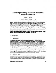
Fig. 1. Diagram for a scattering object showing an object-conformable mesh termination boundary.
where is the wave number. Equation (1) is subject to Dirichlet or Neumann (or both) boundary conditions on the surface of the scattering object. Consider the scattering object shown in Fig. 1. Using FEM, we mesh the region bounded by the PEC scatterer and the object-conformable outer boundary, as shown in Fig. 1. The th order BT operator specified at a circular boundary with is given by origin at
The implementation of (6) requires that the outermost boundary nodes that are involved in the definition of (5) lie on mutually orthogonal curves (as shown in Fig. 1). For instance, , five nodes lying on the normal to the when using BT outer boundary are needed. Let us denote the boundary nodes that lie on the outermost , the nodes that are adjacent to the boundary surface as outermost surface and are involved in the description of as , and the remaining nodes as . Enforcing (6) at each boundary node, we arrive at the algebraic boundary equation (7) The finite elements or finite-difference matrix can be symbolically represented as
(2) We enforce (2) on the outer boundary at each node using the osculating circle approximation. This requires determining the curvature of the osculating circle at each node (the node and two adjacent ones are sufficient to determine the curvature). Effectively, we can represent the ABC at each node as (3) represents the curvature of the osculating circle at outer boundary nodes. For the special case of zero curvature, as in the case of planar terminal boundaries, (3) reduces to (4) When the outer boundary is planar and coinciding with the Cartesian planes, (4) reduces to Higdon’s boundary condition when it is applied in the frequency domain (after the to ) [11]. transformation of III. IMPLEMENTATION IN FINITE-ELEMENTS AND FINITE-DIFFERENCE SIMULATIONS Here, we will present a simple procedure that implements the series of boundary conditions constructed above in an exact fashion. To this end, the operator in (3) is discretized using the following finite-difference approximation for the normal derivative (5)
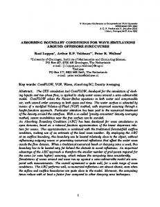
(8) Finally, we substitute (7) in (8) to obtain the reduced system matrix (9) This procedure is simple and, furthermore, for finiteelements simulation, it has the added advantage of eliminating the need to numerically evaluate the surface (boundary) integral that is inherent in finite-elements formulation. IV. NUMERICAL EXPERIMENT Testing ABC’s can never be an absolute procedure; that is, it is difficult to construct a numerical experiment that can test the effectiveness of ABC’s in a uniform fashion. This is the case because the field generated or scattered by an object can have , etc.), and the a variety of waves (traveling, evanescent, relative magnitude of these waves can also differ depending on the shape, size, and composition of the object (see [12] for a discussion on the testing of ABC’s). Therefore, while a single example will not suffice, here we present several numerical experiments that include objects of varying shapes and sizes with the goal of providing a good feel of the behavior of the ABC’s proposed. Let us consider the problem of 2-D plane wave scattering from the perfectly conducting cylinder shown in Fig. 2. This object is composed of a rectangle with two semicircles, one at each end. TM-polarization is considered with two different angles of incidence (0 and 90 ). The mesh-terminating boundary is taken to conform to the structure. The spacing is . The outer boundary is taken between node layers,
RAMAHI: ABSORBING BOUNDARY CONDITIONS FOR CONVEX OBJECT-CONFORMABLE BOUNDARIES
Fig. 2. Scattering object used in the first numerical experiment.
1143
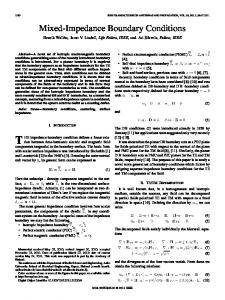
Fig. 4. Scattered electric field along 0 in Fig. 2 as obtained for 90� incidence, TM-polarization, using the MoM solution and the FEM solution using BT2local (BT2) and BT4local (BT4).
Fig. 3. Scattered electric field along 0 in Fig. 2 as obtained for 0� incidence, TM-polarization, using the MoM solution and the FEM solution using BT2local (BT2) and BT4local (BT4).
to be as conformable as possible with uniform separation from the conductor of . In Figs. 3 and 4 we present results showing the scattered electric field at the contour (see Fig. 2) for two separations; and . A total of 240 nodes span the contour, starting at the upper right-hand corner as shown in Fig. 2. Comparison is made with the FEM solutions employing and BT and the method of moments (MoM) BT results solution. The first observation we make is that BT in a very satisfactory agreement with the MoM solution. This agreement is especially satisfactory for the case of 90 incidence which is more challenging since scattered waves are generated on the conductor’s top and bottom surfaces that engage the outer boundary at angles of incidence close to grazing incidence. The second observation concerns the and BT . We notice from relative convergence of BT Fig. 4 that the convergence of the solution using BT as the distance from the outer boundary to the conductor . increases is much slower than the case when using BT This observation confirms earlier results which showed that the operators need to be enforced at a relatively BT and BT
Fig. 5. Computational domain used for the problem of scattering by a perfectly conducting square cylinder.
large distance from the conductor to obtain practical levels of accuracy (see [3] as an example). As a second experiment, we consider the problem of scatterperfectly conducting square cylinder. ing by a The most suitable outer boundary for this geometry is a square as shown in Fig. 5. The outer boundary is positioned such . The that the separation between it and the conductor is spacing between node layers is as before. Fig. 6(a) and (b) shows the magnitude and phase of the (see Fig. 5) as electric field on the observation contour calculated using the FEM solution. A total of 164 nodes span the observation contour. The numbering of the nodes starts at the lower left-hand corner and proceeds clockwise. So node number 20 corresponds to the middle point on the left-hand side, and node number 105 corresponds to the middle point on the right-hand side. Results are only shown for field values on the upper half of the contour due to the symmetry of the problem. For comparison, the MoM solution is also provided
1144
IEEE TRANSACTIONS ON ANTENNAS AND PROPAGATION, VOL. 47, NO. 7, JULY 1999
(a)
Fig. 7. Geometry for perfectly conducting ellipse and outer boundaries.
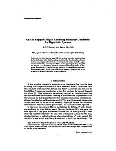
(b) Fig. 6. Scattered electric field, TE-polarization, along 0 in Fig. 5 obtained using the MoM solution, and the FEM solution using BT2local (BT2) and BT4local (BT4). (a) Magnitude. (b) Phase.
for this problem. The FEM solutions were obtained using and BT . The agreement between BT and MoM BT solutions is very satisfactory, especially in the observation region closest to the corner of the conducting box. In fact, it is observed from Fig. 6(a) that the maximum error in the field magnitude is kept below 1.2% over the entire observation is used. (Notice that the conducting box contour when BT was modeled as having precisely 90 corners.) As a third and final example, we consider the problem of TE-polarization scattering from a perfectly conducting ellipse and a minor axis of (axial ratio having a major axis of of 0.1). An object-conformable boundary was constructed, as shown in Fig. 7, such that the separation between the . For this problem, we conductor and outer boundary is on the outer obtain the FEM solution while employing BT boundary . We also obtain the solution while enforcing the classical second-order BT operator, BT , at a circular outer from the nearest conductor boundary, which is distanced surface, as shown in Fig. 7. The solutions, in terms of the radar cross section (RCS), are shown in Fig. 8. In Fig. 8, “BT4-
Fig. 8. RCS for the problem of TE-polarization scattering from the ellipse shown in Fig. 7.
small” refers to the solution obtained while using BT over the contour and “BT2-large” refers to the solution obtained while using BT over the larger circular contour. The agreement between the two solutions is very strong, thus . testifying to the strength and efficiency of BT V. CONCLUSION This paper presented the development of a new class of ABC’s that can be applied on noncircular convex meshtermination boundaries. The new ABC’s are based on the exact application of BT operators using local scattering centers. Also presented, the implementation of these ABC’s in a finiteelements and finite-difference simulation methods. Several representative examples were given, which showed that the new ABC’s give very satisfactory solutions. Finally, we note that this work demonstrated the application to scattering problems in 2-D space and in the frequency domain. However, these ABC’s and their implementation are directly applicable to scattering problems in three-dimensional
RAMAHI: ABSORBING BOUNDARY CONDITIONS FOR CONVEX OBJECT-CONFORMABLE BOUNDARIES
space and to time-domain problems. These extensions are discussed in greater detail in future works. ACKNOWLEDGMENT The author would like to thank A. Peterson for providing the MoM code that was used for comparison in this work. REFERENCES [1] A. Khebir, O. Ramahi, and R. Mittra, “An efficient partial differential equation technique for solving the problem of scattering by objects of arbitrary shape,” Microwave Opt. Technol. Lett., vol. 2, no. 7, pp. 229–233, July 1989. [2] O. M. Ramahi, A. Khebir, and R. Mittra, “Numerically derived absorbing boundary condition for the solution of open region scattering problems,” IEEE Trans. Antennas Propagat., vol. 39, pp. 350–353, Mar. 1991. [3] B. Lichtenberg, K. J. Webb, D. B. Meade, and A. Peterson, “Comparison of two-dimensional conformal local radiation boundary conditions,” J. Electromagn., vol. 16, no. 4, pp. 359–384, July/Aug. 1996. [4] G. A. Kriegsmann, A. Taflove, and K. R. Umashankar, “A new formulation of electromagnetic wave scattering using an on-surface radiation boundary condition approach,” IEEE Trans. Antennas Propagat., vol. 35, pp. 153–161, Feb. 1987. [5] Y.-C. Ma, “A note on the radiation boundary condition for the Helmholtz equation,” IEEE Trans. Antennas Propagat., vol. 39, pp. 1526–1530, Oct. 1991. [6] J.-M. Jin, The Finite Element Method in Electromagnetics. New York: Wiley, 1993. [7] O. M. Ramahi, “Exact implementation of higher-order Bayliss–Turkel absorbing boundary operators in finite-element simulation,” IEEE Microwave Guided Wave Lett., vol. 8, pp. 360–362, Nov. 1998.
1145
[8] T. B. A. Senior, J. L. Volakis, and S. R. Legault, “Higher order impedance and absorbing boundary conditions,” IEEE Trans. Antennas Propagat., vol. 45, pp. 107–114, Jan. 1997. [9] M. Kuzuoglu and R. Mittra, “Investigation of nonplanar perfectly matched absorbers for finite-element mesh truncation,” IEEE Trans. Antennas Propagat., vol. 45, pp. 474–486, Mar. 1997. [10] F. L. Teixeira and W. C. Chew, “Conformal perfectly matched layer,” in Proc. 14th Annu. Rev. Progress Appl. Computat. Electromagn., Monterey, CA, Mar. 1998, pp. 500–501. [11] R. L. Higdon, “Absorbing boundary conditions for acoustic and elastic waves in stratified media,” J. Comp. Phys., vol. 101, pp. 386–418, 1992. [12] O. M. Ramahi, “ABC’s: From theory to practice,” Appl. Computat. Electromagn. Soc. Newslett., vol. 11, no. 1, pp. 20–26, Mar. 1996.
Omar M. Ramahi (S’86–M’90) received the Ph.D. degree in electrical and computer engineering from the University of Illinois at Urbana-Champaign in 1990. From 1990 to 1993, he was a Postdoctoral Research Fellow at the University of Illinois at UrbanaChampaign. From 1993 to 1998 he was with Digital Equipment Corporation, Maynard, MA. Currently, he is part of the Alpha Servers Development Group at Compaq Computer Corporation. He is the coauthor of EMI/EMC Computational Modeling Handbook (Norwell, MA: Kluwer, 1998). He has published more than 80 conference and journal papers. His interests include applied and computational physics, radiation phenomenon, wide-band antennas, high-speed digital circuits, and packaging and medical applications of electromagnetics.