May 3, 1995 - of the dispersion equation which vanish when the dimension of the line ... dimensions : w = 0.63 mm, 5 = 9.7, h = 0.635 mm. - Extraction of the ...
IEEE TRANSACTIONS ON MAGNETICS, VOL. 31, NO. 3. MAY 1995
1637
EDGE BOUNDARY CONDITIONS DERIVED FROM SPECIFIC MODES OF MICROSTRIP LINE IN PLANAR CIRCUITS TWO-DIMENSIONAL ANALYSIS. S. ARIGUEL*, A. G O M E S NETO***, D. BAJON*, H. BAUDRAND** *ENSAE, 10 Avenue E. BELIN, BP 4032,3 1055 TOULOUSE. ** laboratoire microondes ENSEEIHT, 2 Rue CAMICHEL, 31071 TOULOUSE. *** DEE CCT UFPB Campina Grande, PB. Brasil. Abstract : The Nlwave analysis of the specific modes of microstrip lines is shown to provide an edge boundary condition for the two-dimensional analysis of planar circuits. This edge line boundary condition accounts for the dispersive behavior of the fringe fields all around the original open structure and relates the normal derivative of the electric field to the tangential one. Applied to a microstrip line, this edge line boundary condition gives an approximated dispersion equation consistent with the fullwave one. The first step will be to discuss specific modes in fullwave analysis in the spectral domain. The second step substitutes the edge line boundary condition for the usual Neuman's boundary condition in the integral Green's equation applied to planar discontinuities. Application to a symmetrical patch shows computed results that concord with experimental data in the whole frequency range.
I- INTRODUCTION The dispersive behavior of planar circuits must be analysed in order to account for the fringe fields around them. This has been done with fidlwave analysis. However, fidlwave analysis is often achieved in the spectral domain which requires a boxed structure. Thus analysis in the spectral domain, when applied to a microstrip line, produces solutions for the dispersion equation which are not directly related to the line itself. Some of these solutions are related to the enclosure or the dielectric slab. Hence, s@ic modes of boxed or shielded planar lines are defined as the solutions of the dispersion equation which vanish when the dimension of the line tends to zero. Consistent edge boundary conditions used in a hvodimensional analysis might allow reliable prediction of the cut-off wavenumbers of a transmission line. In other words, two-dimensional dispersion equations must have roots closely related to the specific modes obtained with a threedimensional analysis. The edge line boundary condtions is obtained by assuming a quasi-TEM propagation for the fringe fields and determined from the knowledge of two specific modes. Since the edge line boundary conditions are only dependent on the physical dimensions and relative permittivity of the used substrate, they are applied to twodimensional anlysis of planar Qscontinuities.
IT- FULLWAVE CALCULATION OF SPECIFIC MODES.
Fullwave analysis in the spectral domain replaces the original open structure by a shielded or boxed structure. This analysis takes advantage of available &mete expansion of the fields. In this paper, our approach was to avoid any disturbance of the fringe field and to reduce the occurence of boxed modes. The lateral box was removed and the semiinfinite shielded structure, shown in Fig. 1 was analysed with the extended transverse resonance technique (ETRT). ETRT uses transverse resonance technique [l-21 in the direction where the structure is infinite and analyses the structure in Fig. 1 as a bifurcation. Usual transverse resonance technique expands the fields in each homogeneous parts of cross section of the structure and states the resonance condition. ETRT constitutes a generalization of this approach since the fields in the infinite inhomogeneous have space on the edge the metallic strip are expanded on the hybrid modes of the corresponding partially filled waveguide. The resonance condition is written on the side wall if the microstrip line Fig. 1.
-
I
I I I
b
l
'b
-
Ih n h n u t y plane a ' (a) (b) Fig. 1 : cross section of the semi-infinite shielded structureand equivalent network representation for the formulation. symdnc plane
The overall formulation process is summarized in Fig. 1 by the equivlent network representation of the cross section. In the equivalent network , the adjustable voltage sources represent the fields on the discontinyityplane expanded for the solution [3]. The immittance va,Yb and Yc are the generalized admittance operators associated with the homogpxws region on upper and the lower side of the strip while Yc is associated with the lateral inhomogeneous half unbounded space. The resonance condition imposes [l-31
0018-9464/95$04.00 0 1995 IEEE
that the currents in the virtual adjustable sources on the discontinuity plane are zero.
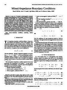
modes 14 : specific modes
modes 3-5 : housing modes
The moment method procedure applied to (1) gives an algebraic set of homogeneous equations. The cancelling condllion for the determinant provides the dispersion equation for the structure : (2)
det(Y(y)) = O
The attenuation constants of the higher order modes and the wavenumbers of the propagative hybrid modes are found in the frequency range of practical interest as the real or imaginary values of y. mode 1
10
F (GHz)
Fig. 2 : Dispersion curves for a shielded microstrip line with dimensions : w = 0.63 mm, 5 = 9.7, h = 0.635 mm.
- Extraction of the specijc modes. Some of the solutions shown in Fig. 2 are not directly related to the presence of the strip. Since spectfic modes by definition are modes whose existence is directly related to the presence of the metallic strip, a sensitivity analysis of these solutions against the geometrical parameters of the structure as, the width of the strip, the position of the top shield and the relative permittivity allows to determine which of them are specific modes. In Fig. 2, two zero cut-off modes are reported. In a shielded structure as shown in Fig 1, two dominant specific modes have to be anticipated since the top shield adds another unexpected microstrip line to the original microstrip line under study. This unexpected microstrip line has a ground plane due to the top metallic plane. In the set of equation (2) solutions, shown in Fig. 2, the sensitivity analysis reveals the following correspondances between the modes and the elementary structures which make up the studed cross section in Fig 1 :
mode 2 : Specific mode of the top line
-
III-TWO-DIMENSIONAL ANALYSIS Less computational effort can be done if the open original three-dimensional problem is reduced to a two-dimensional homogeneous problem with appropriate boundary condition. This can be accomplished if the appropriate boundaq condition takes into a m u n t the electromagnetic fields in the surrounding open space. In standard two-dimensional analysis, the equivalent waveguide model [2][4], states that the domain is bounded with magnetic walls. This is based on the assumption that all the electromagnetic energy is concentrated in the dielectric. In this context, the spread of the fields around the circuit is accounted for through a slight widening of the exqension of the circuit and the definition of a frequency dependent for the effective permittivity (Fig. 3-a). The alternative approach investigated here consists in defining appropriate "edge" boundary conditions that accounts for all the surrounding space. Substituting the magnetic wall boundary condition with this boundary condition preserves the actual geometrical dimensions and the permittivity. The open domain arround the printed circuit results in surrounding fringe fields. When a quasi-TEM propagation is assumed for the fringe fields, the "edge" boundary conditions become the "edge line" boundary conditions as illustrated in Fig. 3-b. A first step is to apply t h s boundary condition to a microstrip line. T h s boundary condition has to provide a dispersion equation consistent with the specific modes derived from the fullwave analysis.
- Edge line boundary conditions On each side of the microstrip line, the fringe fields are assumed to be responsible for a quasi-TEM like energy flow. The physical line can be consideded to be decomposed in three lines : the main line and two fictitious lines called the "edge lines". These edge lines are associated with the propagation of the fringe fields. Two frequency dependent parameters are sufficient to characterize these edge lines and define the frequency dependent elementary LC-cell.
I639
Fig. 3 : Microstrip line models : (a) - Magnetic wall model (b) - Edge 1ipe model
In the main line, the electric field E verifies the Helmholtz equation :
(3)
The existence of fringe fields implies that normal derivative of E is non zero and acts as a current density which feeds the edge lines on each lateral sides of the domain. Thus the expressions are :
Setting C O = s o p o / L , the variation of the two edge parameters against frequency is given in Fig. 4. The abrupt variation of the edge capacitances around 9 Ghz represents the effect of the energy transfer from the fundamental mode to the first higher order mode which becomes propagative and has the same even q-mmetry. The first two even modes used for the determination of the edge capacitances are plotted in Fig 5. To show the influence of the boundary conditions towards the solutions of the dispersion equation, these modes are compared to the same modes given with magnetic wall boundary conditions applied to the actual structure. Great discrepancy is observed in particular, in the low frequency range. In order to validate the edge line model, the prediction obtained in ( 5 ) for the third higher order made, with odd symmetry, is compared in Fig. 6 with the corresponding specific mode obtained in (2). The two solutions are shown to be closely related, in particular around the cut-off domain. Two models predict the same cut-off frequency and the frequency behaviour of the two dispersion curves that are closely related while discrepancy is observed with the magnetic wall model.
120
(4)
E
where d / &I denotes the normal derivative and 8 / atz the second tangential derivative along the line. Inside the dielectric domain bounded by the two edge lines, the formal solutions of the Helmholtz equation (3) have a cosine or a sine form in which the k, wavenumber is given byk:=Jk:-y*. Due to the invariance of the structure in the propagation duedon, the tangential derivative at2 in (4) is equivalent to 7 * in that case. The substitution of the solution of (3) in (4) provides the dispersion equation on the microstrip line in the edge line model as : r
-.
z =1w --
3 B Y
MI60
--
n
Fig4 : Edge parameters for a microstrip line with dimensions as: w = 0.635 mm, h = 0.635 mm, E~ = 9.7. 10
-+
1-10
(5)
where F stands for tan or cotan functions according to even or odd modes are studied. F (GHz)
-Identification of the edge line
The two parameters LC in (5) have to be found in order to obtain the two-dimensional equation that has the same roots as (2). However, only the specific modes can be retained from the lllwave analysis and used in ( 5 ) to obtain the LCcell against the frequency.
Fig5 : Dispersion curve for the dominant mode and the 1st higher mode (magnetic symmeq) : -edge line model and fullwave analysis, - - - magnetic wall boundary condition applied on. the actual structure
I MO
a
- ,+ t--f--
+
- t+----+-+
F IWr)
Fig.6 : Dispersion curve for the 1st higher mode (electrical bqmnetry : - edge line model, - - - fillwave analysis, magnetic wall boundary condition applied on the a c h d stnicture.
IV-APPLICATION TO .DISCONTINUITIES The two-dimensional analysis of planar circuits is based on the Green equation applied to the electric field on the contour of the circuit. The numerical procedure is done by using the boundary clement method [ 5 ] . The boundary element method provides versatility for this approach since it allows the analysis of completely arbitrary shaped planar circuits. Nevertheless the Neuman's condition used in the Green equation limits the accuracy of the description of the dispersive behaviour on the wide frequency range, in particular around the absorption frequency at whch the first higher order mode reaches cutOff.
Since edge lines boundary conhtions insure an effective prediction of microstrip lines cut-off frequencies while being only dependent on the actual dimensions and relative permittivity of the used substrate, they are now introduced in the Green equation in place of Neuman's condition. Moreover as seen in equation (4), the edge lines boundary conhtion include a differential operator which relates the m a l derivative of the electric field to its tangential derivative along the edges of the printed element. The substitution of (4)in Green's equation gives :
in which ' denotes the part of r outside the access ports. The adrmttance matrix of the generalized multiport is obtained using the multimodal expansion of the fields in the port [5] derived from the approximate dispersion equation (5). - Exemple :
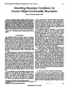
In Fig. 7, the computed reflection coefficient of a symmetrical patch is in accordance with the experimental results.
F loml
Fig.7 : Reflection coefficient ofa symmetricalpatch.
V- CONCLUSION Edge line boundary conditions are defined to introduce the frequency behaviour of fringe fields in two-dimensional planar circuit model. To define this edge line boundary, cutoff wavenumbers of shielded microstrip line were investigated and the concept of spectfic mode appeared to be the key point for the definition of edge line boundary condition. Edge line boundary conditions provide a dispersion equation of microstrip lines consistent with that obtained with a fullwave analysis. Only two parameters are need for each frequency to define the edge line boundary conditions. Their boundary conditions are only related to the actual geometry of the line. Boundary conditions are introduced in the Green's equation in place of the Neuman's condition in the planar circuit model. The description of the frequency behaviour of a discontinuity on the whole frequency range is demonstrated. The actual geometry of the circuit can be conserved. Computed results are closed to the measured results. Due to the versatility of the boundary element m e t h d application to more complex can be undertaken and a data base for edge lines may be built from a quite versatile simulation tool.
VI- REFERENCES [I] T. ITOH, Numerical Technics for Microwave and Millimeter Passisve structures, Wiley, 1989. [2] R. Sorrentino, 'Plunar circuits, waveguide models and segmentation method, " IEEE Trans.h4icrowuve Theory Tech., voL M7T-33, ~~10.57-1066, Oct. 1985. [3] H. Aubert, B. Souny and H. Baudrand, "Origin and advoidance of spurious solutions in the transverse resonance method," EEE Tmns.Microwave Theory Tech., vol. M T - 4 1 , pp4.50-456, March 1990.
1641
[4]T. Okoshi and T. Miyoshi, "lhc planar circuit - An approach to microwave integrated circuitry," IEEE Trans. Microwave Theory Tech., vol. MTT-20,pp245-252, April 1972. [ 5 ] M. Koshiba, M. Suzuky, "Application of bundary-element method to waveguid discontinuities," IEEE T m s . Microwave Theory Tech., vol. MTT-34,pp301-307, Feb. 1986.