respectively. The particle experiences elastic collisions with the scatterers and .... Thus, we only consider the propagator given by the reflected path. r a Ï Ï Î· ...... de Broglie wavelength λ = 10â7 moves back and forth between two disks of radii a = 1, with .... Eqs. (3.14, 3.15) hold for systems with hard wall poten- tials in any ...
ABSTRACT Title of Dissertation:
Dynamics of wave packets in the quantum Lorentz gas Arseni Goussev, Doctor of Philosophy, 2005
Dissertation directed by: Prof. J. Robert Dorfman Department of Physics This dissertation addresses the dynamics of a quantum particle moving in an array of fixed scatterers. The system is known as the Lorentz gas. The scatterers are taken to be two- or three-dimensional hard-spheres. The quantum Lorentz gas is analyzed in two dynamical regimes: (i) semiclassical regime, and (ii) high-energy diffraction regime. In both regimes the dynamics of the quantum particle is found to be determined by properties characterizing chaotic dynamics of the counterpart classical Lorentz gas. Thus, this dissertation provides an attempt to more deeply understand the role that classical chaos plays in quantum mechanics of nonintegrable systems. In the semiclassical regime, the quantum particle is represented by a small Gaussian wave packet immersed in the array of scatterers. The de Broglie wavelength of the particle is considered to be much smaller than both the scatterer size and the typical separation between scatterers. It is found that for times, during which the wave packet size remains smaller than the scatterer size, the spreading of the quantum wave packet is exponential in time, and the spreading rate is determined by the sum of positive Lyapunov exponents of the corresponding classical system.
The high-energy diffraction approximation allows one to analytically describe the dynamics of large wave packets in dilute scattering systems for times far beyond the Ehrenfest time. The latter is defined as the time during which the evolution of the wave packet is predominantly classical-like. The following two conditions are satisfied by the system in the high-energy diffraction regime: (i) the ratio of the particle’s de Broglie wavelength to the scatterer size is much smaller than unity, and (ii) this ratio is much larger than the ratio of the scatterer size to the typical separation between scatterers. The time-dependent autocorrelation function is calculated for wave packets in hard-disk and hard-sphere geometrically open billiard systems. The envelope of the autocorrelation function is shown to decay exponentially with time, with the decay rate determined by the mean Lyapunov exponents and the Kolmogorov-Sinai entropy of the counterpart classical system.
Dynamics of wave packets in the quantum Lorentz gas by Arseni Goussev
Dissertation submitted to the Faculty of the Graduate School of the University of Maryland, College Park in partial fulfillment of the requirements for the degree of Doctor of Philosophy 2005
Advisory Committee: Prof. Prof. Prof. Prof. Prof.
J. Robert Dorfman, Chairman/Advisor Stephen J. Wallace Adil B. Hassam Daniel P. Lathrop Michael A. Coplan
c Copyright by ° Arseni Goussev 2005
DEDICATION
To my uncle and my first teacher Sergey Petrovich Berlov
ii
ACKNOWLEDGMENTS I am truly grateful to my advisor and teacher Prof. J. Robert Dorfman for all his invaluable help, guidance, support and encouragement during the years of my graduate studies at the University of Maryland. It is my luck and great honor to have worked with and learned from such an exceptional scientist and a wonderful human being as Bob. A special thanks goes to my friend and colleague Ilya Arakelyan for his help, advice and optimism. The first part of this dissertation greatly benefited from a close collaboration with Daniel W´ojcik who I am deeply thankful to. I would like to acknowledge Viatcheslav Merkine, Aleksandr Ukhorskiy, Matthew Reames and Luis Nasser for numerous helpful conversations. I would also like to thank the members of my dissertation committee for their useful comments and suggestions. I am grateful to the Department of Physics in general and to Prof. Nicholas Chant in particular for making my years in the graduate school a pleasant and enjoyable experience. I would like to express my gratitude to all my friends and family for their unconditional support and patience throughout these years.
iii
TABLE OF CONTENTS
List of Tables
vi
List of Figures
vii
1 Introduction
1
1.1
Integrability and chaos . . . . . . . . . . . . . . . . . . . . . . . . .
1
1.2
Classical mixing and quantum revivals . . . . . . . . . . . . . . . .
4
1.3
Overview of dissertation . . . . . . . . . . . . . . . . . . . . . . . .
8
2 Short-time semiclassical Lorentz gas 2.1
2.2
2.3
10
The Lorentz gas model . . . . . . . . . . . . . . . . . . . . . . . . .
10
2.1.1
Classical Lorentz gas . . . . . . . . . . . . . . . . . . . . . .
11
2.1.2
Lorentz gas in the semiclassical regime . . . . . . . . . . . .
12
Wave packet propagation in two dimensions . . . . . . . . . . . . .
13
2.2.1
Construction of the propagator . . . . . . . . . . . . . . . .
13
2.2.2
Spreading of the wave packet . . . . . . . . . . . . . . . . .
22
2.2.3
Lyapunov regime . . . . . . . . . . . . . . . . . . . . . . . .
25
Propagator in three dimensions . . . . . . . . . . . . . . . . . . . .
29
3 Periodic orbit revivals and the Loschmidt echo
34
3.1
The wave packet autocorrelation function . . . . . . . . . . . . . . .
34
3.2
Mass perturbation Loschmidt echo . . . . . . . . . . . . . . . . . .
40
4 The Lorentz gas in high-energy diffraction regime 4.1
Energy-dependent propagator for the Lorentz gas . . . . . . . . . .
iv
45 45
4.2
Autocorrelation function in the energy domain . . . . . . . . . . . .
50
4.3
Time-domain autocorrelation function . . . . . . . . . . . . . . . .
53
4.3.1
Two-disk billiard . . . . . . . . . . . . . . . . . . . . . . . .
54
4.3.2
Three-disk “equilateral” billiard . . . . . . . . . . . . . . . .
59
4.3.3
Three-disk “isosceles” billiard . . . . . . . . . . . . . . . . .
65
5 Simple theory for the autocorrelation function decay
72
5.1
Formulation of the method . . . . . . . . . . . . . . . . . . . . . . .
72
5.2
Application to studied cases . . . . . . . . . . . . . . . . . . . . . .
74
5.2.1
Three-disk “equilateral” billiard . . . . . . . . . . . . . . . .
75
5.2.2
Ruelle pressure function . . . . . . . . . . . . . . . . . . . .
78
5.2.3
Three-disk “isosceles” billiard . . . . . . . . . . . . . . . . .
81
New hard-disk scattering systems . . . . . . . . . . . . . . . . . . .
87
5.3.1
Generic three-disk billiard . . . . . . . . . . . . . . . . . . .
87
5.3.2
Scattering systems in three spatial dimensions . . . . . . . .
90
5.3
6 Conclusions and future directions 6.1
6.2
97
Summary of the main results of the dissertation . . . . . . . . . . .
97
6.1.1
Short-time semiclassical regime . . . . . . . . . . . . . . . .
97
6.1.2
High-energy diffraction regime . . . . . . . . . . . . . . . . .
99
Future directions of research . . . . . . . . . . . . . . . . . . . . . . 100
A Lyapunov exponents for disk and sphere billiards
104
A.1 Two-disk Lyapunov exponent . . . . . . . . . . . . . . . . . . . . . 104 A.2 Three-disk Lyapunov exponents . . . . . . . . . . . . . . . . . . . . 107 A.3 Lyapunov exponents in three-dimensional systems . . . . . . . . . . 109 B Hard-disk binary collision operator
112
C Free streaming autocorrelation function for Gaussian wave packets
115
v
LIST OF TABLES 5.1
Long mean free path trajectories for the case of the “isosceles” threedisk billiard. . . . . . . . . . . . . . . . . . . . . . . . . . . . . . . .
5.2
83
Autocorrelation function decay exponents for three-disk billiards of different symmetries, and with α ≈ β ≈ 1. . . . . . . . . . . . . . .
vi
90
LIST OF FIGURES 1.1
Three phase space trajectories of the driven anharmonic oscillator defined by Eq. (1.1). The two solid lines represent the regular tori, while the cloud of points corresponds to the chaotic sea. The figure is taken form reference [5]. . . . . . . . . . . . . . . . . . . . . . . .
1.2
3
Energy eigenvalues of Sinai quantum billiard as function of the disk radius. The dashed line indicates the limit of applicability of the perturbation theory. The picture is taken from reference [8]. . . . .
1.3
5
The probability density of an energy eigenfunction for a quantum particle in the Bunimovich stadium. The figure is taken from reference [38]. . . . . . . . . . . . . . . . . . . . . . . . . . . . . . . . . .
2.1
7
Illustration of the Lorentz gas model in two dimensions. Two initially infinitesimally close trajectories are represented by solid and dashed lines. The separation δ between these trajectories is shown for some particular instant of time. . . . . . . . . . . . . . . . . . .
11
2.2
Particle-fixed frame of reference at time t = 0. . . . . . . . . . . . .
14
2.3
Particle-fixed frames of reference: (ζ 0 , η 0 ) at time 0 and (ζ, η) at t. .
15
2.4
The thin line represents the reflected trajectory starting from point r0 = (x0 , y 0 ) and leading to point r = (x, y). The point of particledisk collision is denoted by R = (X, Y ). The thick line corresponds
2.5
to the trajectory followed by the center of the wave packet. . . . . .
16
. . . . . . . . . . . . . . . . . . . . . . . . . . . . . . . . . . . . . .
19
vii
2.6
Free flight time evolution of ρ and σ: (a) classical case, ε = 0, (b) quantum case, ε > 0. . . . . . . . . . . . . . . . . . . . . . . . . . .
2.7
24
Wave packet size, σ, real radius of curvature, ρ, and ε, are shown as functions of time, t, for a two-disk periodic orbit. Disk radii a = 1, center-to-center separation R = 3, de Broglie wave length λ = 10−7 . The corresponding two-disk Lyapunov exponent λ/v ≈ 1.32. Initial wave packet size σ0 = 2 · 10−4 and ρ0 = 10. The particle is located in the middle between the two disks at t = 0. Exponential trends are shown for plots of σ and ε. All distances are measured in units of disk radius a. . . . . . . . . . . . . . . . . . . . . . . . . . . . . .
3.1
27
A Gaussian wave packet is shown at time t = 0 (centered about point O), and at a later time t = nT + ∆/v (centered about point P ). Points O and P lie on the same periodic orbit, and are separated in time by n (= 0, 1, 2, . . . , N ) periods, T , of the periodic orbit, plus a short time interval ∆/v. The separation distance ∆ is assumed to be sufficiently small in order for the initial and final wave packets to overlap significantly. . . . . . . . . . . . . . . . . . . . . . . . . .
3.2
36
Revival peaks of the wave packet auto-correlation function, C(t), for the same two-disk periodic orbit as in fig. 2.7: a = 1 and R = 3. Particles de Broglie wave length λ = 10−7 . The initial wave packet is characterized by σ0 = σk0 = 2 · 10−4 and ρ0 = ρk0 = 10. The exponential trend is indicated by a straight line. . . . . . . . . . . .
4.1
Schematic sketch of a particle collision sequence corresponding to the matrix element in Eq. (4.15). . . . . . . . . . . . . . . . . . . .
4.2
39
49
Two-disk billiard. The circular wave packet is initially located on the classically periodic orbit distance r1 away from disk “1”, and distance r2 away from disk “2”, with r1 + r2 = R. . . . . . . . . . .
viii
54
4.3
Absolute value squared of the scattering part of the autocorrelation function C(t) as a function of vt/R for the two-disk billiard. Parameters of the system are as follows: a = σ = 1, R = 104 , r1 = r2 = R/2 and λ = 10−2 . The straight line shows exponential decay with the rate given by the classical two-disk Lyapunov exponent λ(2) . The decay is shown for times t greater than the Ehrenfest time tE ≈ R/2v. . . . . . . . . . . . . . . . . . . . . . . . . . . . . .
4.4
59
Three-disk “isosceles” billiard. The circular wave packet is initially located distance r1 away from disk “1”, and distance r2 away from disk “2”, with r1 + r2 = R. Disk “3” is distance αR away from disks “1” and “2”. The “equilateral” billiard case corresponds to α = 1. .
4.5
60
The autocorrelation function C(t) as a function of vt/R for the three-disk “equilateral” billiard. Parameters of the system are the same as for the two-disk billiard system: a = σ = 1, R = 104 , r1 = r2 = R/2 and λ = 10−2 . The straight line shows exponential decay with the rate given by γ (3) . The decay is shown for times t greater than the Ehrenfest time tE ≈ R/2v. . . . . . . . . . . . . .
4.6
64
(a) First two bands of poles for the case of α = 5/2 and R/a = 104 ; (b) magnification of the first band; (c) magnification of the second band. Dots correspond to exact values of the poles, and crosses show the same poles approximately predicted by Eq. (4.54) together with Eq. (4.53). . . . . . . . . . . . . . . . . . . . . . . . . . . . . . . . .
4.7
68
The autocorrelation function as a function of time for the “isosceles” three-disk billiard with α = 3/2. Disks “1” and “2” are separated by distance R = 104 a. The wave packet of the de Broglie wavelength λ = 10−2 a is initially located as shown in fig. 4.4 with r1 = r2 = R/2. The dotted and the solid straight lines represent e−λ
(2) t
(3)
and e−γα
t
decays respectively. . . . . . . . . . . . . . . . . . . . . . . . . . . .
ix
69
4.8
The autocorrelation function as a function of time for the “isosceles” three-disk billiard with α = 5/2. Disks “1” and “2” are separated by distance R = 104 a. The wave packet of the de Broglie wavelength λ = 10−2 a is initially located as shown in fig. 4.4 with r1 = r2 = R/2. The dotted and the solid straight lines represent e−λ
(2) t
(3)
and e−γα
t
decays respectively. . . . . . . . . . . . . . . . . . . . . . . . . . . . 5.1
70
Peaks of the autocorrelation function for the “equilateral” three-disk billiard calculated in accordance with Eqs. (5.1), (5.3) and (5.4). The dashed line shows e−γ
(3) t
decay, with γ (3) given by Eq. (4.47).
The radii of the disks constituting the billiard equal a = 1, while the disk center-to-center separation is R = 104 . This figure is to be compared with fig. 4.5. . . . . . . . . . . . . . . . . . . . . . . . . . 5.2
76
Peaks of the autocorrelation function calculated in accordance with Eqs. (5.1), (5.3) and (5.4) for the “isosceles” three-disk billiard with (3)
α = 5/2. The dashed line shows e−γα
t
(3)
decay, with γα given by
Eq. (4.55), while the dotted lines show the trend of the e−λ
(2) t
decay,
with λ(2) defined by Eq. (4.38). The billiard is parametrized by a = 1 and R = 104 . This figure is to be compared with fig. 4.8. . . . . . . 5.3
A three-disk billiard of the most general type. For concreteness, disks “1” and “3” have the largest separation, β > 1, α. . . . . . . .
5.4
82
87
Peaks of the autocorrelation function for the three-disk billiard with √ α = 2, β = 2, a = 1 and R = 104 . The initial wave packet starts between disks “1” and “2” as shown in fig. 5.3. Solid line represents (2)
e−λβ
t
(2)
decay, with λβ calculated according to Eq. (5.43); dashed (2) t
line corresponds to e−λ 5.5
decay, with λ(2) given by Eq. (4.38). . . .
88
The pyramidal four-sphere billiard. The wave packet is initially placed between spheres “1” and “2”, with its average momentum directed toward the sphere “2”. . . . . . . . . . . . . . . . . . . . .
x
92
5.6
Peaks of the autocorrelation function for three scattering systems: two-sphere (circles), “equilateral” three-sphere (triangles) and “pyramidal” four-sphere (diamonds) billiards. The radii of the sphere scatterers are a = 1, and the sphere center-to-center separation is R = 104 . The autocorrelation function decay rates for these billiards are calculated according to Eqs. (5.46), (5.50) and (5.53), and presented in the figure by the dotted, dashed and solid lines respectively. . . . . . . . . . . . . . . . . . . . . . . . . . . . . . . . . . .
6.1
94
An example of self-intersecting classical periodic orbit with small opening angle ε, and its neighboring periodic orbit. The figure is taken from reference [44]. . . . . . . . . . . . . . . . . . . . . . . . . 101
A.1 The radii of curvature of an infinitesimal cone of classical trajectories. ρ+ 1 corresponds to the instant of time right after the trajectories + scatter of disk “1”; ρ− 2 and ρ2 correspond to the instants of time
right before and right after the collision with disk “2” respectively. . 104 A.2 Free streaming evolution of the trajectory cone. . . . . . . . . . . . 105
xi
Chapter 1 Introduction In this dissertation we address the dynamics of quantum wave packets in arrays of fixed hard-disk and hard-sphere scatterers in two different regimes: (i) the shorttime, semiclassical regime, and (ii) the long-time high-energy diffraction regime. The main result of this work can be summarized in the following statement: in both regimes the essential properties of the time evolution of wave packets are determined by properties characterizing chaotic dynamics of counterpart classical systems. We begin the dissertation with a brief overview of the field of quantum chaos, followed by the outline of the work presented in the subsequent chapters.
1.1 Integrability and chaos Only a few systems in quantum mechanics in spaces of more than one dimensions allow exact analytical solutions. A free particle, particles in harmonic, square well and δ-function potentials are most common examples of such systems. It is due to separability of the Schr¨odinger equations for these potentials that the exact solutions become possible. A systematic classification of potentials in two- and three-dimensional Euclidean space in which one-particle Schr¨odinger equations are separable was given by Eisenhart [1]. Apart from the δ-function potential, which does not have an immediate classical meaning, the above-mentioned quantum mechanical systems have integrable classical counterparts.
1
Integrability for a d-dimensional classical system implies the existence of d constants of motion, including the Hamiltonian, which restrict the dynamics of the system in 2d-dimensional phase space to the motion on a number of d-dimensional manifolds. These manifolds are d-dimensional tori [2], i.e. by construction of the angle-action variables (θj , Ij ), with j = 1, 2, . . . , d, one can map the phase space dynamics of the integrable system on the set of d first order differential equations, dθj (t)/dt = ωj with ωj = ωj (I1 , I2 , . . . , Id ). So, all phase space trajectories of a classical integrable systems with finite number of degrees of freedom are either periodic or quasi-periodic. The Schr¨odinger equation is usually separable for quantum systems with integrable classical analogs. The spectra of energy levels of a classically integrable system can be obtained with high accuracy by means of the Einstein-BrillouinKeller (EBR) quantization rule [3], which is the improved version of the well known Bohr’s quantization rule for periodic orbits. In reality most of commonly encountered classical dynamical systems are nonintegrable. This implies that the number of integrals of motion is smaller than the dimensionality of the system. Then, the tori, associated with the integrals of motion, correspond to regular and stable motions of the system, and are surrounded by a chaotic “sea” – regions in phase space where the system evolves in a very irregular, stochastic-like manner [4]. The trajectories, of the system, while in chaotic regions, explore more than d dimensions of the 2d-dimensional phase space over infinite times. In the most extreme ergodic case the regular tori are absent, and all motions of the system are chaotic. To illustrate the dynamics of a nonintegrable system, fig. 1.1 presents a stroboscopic view of three different trajectories for a one-dimensional (d = 1) classical system defined by the Hamiltonian [5] H(x, p) =
p2 + Ax4 − Bx2 + γx cos(ωt), 2m
(1.1)
with m = 1, A = 0.5, B = 10, γ = 10 and ω = 6.07. This Hamiltonian describes a
2
Figure 1.1: Three phase space trajectories of the driven anharmonic oscillator defined by Eq. (1.1). The two solid lines represent the regular tori, while the cloud of points corresponds to the chaotic sea. The figure is taken form reference [5]. particle of mass m moving in the externally driven anharmonic potential, for which A and B parametrize the time-independent part of the double-well potential, γ is the driving force, and ω stands for the driving frequency. The two solid curves in fig. 1.1 correspond to two periodic trajectories (regular tori) confined to the stable islands that are centered at (x ≈ −1.5, p = 0) and (x ≈ 4.15, p = 0). The cloud of points belong to the third trajectory, and represent the stochastic-like motion of the system (chaotic sea). The field of quantum chaos is essentially the search for eigenstates and eigenvalues of quantum systems with chaotic classical counterparts. Schr¨odinger equations for such systems are nonseparable. Citing Haake [6], “nonseparability is shared
3
by the wave problem and the classical Hamilton-Jacobi equation ensuing in the short-wave limit and may indeed be seen as the deepest characterization of chaos”. As first pointed out by Einstein, the EBR quantization rule is also no longer appropriate for determination of energy spectra, since the quantization rule requires the existence of dense stable periodic motions in the system, which are completely absent in the chaotic regime where the periodic orbits are unstable. A significant progress in characterization of energy spectra in quantum analogs of classically chaotic systems was achieved in semiclassical regime by discovery of Gutzwiller trace formulae [7]. The latter express the energy level density for a quantum system in the small de Broglie wavelength limit in terms of sums over unstable periodic orbits of the corresponding classical chaotic system. Unlike the energy level structure of integrable systems, the energy spectra of classically chaotic systems avoid degeneracies [8, 6], and exhibit what has come to be known as “level repulsion”. Figure 1.2 illustrates the phenomenon of level repulsion for the quantum Sinai billiard. The Sinai billiard consists of a particle moving freely in two dimensions inside an infinitely high square well potential with a hard-disk scatterer placed in the center of the well. The side of the square well is taken to be unity, and the disk radius R is allowed to vary in the range 0 < R ≤ 0.5. Figure 1.2 shows the first 30 energy levels as function of the disk radius R. One can see a complete absence of degeneracies, i.e. no two energy levels intersect as the system parameter changes.
1.2 Classical mixing and quantum revivals The Hamilton equations of motion for a generic classical system are first order nonlinear differential equations, which determine time evolution of a point in the phase space. Peres [9] discussed a clever way to formulate classical mechanics in the Hilbert space by introducing a Liouville “wave function” Φ(r, p, t), defined on the phase space, such that the Liouville phase space density is f = |Φ|2 . Here, r
4
Figure 1.2: Energy eigenvalues of Sinai quantum billiard as function of the disk radius. The dashed line indicates the limit of applicability of the perturbation theory. The picture is taken from reference [8]. and p are spatial and momentum coordinates of the classical system respectively, and t represents time. Then, the classical Liouville equation can be written in terms of the classical “wave function” as i
∂Φ = LΦ, ∂t
(1.2)
where
µ ¶ µ ¶ ∂Hcl ∂ ∂Hcl ∂ L= −i − −i (1.3) ∂p ∂r ∂r ∂p is the linear Hermitian Liouville operator, and Hcl stands for system’s classical Hamiltonian. Equation (1.2) is formally equivalent to the Schr¨odinger equation for a quantum wave function, i~
∂Ψ = HΨ, ∂t
5
(1.4)
with the quantum Hamiltonian H, and a quantum wave function Ψ = Ψ(r, t). It was first proven by Koopman [10] that the time evolution of classical Liouville “wave functions” is unitary, i.e. the following overlap is invariant in time: Z h i∗ ˜ p, t) Φ(r, p, t), drdp Φ(r, ˜ are classical “wave functions” satisfying Eq. (1.2), and asterik where Φ and Φ indicates complex conjugation. The main qualitative difference between classical and quantum dynamics comes from comparison of eigenvalue spectra of operators L and H for bounded systems. In the generic case of a nonlinear classical system, the spectrum of the Liouvillian is continuous, while the spectrum of the Hamiltonian for the quantum analog of this system is discrete. Thus, an initial quantum state can always be represented, up to an arbitrary accuracy, by a linear combination of finite number of Hamiltonian eigenstates, while it takes an infinite number of Liouvillian eigenstates to construct the corresponding classical density. The time dependent wave functions read Ψ(t) =
X
i
an e− ~ En t
(1.5)
dn bn e−iLn t
(1.6)
n
and
Z Φ(t) =
in quantum and classical cases respectively. Here En and Ln are the spectra of Hamiltonian and Liouvillian respectively, while an and bn are the expansion coefficient of corresponding initial states. The wave function Ψ(t), given by Eq. (1.5) is quasi-periodic, i.e. for any desired accuracy ε one can find a time Tε such that kΨ(Tε ) − Ψ(0)k < ε. In other words, the time evolution of bounded quantum systems has recurrences, also known as wave function revivals [15]. The quantum recurrence time is usually much shorter than the Poincare recurrence time in the corresponding classical system [9]. On the other hand, infinite number of eigenstates of L participating in Liouvillian time evolution allows the classical density |Φ|2 to become more and more
6
distorted in the course of time, and to expand over the phase space, getting close to every point on the allowed energy shell. The resulting behavior is called mixing [4]. It is important to mention that the phenomenon of mixing does not contradict the Poincare recurrence theorem, since the latter is formulated only for individual phase space trajectories and not for the Liouvillian densities.
Figure 1.3: The probability density of an energy eigenfunction for a quantum particle in the Bunimovich stadium. The figure is taken from reference [38]. Another manifestation of the drastic difference between evolutions of classical and quantum probability densities is the phenomenon of eigenfunction “scars” in quantum analogs of bounded chaotic systems [38, 39]. Figure 1.3 shows an energy eigenfunction for the system known as the Bunimovich stadium. In the Bunimovich billiard system a particle moves inside a two-dimensional hard-wall cavity bounded by two semicircles (left and right boundaries) and by two straightline segments (top and bottom boundaries), see fig. 1.3. The figure is taken from Heller’s article [38]. The eigenfunction in fig. 1.3 has most of its probability density concentrated along an unstable (8-shaped) periodic orbit of the counterpart classical system. This is an example of a general statement, that quantum eigenfunctions of bounded chaotic systems are scarred along unstable periodic orbits.
7
This scarring enhances the role that classical periodic orbits play in time evolution of quantum states initially given by a superposition of a number of scarred eigenstates. As a result, the dynamics of wave packets in bounded systems is periodic or quasi-periodic, and exhibits revivals of the initial state. On the other hand, the time evolution of classical probability densities is not so simple, and usually results in mixing, as in the case of the Bunimovich stadium. The following quotation from Peres [9] neatly summarizes the comparison of quantum and classical dynamics in chaotic systems: “Quantum phenomena are more disciplined than classical ones”.
1.3 Overview of dissertation There are two common approaches to the quantitative description of quantum chaos. One is to explore the energy spectra in quantum analogs of classically chaotic bounded systems [6, 8, 44, 45, 46], and to study quantum scattering resonances in complex energy plane for geometrically open systems with chaotic classical repellors [21, 22, 23, 24, 25, 26]. The second approach focuses on the timedependent properties of quantum systems, such as the autocorrelation function [13, 15] and the Loschmidt echo [16, 17, 18]. The autocorrelation function gives the probability for the initial state of a quantum particle to recur after a certain time, and therefore characterizes the “quantum diffusion” of the initial state of a system. The Loschmidt echo, also known as fidelity, quantifies the sensitivity of quantum dynamics to perturbations of system’s Hamiltonian. The precise definitions for these quantities will be given in Chapter III. This dissertation mainly focuses on the time evolution and recurrence phenomena of quantum wave packets in the Lorentz gas model. The Lorentz gas consists of a particle, or a collection of non-interacting particles, traveling in an array of fixed scatterers, taken to be hard disks or hard spheres in two or three spatial di-
8
mensions respectively. The model represents a classically chaotic scattering system which has proven to be useful in classical theory of chaotic transport. Chapter II starts with the detailed description of the model in both classical and quantum cases. In this work we studied the wave packet dynamics analytically in two different regimes: (i) short time, semiclassical regime, and (ii) long time, high-energy diffraction regime. Chapter II discusses the evolution of small Gaussian wave packets in two- and three-dimensional semiclassical Lorentz gases for times shorter than the Ehrenfest time. Chapter III presents calculations of wave packet periodic orbit revivals, and of the Loschmidt echo of a special kind that characterizes the sensitivity of wave packet dynamics to small perturbations of the mass of the moving particle. All the results of Chapter III depend upon the short time wave packet dynamics, and are the applications of the general theory presented in Chapter II. To get beyond the short time semiclassical limit, we then consider the long time quantum dynamics of large wave packets for high energy particles. As a tool for our analysis we take the time-domain autocorrelation function for the wave packets. We study the time decay of the autocorrelation function in Chapters IV and V for large wave packets in dilute hard-disk and hard-sphere scattering systems and for times far beyond the Ehrenfest time. The results of these chapters hold for particles in Lorentz gases with a small number of scatterers. Calculations of Chapter IV utilize the technique of the multiple scattering theory, while the methods of Chapter V are based on simple physical arguments. Chapter VI presents the discussion of the main results of the dissertation and of the possibilities for future research.
9
Chapter 2 Short-time semiclassical Lorentz gas In this chapter we present a semiclassical calculation of the short time evolution of a wave packet in the quantum analog of a classically chaotic system, namely the Lorentz gas. We find that the semiclassical evolution has tight connections with the classical one, and analyze the transition to the classical dynamics in the limit of particle’s de Broglie wavelength going to zero. We also construct quantum analogs of finite time Lyapunov exponents characterizing the exponential separation of initially close trajectories of the classical system, and show, as one might expect, that they govern short-time spreading of small semiclassical wave packets.
2.1 The Lorentz gas model The Lorentz gas system consists of a particle traveling among a collection of fixed scatterers, taken to be hard disks or hard spheres in two or three dimensions respectively. The particle experiences elastic collisions with the scatterers and moves freely between the collision events. The number of scatterers may be infinite, and then the Lorentz gas has no boundaries, or may be finite, so that the scatterers compose a geometrically open billiard system. We will address the open hard-disk and hard-sphere billiards in Chapters IV and V. The scatterers may also constitute a regular array, or may be placed at random. The case where the scatterers are centered at the vertices of a regular lattice is the Sinai billiard. Related work on this problem has been done by Wirzba [25], and we will discuss it below.
10
2.1.1 Classical Lorentz gas
δ
Figure 2.1: Illustration of the Lorentz gas model in two dimensions. Two initially infinitesimally close trajectories are represented by solid and dashed lines. The separation δ between these trajectories is shown for some particular instant of time. The Lorentz gas model is a paradigm of the classical theory of chaotic transport. The model demonstrates exponential Lyapunov instability to small perturbations of the initial phase space location of the moving particle. As a result, trajectories that are initially close separate exponentially with time. Figure 2.1 shows the time evolution of two initially infinitesimally close trajectories in the two-dimensional Lorentz gas. The time dependence of the trajectory separation δ(t) is given by δ(t) ∼ eλt ,
(2.1)
where λ is the Lyapunov exponent corresponding to the particular pair of initially close trajectories. In the course of time, the separation between trajectories becomes greater than the scatterer size, and the trajectories start to collide with
11
different scatterers. For long enough times the collision sequences for the two trajectories become uncorrelated, and the separation growth is diffusive: δ(t) ∼
√
t.
(2.2)
The proportionality constant is determined by the diffusion coefficient of the Lorentz gas system.
2.1.2 Lorentz gas in the semiclassical regime Unlike classical mechanics, quantum mechanics can not be formulated in phase space, but is concerned with Hilbert space instead. The notion of phase space trajectories is no longer meaningful and one needs to deal with wave functions to describe time evolution of a quantum particle. A natural way to quantize the Lorentz gas is to represent the moving particle by an initially localized wave packet, and allow the wave packet to evolve in time according to the Schr¨odinger equation with properly chosen boundary conditions. To model the particle-scatterer elastic collision one needs to require the particle’s wave function to vanish at the scatterer surfaces. In other words the wave function has to satisfy the Dirichlet boundary conditions. In this chapter we consider the propagator for a semiclassical particle moving among the scatterers. The de Broglie wavelength of the moving particle is taken to be small compared both to the size of a scatterer and to the average distance between scatterers. The propagator is evaluated by semiclassical methods for time intervals where a number of collisions take place. We show that as long as the wave packet remains small, its spreading with time is governed by a set of equations that are the quantum counterparts to the curvature equations of Sinai and co-workers [12] that determine the Lyapunov exponents and Kolmogorov-Sinai (KS) entropy for the classical system. We can then easily relate the spreading of the wave packet to the classical Lyapunov exponents.
12
First we provide our calculations for two-dimensional systems with hard disk scatterers in two dimensions. The three-dimensional version of this work is presented in the last section of this chapter. There we show that the role of the positive Lyapunov exponent in our calculations for two dimensional systems is taken by the sum of the two positive Lyapunov exponents for the three dimensional system. According to Pesin’s theorem [14], this sum is equal to the Kolmogorov-Sinai entropy of the infinite Lorentz gas.
2.2 Wave packet propagation in two dimensions In this section we derive the semiclassical propagator for small quantum wave packets moving in the Lorentz gas.
2.2.1 Construction of the propagator We consider the semiclassical motion in two dimensions, d = 2, of a Gaussian wave packet, with average momentum p0 , whose initial form is given by µ ¶ i 1 ζ2 η2 hr|0i ≡ ψ0 (r) = p exp ζ− − , λ 4Ωk0 4Ω0 2πσk0 σ0
(2.3)
where λ = ~/|p0 | is the de Broglie wavelength of the moving particle, 2 σk0 =
1 µ
1 Re Ωk0
¶
σ02 =
and
1 µ ¶ 1 Re Ω0
(2.4)
characterize the size of the wave packet in the ζ- and η-directions respectively ( Re denotes the real part). The (ζ, η) system of coordinates is chosen with its origin at the center of the wave packet, r0 , and ζ-axis pointing in the direction of p0 , with η-axis perpendicular to p0 :
r = r0 + U0
13
ζ η
,
(2.5)
r
η
ζ
y p0 r0 x
Figure 2.2: Particle-fixed frame of reference at time t = 0. where U0 is a 2 × 2 real matrix relating the two coordinate systems, see fig. 2.2. When the wave packet is far from any scatterers, its time propagation is dominated by free streaming, described by the propagator Gfs (r, r0 , t) =
³ m ´d/2 im exp (r − r0 )2 , 2πi~t 2~t
(2.6)
where m is the mass of the moving particle, and d = 2. Application of this propagator to the wave function given by Eq. (2.3) yields, up to an irrelevant phase factor, a new Gaussian wave packet of the form of Eq. (2.3) with i Ωk0 → Ωkt = Ωk0 + λvt 2 i Ω0 → Ωt = Ω0 + λvt, 2
(2.7) (2.8)
where v = |p0 |/m is the average velocity of the particle. The new particle-fixed frame of reference is related to the stationary one by means of Eq. (2.5), with the wave packet center, r0 , replaced by rt = r0 + (p0 /|p0 |)vt and Ut = U0 . The average momentum of the wave packet stays unaffected: pt = p0 . Thus, the affect of the free streaming propagator on the Gaussian wave packet reduces to two linear transformation of wave packet parameters Ωk and Ω. To find the semiclassical propagator describing a collision of the particle with one hard-disk scatterer, we start with the general expression for the semiclassical
14
propagator as a sum of terms of the form [19] µ 0
Gsc (r, r , t) =
1 2πi~
¶d/2
µ ¶ p πµ S(r, r0 , t) |D| exp i +i , ~ 2
(2.9)
where S(r, r0 , t) is the classical action along a classical path from r0 to r in time t, µ is an index equal to twice the number of collisions of the particle with hard disk scatterers over time t [21], D = det(−∂ 2 S/∂r∂r0 ) is the Van Vleck determinant, and d = 2 is the dimensionality of the space. In general, there are two classical paths connecting points r and r0 , assuming that r is not in the geometric shadow of r0 : a reflected path and a direct one. The contribution of the direct path from r0 to r to the time evolution of the wave packet is negligible after time t if a classical particle with momentum p0 would collide with the scatterer during the interval (0, t). Thus, we only consider the propagator given by the reflected path.
ζ
η r0
φ
a
n
φ η’
ζ’ r0’
Figure 2.3: Particle-fixed frames of reference: (ζ 0 , η 0 ) at time 0 and (ζ, η) at t. Consider a wave packet centered around r00 at time t = 0 before a collision and around r0 at t after the collision, see fig. 2.3. The system of reference originates at the point of classical collision. We suppose that the wave packet to which the propagator will be applied is sufficiently small that we only need to find classical trajectories by minimizing the action for points starting close to r00 and ending close
15
to r0 at time t, see fig. 2.4. We then write the action, SR (r, r0 , t), for a trajectory originating from point r0 = r00 + δr0 , with |δr0 | ¿ |r00 |, colliding with a scatterer at point R and arriving at point r = r0 + δr, with |δr| ¿ |r0 |, at time, t, as SR (r, r0 , t) =
m 2 (|R − r0 | + |r − R|) . 2t
(2.10)
The variation of this action with respect to the point of collision, R, leads to an
r0 r a R 0 r’ r’ Figure 2.4: The thin line represents the reflected trajectory starting from point r0 = (x0 , y 0 ) and leading to point r = (x, y). The point of particle-disk collision is denoted by R = (X, Y ). The thick line corresponds to the trajectory followed by the center of the wave packet. extremum equation that is used to determine the collision point, R = (X, Y ), see fig. 2.4. We get 1 X=− 2a
µ
xy 0 + x0 y x + x0
¶2
+ O(δ 2 ), µ ¶2 xy 0 + x0 y 1 x − x0 xy 0 + x0 y + O(δ 2 ) Y = − 0 0 0 x+x 2a y − y x+x
(2.11)
where r = (x, y), r0 = (x0 , y 0 ) and µ δ = max
|δr| |δr| |δr| , , 0 a r r
16
¶ (2.12)
is a small expansion parameter. Here, we assume that the size of the wave packet through the collision is smaller than the disk radius and the initial and final distances from the wave packet to the scatterer. Substitution of Eqs. (2.11) into Eq. (2.10) yields ¸ · m 2 (xy 0 + x0 y)2 0 2 0 2 2 SR (r, r , t) = + O(δ ) . (x + x ) + (y − y ) + 2t a x + x0 0
(2.13)
Then, we make the coordinate transformations (x, y) → (ζ, η) and (x0 , y 0 ) → (ζ 0 , η 0 ). Here (ζ, η) and (ζ 0 , η 0 ) are coordinate frames with origins at r0 and r00 respectively, such that ζ and ζ 0 are along the direction of the probability current, and η and η 0 are in directions perpendicular to ζ and ζ 0 , respectively, as illustrated in fig. 2.3. After making the coordinate transformation we substitute the action SR (ζ, η, ζ 0 , η 0 , t) into Eq. (2.9) to get the expression for the scattering propagator. The algebra simplifies a bit if we take the case where |r00 | = |r0 | = r. We obtain 0 (2) 0 Gsc (ζ, η, ζ 0 , η 0 , t) = G(1) sc (ζ, ζ , t)Gsc (η, η , t),
with
µ 0 G(1) sc (ζ, ζ , t)
≈
1 4πiλr
¶1/2 exp
i(ζ + 2r − ζ 0 )2 4λr
(2.14)
(2.15)
and µ 0 G(2) sc (η, η , t)
≈
a cos φ 4πiλr(r + a cos φ)
¶1/2 exp
ia(η − η 0 )2 cos φ + 2ir(η 2 + (η 0 )2 ) . 4λr(r + a cos φ) (2.16)
Here, φ is the angle of incidence in the collision. The time dependence in the propagator appears in r, through the relation 2r = vt. There are limits to the range of applicability of the semiclassical propagator given by Eq. (2.14). First, the particle’s wave function is supposed to be confined to a small region in space, the linear size of which is much smaller that the radius of the scatterer, throughout the time interval (0, t). It is this limitation that allows one to consider only the reflected path while deriving the propagator. Second, the wave packet size is assumed to be much smaller than the distance r between
17
the center of the wave packet and the point where the particle would, classically, collide with the scatterer. This assumption together with the first one makes it possible to expand the coordinates of points connected by the propagator about corresponding wave packet centers. The propagator in the direction of motion given by Eq. (2.15) is simply the free streaming expressed in particle-fixed coordinate frames, showing that time evolution of ζ-component of the time dependent wave packet, ψt , is unaffected by scattering events. The η-component of the propagator, Eq. (2.16), can be easily shown to satisfy the identity Z Z (2) 0 ˆ 2 , η1 ) Gfs (η1 , η 0 , t/2), Gsc (η, η , t) = dη1 dη2 Gfs (η, η2 , t/2) C(η
(2.17)
ˆ η 0 ), according to where we introduced an instantaneous collision propagator, C(η, ˆ η 0 ) = δ(η − η 0 ) exp C(η,
iη 2 . λa cos φ
(2.18)
Eq. (2.17) allows to represent the propagator for a single scattering event, Gsc (ζ, η, ζ 0 , η 0 , t), as a product of three successive propagators: (i) a free streaming propagator, Gfs (ζ1 , η1 , ζ 0 , η 0 , t/2), (ii) an instantaneous collision propagator, ˆ 2 , η1 ) affecting the η-component of ψt , and (iii) another free streamδ(ζ2 − ζ1 )C(η ing propagator, Gfs (ζ, η, ζ2 , η2 , t/2). Assuming that the wave packet size σt remains smaller than radius a of a scatterer, over the time t, we now construct the propagator for a trajectory with several collisions of the moving particle with scatterers as a combination of free particle and single collision propagators. This is appropriate in the semiclassical approximation when the size of the wave packet is small compared to the size of a scatterer, and to the average separation of the scatterers. Both free flight and instantaneous collision propagators leave the Gaussian form of a wave packet invariant. While the effect of the free streaming is described by Eqs. (2.7, 2.8), the instantaneous collision propagator, Eq. (2.18), when applied to a Gaussian wave
18
packet leads to an instantaneous change in Ω given by 1 1 4i = −− , + Ω Ω λa cos φ
(2.19)
where superscripts ± are used to distinguish variables immediately before and immediately after a collision. As mentioned above, Ωk is unaffected by instantaneous collisions: − Ω+ k = Ωk .
(2.20)
The free streaming transformation of Ωt , coupled with the collisional transformation of Ω− to Ω+ given above provides a direct connection between this semiclassical analysis of wave packet motion and the method of Sinai et al. for analyzing the ergodic properties of the classical Lorentz gas in terms of the curvature of a classical wave front [12, 27].
σ
φ
ρ
O
O
(a)
ρ−
ρ+ O’ (b)
Figure 2.5: The method of radii of curvature is proven to be useful in analyzing the properties of the classical Lorentz gas system. We illustrate this method in Appendix A, following [29], as a tool to calculate the Lyapunov exponents for various hard-disk and hard-sphere billiards. The method was applied by Van Beijeren et al. [27] to treat dilute two- and three-dimensional random Lorentz gases. Here we present a simple formulation of the radius of curvature technique for a two-dimensional Lorentz gas.
19
Consider a narrow cone of trajectories of particles originating for the same spatial point O, see fig. 2.5a, with slightly different directions of velocities. The spatial separation of the trajectories can be quantified by the arc length σ constructed on the cone at distance, or radius of curvature, ρ away from the point O, see fig. 2.5a. The free flight time evolution of the trajectory separation σ is given by σt =
ρt σ0 , ρ0
(2.21)
with ρt = ρ0 + vt,
(2.22)
where v stands of the velocity of the particles, and subscripts denote the time dependence. A collision event results in reprojection of the trajectory cone in such a way that the new cone representing particle trajectories after the collision originates for a point O0 located inside the scatterer, see fig. 2.5b. The radii of curvature right before and right after the collision, ρ− and ρ+ respectively, are related by means of the circular mirror equation: 1 1 2 = −+ , + ρ ρ a cos φ
(2.23)
where φ is the collision angle, see fig. 2.5b. Thus, spatial separation of a bundle of classical trajectories in the Lorentz gas can be described by successive application of the free flight and collision equations. Equations (2.22) and (2.23) constitute the classical curvature equations. They can be used to calculate Lyapunov exponents in the Lorentz gas in the following way. Consider a sequence of collision events, parametrized by times {tj }, with j = 1, 2, . . . , N , that a particle undergoes during a time interval (0, t). Using Eq. (2.21) we write σt = σ0
− ρ− ρ− tN ρt t1 ρt2 . . . . + + ρ0 ρt1 ρtN −1 ρ+ N
20
(2.24)
Then, taking into account the free streaming evolution of ρt , we get ρ− tj ρ+ tj−1
=
ρ+ tj−1 + v(tj − tj−1 ) ρ+ tj−1
Z
tj
= exp tj−1
ρ+ tj−1
vdτ = exp + v(τ − tj−1 )
Substitution of Eq. (2.25) into Eq. (2.24) yields ¶ µZ t vdτ cl = σ0 et λt , σt = σ0 exp 0 ρτ where λcl t
v = t
Z
t 0
dτ ρτ
Z
tj tj−1
vdτ . ρτ (2.25)
(2.26)
(2.27)
is the classical finite time Lyapunov exponent. The classical Lyapunov exponent λ is defined as the infinite time limit of λcl t : λ = lim
t→∞
λcl t
v = lim t→∞ t
Z
t 0
dτ . ρτ
(2.28)
One needs to prove the convergence of the limit in Eq. (2.28) in order to calculate the classical Lyapunov exponent λ. Appendix A provides this proof for the simplest hard-disk scattering system: a particle in a two-disk unstable periodic orbit. Reference [27] contains the analysis of the limit for dilute random Lorentz gases. In the case of the dilute random Lorentz gas the convergence of the limit can be understood as follows. The radius of curvature right after a j th particle-disk collision, ρ+ tj , is determined by Eq. (2.23), and is of the order of the disk radius, − th ρ+ collision event, the radius of curvature grows tj ∼ a, for ρtj À a. After the j
linearly, according to Eq. (2.22), to some value ρ− tj+1 ∼ a + R, where R is the mean free path which is well defined for the random Lorentz gas. In the case + of the dilute Lorentz gas ρ− tj+1 ∼ R À a, which results to ρtj+1 ∼ a and the
arguments repeat. Hence, we see that ρt always stays in the approximate range (a . . . R), and the curvature 1/ρt has both the lower and the upper bounds, so that the average curvature exists. The classical Lyapunov exponent λ is equal to this average curvature multiplied by particles velocity v.
21
A simple transformation allows us to recover the classical curvature equations, Eqs. (2.22) and (2.23), and to identify the appearance of the positive Lyapunov exponent in the semiclassical formulae given by Eqs. (2.8) and (2.19). To see this let us define complex radii of curvature, ρ˜k and ρ˜, according to i Ωk = λ˜ ρk 2
and
i Ω = λ˜ ρ. 2
(2.29)
free streaming,
(2.30)
collision,
(2.31)
In terms of ρ˜, Eqs. (2.8) and (2.19) read ρ˜t = ρ˜0 + vt 1 1 2 = −+ + ρ˜ ρ˜ a cos φ while ρ˜kt = ρ˜k0 + vt
(2.32)
regardless of whether any scattering events have taken place over time t. These equations for ρ˜ are formally identical with the classical curvature equations, Eqs. (2.22) and (2.23), for the Lorentz gas. In an unpublished manuscript describing the diffractive scattering of a wave packet by a circular scatterer, Wirzba [25] noted that the curvature equations can also be extracted from his formalism.
2.2.2 Spreading of the wave packet To describe the spreading of a Gaussian wave packet in the Lorentz gas, we consider a sequence of collisions parameterized by a set of times {tj } together with a set of collision angles {φj }. Direct substitution of the free streaming transformation for ρ˜t , Eq. (2.30), into the expression, Eq. (2.4), for the size of the wave packet along the η-coordinate, i.e. along the direction perpendicular to the average momentum p of the particle, σt2 = yields
λ 1 , −1 = Re(Ωt ) 2 Im(˜ ρ−1 t )
à ¯ ¯ Z t ! ¯ ρ˜tj + v(t − tj ) ¯ dτ ¯ = σt exp v Re , σt = σtj ¯¯ j ¯ ρ˜tj ˜τ tj ρ
22
(2.33)
(2.34)
for tj < t < tj+1 . It follows from the relation between σ and ρ˜, and the change in ρ˜ on collision, that the instantaneous scattering transformation does not change the size of the wave packet (σt+j = σt−j ). Thus, we can propagate σt backward in time to get
µ
Z
t
σt = σ0 exp v Re 0
dt0 ρ˜t0
¶ = σ0 etλt ,
where σ0 is the initial size of the wave packet at t = 0, and Z t Z v v t dτ dτ λt = Re = , t ˜τ t 0 ρτ 0 ρ
(2.35)
(2.36)
where we introduce a real radius of curvature, ρ, which is different from the classical radius of curvature, as 1 1 ≡ Re . ρ ρ˜
(2.37)
The quantity λt can be thought of as a wave packet stretching exponent over a time t. It differs from the classical Lyapunov exponent λ because it contains quantum effects and the limit of infinite time is not taken. The stretching exponent, λt , converges to the Lyapunov exponent, λ, in the long time classical limit: lim lim λt = λ.
t→∞ λ→0
(2.38)
In order to prove Eq. (2.38), one needs to show that ρ becomes the classical radius of curvature for the classical Lorentz gas as λ → 0. Substituting Eq. (2.37) along with Im(1/˜ ρ) = λ/(2σ 2 ) into the transformations for ρ˜t , Eqs. (2.30, 2.31), one gets ρt
(ρ0 + vt)2 + ε0 (vt)2 = ρ0 + vt + ε0 vt
free streaming, (2.39) p σ0 σt = (ρ0 + vt)2 + ε0 (vt)2 ρ0 and 1/ρ+ = 1/ρ− + 2/(a cos φ) together with σ + = σ − at a collision. Here µ ¶2 λρt εt = (2.40) 2σt2 contains all the quantum effects; it vanishes as λ → 0, which makes Eq. (2.39) converge to its classical counterpart [12, 27], see Eqs. (2.21) and (2.22).
23
Another way to visualize the semi-classical corrections is to rewrite Eq. (2.39) in differential form: ρ˙ t = v(1 − εt )
and
σ˙ t = v
σt . ρt
(2.41)
Here the second equation has its classical form, and the quantum correction is apparent in the first equation: it shows that the free flight spreading of the wave packet results from a combination of a classical linear separation of trajectories and the quantum spreading due to the Uncertainty Principle. The role of the Uncertainty Principle becomes apparent from the following simple consideration. Suppose one prepares a tiny minimal wave packet with spatial uncertainty σ0 .
The corresponding uncertainty in momentum, ∆p, is
then given by σ0 ∆p = ~/2. After some time t the wave packet size evolves to σUP ≈ (∆p/m)t = λvt/(2σ0 ) merely due to the Uncertainty Principle. Writing the geometrical (classical) spreading as σCL = σ0 (1 + vt/ρ0 ), we notice that σt in Eq. (2.39) is essentially a simple combination of σCL and σUP , namely p 2 2 + σUP . σt = σCL
ρ
O
O
σ
ρ
σ v
(a)
εv
O’ v
(b)
Figure 2.6: Free flight time evolution of ρ and σ: (a) classical case, ε = 0, (b) quantum case, ε > 0. Figure 2.6 illustrates the free flight dynamics of ρ and σ given by Eq. (2.41). Figure 2.6a pictures the classical limit, λ = 0: an arc of instantaneous radius ρ and
24
length σ moves with constant velocity v along the “cone” originating at a point O. Eq. (2.41) with εt = 0 describes the time evolution of ρ and σ in this case. In quantum regime, ε > 0, the point O is also moving in the same direction as the arc, but with a different, time dependent, velocity equal to εv, see fig. 2.6b. It can be shown from Eqs. (2.40, 2.41) that εt ∼ t−2 as t → ∞, implying the convergence of point O to some point O0 in the long time limit, see fig. 2.6b. The time evolution of ρ and σ is then dominated by classical equations when O is close to O0 .
2.2.3 Lyapunov regime We now define an interval of time, called the Lyapunov regime for which the values of ρt and σt satisfy the inequality µ εt =
λρt 2σt2
¶2 ¿ 1.
(2.42)
It follows from the free flight and collision transformations for ρt and σt that εt is a rapidly decreasing function of time, see fig. 2.7. Therefore, once in the Lyapunov regime the system stays in it for some time tL , at which σ becomes comparable with the size of scatterers, and our collision analysis breaks down. It can also be shown that if the Lyapunov regime inequality is not satisfied at t = 0, and the wave packet is small, the system rapidly evolves to a state for which this inequality is satisfied. During this transient regime ρt rapidly decreases whereas σt does not change significantly, see fig. 2.7. In the Lyapunov regime, Eqs. (2.41) reduce to their classical counterpart, ρ˙ ≈ v
and
σ˙ t = v
σt , ρt
(2.43)
so that σt grows exponentially in the same way as a small pencil of trajectories separates exponentially in the classical system. That is σt = σ0 exp (tλt ), where λt is given by Eq. (2.36) and calculated using only classical mechanics. It is useful to remark that λt typically reaches a value close to the classical Lyapunov exponent λ after only a few collisions, see fig. 2.7.
25
Let us make a rough estimate of the maximum duration of the Lyapunov regime, tmax L , in a Lorentz gas system with the minimum free flight path lmin (defined as Rmin − 2a, where Rmin is the minimum scatterer separation) being greater than or comparable to the disk-scatterer radius a, i.e. lmin & a. The case of closely packed scatters, lmin ¿ a, should be treated separately. Considerer a wave packet right after the first collision which brings the system into the Lyapunov regime. The wave packet is then characterized by its size σ0 , and the real radius of curvature ρ0 ∼ a. The Lyapunov regime condition, √ Eq. (2.42), requires σ0 > λa. The spreading of the wave packet is exponential, σt ≈ σ0 exp(λt), with the rate given by the classical Lyapunov exponent. Equating σt to the disk radius a, we obtain the time at which the wave packet spreads to the scatterer size and the Lyapunov regime gets terminated: t ≈ (1/λ) ln(a/σ0 ). The maximum duration of the Lyapunov regime is then obtained by substituting √ the size of the smallest wave packet, σ0min ∼ λa, to get tmax ∼ L
1 a ln . 2λ λ
(2.44)
We see that the maximum Lyapunov regime time is about half of the Ehrenfest time [6], and for sufficiently small de Broglie wavelengths λ can be long enough for the wave packet to exhibit exponential spreading governed by the classical Lyapunov exponent. Finally, we illustrate the exponential spreading of a Gaussian wave packet for the case of particles moving in short, periodic orbits. We numerically evaluate σt and ρt in Eq. (2.41) (and in the ρ− to ρ+ collision transformation) for the simplest periodic orbit: a particle moving back and forth along the line connecting the centers of two disks. Figure 2.7 shows σt , ρt , and quantity εt , given by Eq. (2.40), for the two disks of radius a = 1, and the center-to-center separation R = 3. The particle is placed in the middle between the two disks at t = 0, and has the de Broglie wavelength λ = 10−7 . The initial wave packet is characterized by σ0 = 2·10−4 and ρ0 = 10, so that ε0 ≈ 156 and the system is far from the Lyapunov
26
regime at t = 0. Figure 2.7 shows that it only takes a single collision for the system to reach the Lyapunov regime, ε ¿ 1. 0
10 σ
exp λt
−2
10
−4
10
0 10
1
2
vt
3
4
5
6
1
2
vt
3
4
5
6
5
6
ρ 5
5
0 0
10 ε
exp (−4 λt)
−5
10
−15
10
0
1
2
3
vt
4
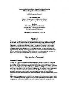
Figure 2.7: Wave packet size, σ, real radius of curvature, ρ, and ε, are shown as functions of time, t, for a two-disk periodic orbit. Disk radii a = 1, center-to-center separation R = 3, de Broglie wave length λ = 10−7 . The corresponding two-disk Lyapunov exponent λ/v ≈ 1.32. Initial wave packet size σ0 = 2 · 10−4 and ρ0 = 10. The particle is located in the middle between the two disks at t = 0. Exponential trends are shown for plots of σ and ε. All distances are measured in units of disk radius a. The parameters in fig. 2.7 are chosen so as to illustrate the essential regimes: a short decay of quantum effects (ε becomes less than unity), followed by the Lyapunov spreading of the wave packet, σ ∼ exp(λ(2) t), where λ(2) stands for the Lyapunov exponent of the two-disk unstable periodic orbit. The relatively small value of the de Broglie wavelength used in this example can be indeed achieved
27
experimentally [28]. The classical Lyapunov exponent of a two-disk periodic orbit is known exactly [30, 29], λ(2)
p R − a + R(R − 2a) v = ln . R − 2a a
(2.45)
Appendix A presents the derivation of the two-disk Lyapunov exponent by means of the radius of curvature method. In our case Eq. (2.45) gives λ(2) /v ≈ 1.32. The numerical evaluation presented in fig. 2.7 shows that a single collision is enough to initiate the exponential growth of the wave packet (with the rate given by the classical Lyapunov exponent), which persists for about 5-6 collisions. Our results do not apply for times longer than the duration of the Lyapunov regime, vtL /a ≈ 6. Before leaving the subject of wave packet propagation in the two-dimensional Lorentz gas, let us compare the classical and semiclassical finite time Lyapunov exponents, λcl t
v = t
Z
t 0
dτ ρcl τ
v λt = t
and
Z
t 0
dτ , ρτ
(2.46)
respectively, for the systems in the Lyapunov regime. Our previous analysis showed that the classical and semiclassical radii of curvature, ρcl t and ρt respectively, are almost identical after the first collision event taking place at a time t1 . Therefore, the difference in finite time Lyapunov exponents mainly results from the time interval (0, t1 ), during which the time evolution of the radii of curvature is given by ρcl t = ρ0 + vt
and
ρt =
(ρ0 + vt)2 + ε0 (vt)2 , ρ0 + vt + ε0 vt
(2.47)
where ρ0 is some initial value of the curvature radius, and ε0 is defined according to Eq. (2.40),
µ ε0 =
λρ0 2σ02
¶2 .
Assuming that the system is initially in the Lyapunov regime, ε0 ¿ 1, we expand 1/ρt in powers of ε0 to get 1 1 ρ0 vt = + ε0 + O(ε20 ). ρt ρ0 + vt (ρ0 + vt)3
28
(2.48)
Keeping only the first two terms in the expansion we estimate the difference between the semiclassical and classical finite time Lyapunov exponents: Z v t1 ρ0 vt cl λt − λt ≈ dτ ε0 t 0 (ρ0 + vt)3 µ ¶2 · µ ¶¸−2 ε0 vt1 λ2 1 1 2 = = 2σ0 + . 2t ρ0 + vt1 2t ρ0 vt1
(2.49)
Equation (2.49) shows that the semiclassical finite time Lyapunov exponent is larger than the classical one by a small amount which is proportional to the square of the de Broglie wavelength and inversely proportional to the time t. We also see that the difference in the Lyapunov exponents satisfies λt − λcl t < ε0 /2t ¿ 1/2t for the systems in the Lyapunov regime, and therefore is extremely small.
2.3 Propagator in three dimensions The derivation of the wave packet propagator presented in this chapter was carried out for hard-disk systems in two dimensions, d = 2. We now generalize this calculation to the three dimensional case, d = 3, using methods similar to those used to describe the classical separation of close trajectories [12, 27] The initial Gaussian wave packet in three dimensions reads ¶3/4 µ ¶1/2 1 1 hr|0i ≡ ψ0 (r) = 2π σk0 σ02 µ ¶ i ζ2 1 T −1 × exp ζ− − η Ω0 η , λ 4Ωk0 4 µ
(2.50)
where ζ-axis is directed along the momentum p0 , see fig. 2.2, while η ≡ (η (1) , η (2) )T lies in the plane perpendicular to p0 ; Ω0 is a 2 × 2 complex symmetric matrix, and T-superscript denotes transposition. As in two-dimensional case, the origin of the orthogonal frame (ζ, η (1) , η (2) ) travels with the center of the wavepacket with fixed axes, except at collisions, when the axes rotate so that the new ζ axis is in the direction of motion of the center of the wave packet, see fig. 2.2. The wave packet
29
2 size in ζ-direction σk0 = 1/ Re(Ω−1 k0 ), while in η-plane
1 . σ02 = p det Re(Ω−1 0 )
(2.51)
Application of the free streaming propagator Gfs (r, r0 , t), given by Eq. (2.6) with d = 3, to the wave function above changes Ω0 to i Ωt = Ω0 + λvt1, 2
(2.52)
where 1 is the 2 × 2 unit matrix; the change of the ζ-directional component of the wave packet is the same as in the two-dimensional case, Eq. (2.7). The single-sphere scattering propagator is given by Eq. (2.9) with d = 3. As in the two-dimensional problem, only the reflected path contributes to the propagator for a wave packet small compared to the sphere radius, a. Closely following the arguments of this chapter in three dimensions, one can verify that the scattering propagator Gsc (r, r0 , t) can be written as Z Z 0 ˆ 2 , r1 ) Gfs (r1 , r0 , t/2), Gsc (r, r , t) = dr1 dr2 Gfs (r, r2 , t/2) C(r
(2.53)
where, in order to simplify the algebra, we consider the case that the corresponding classical collision takes place at time t/2. The instantaneous collision transˆ when expressed in particle-fixed coordinate frames (ζ1 , η1(1) , η1(2) ) and formation C, (1)
(2)
(ζ2 , η2 , η2 ) just before and after the collision respectively, reads µ ¶ i T ˆ C(ζ2 , η 2 , ζ1 , η 1 ) = δ(ζ2 − ζ1 ) δ(η 2 − η 1 ) exp η Q(φ, θ)η 1 , λa 1 where
¸ 1 Q(φ, θ) = Pθ diag , cos φ PT θ, cos φ
(2.54)
·
and
Pθ =
(2.55)
cos θ − sin θ sin θ
cos θ
.
(2.56)
Here φ is the angle of incidence in the collision plane, see fig. 2.3, and θ is the (1)
azimuthal angle that η1 -axis makes with the collision plane. Note, that the coor(1)
(2)
(1)
(2)
dinate frames (ζ1 , η1 , η1 ) and (ζ2 , η2 , η2 ) are related to each other by the 3 × 3
30
reflection matrix (13 − 2nn), where 13 is the 3 × 3 unit matrix, and n stands for the three-dimensional collision vector, as illustrated in fig. 2.3. As seen from Eq. (2.54) the instantaneous collision does not affect Ωk , but changes the η-component of the wave packet according to Ω−1(+) = Ω−1(−) −
4i Q(φ, θ). λa
(2.57)
Introducing the radius of curvature matrix ρ˜ as i Ω ≡ λρ, ˜ 2
(2.58)
we obtain the three-dimensional equivalent of Eqs. (2.30) and (2.31),
ρ˜−1(+)
ρ˜t = ρ˜0 + vt1 2 = ρ˜−1(−) + Q(φ, θ) a
free streaming,
(2.59)
collision.
(2.60)
Both transformations preserve the symmetry of the complex matrix ρ. ˜ As in two-dimensional case, we consider a sequence of collisions parameterized by a set of times {tj } together with a set of collision angles {φj , θj }. Substitution of the free streaming transformation, Eq. (2.59), into the expression for the size of p the wave packet in the η-plane, σt2 = λ/(2 det Im ρ˜−1 t ), yields h i¯ ¯ à ! ¯ det ρ˜ + v(t − t )1 ¯ Z t j ¯ ¯ tj ¯ = σt2 exp v Re dτ trρ˜−1 σt2 = σt2j ¯¯ , (2.61) τ j ¯ det ρ ˜ tj tj ¯ ¯ for tj < t < tj+1 . Here we used the identity det Im ρ˜−1 = | det ρ| ˜ −2 det Im ρ, ˜
(2.62)
which can be straightforwardly verified for two-by-two symmetric matrices. By propagating σt backward in time we find µ ¶ Z t −1 2 2 = σ02 etht , σt = σ0 exp v Re dτ trρ˜τ
(2.63)
0
where σ0 characterizes the wave packet at t = 0, and Z t v ht = Re dτ trρ˜−1 τ . t 0
31
(2.64)
The quantity ht is a time-dependent stretching exponent, which describes growth of the area of wave packet cross section perpendicular to the direction of particle’s motion. It can be shown to converge in the long time classical limit to the classical Kolmogorov-Sinai (KS) entropy hKS , which is equal to the sum of all positive Lyapunov exponents in the infinite Lorentz gas system: X
lim lim ht = hKS =
t→∞ λ→0
λj .
(2.65)
λj >0
To complete the analogy with the two-dimensional problem we define a real radius of curvature matrix ρ and a real 2 × 2 matrix Σ in accordance with · ¸−1 iλ T −1 −1 ρ˜ ≡ ρ + (ΣΣ ) . (2.66) 2 It is easy to show that Σ determines the size σ of the wave packet, σ 2 = | det Σ|,
(2.67)
and is not affected by the collision transformation given by Eq. (2.60), while ρ satisfies ρ−1(+) = ρ−1(−) +
2 Q(φ, θ) a
(2.68)
at collisions. The free streaming time evolution of ρ and Σ is given by the differential equations 1 dρ =1− v dt
µ ¶2 λ ρ(ΣΣT )−2 ρ 2
and
1 dΣ = ρ−1 Σ, v dt
(2.69)
which are the three dimensional version of Eqs. (2.41). Since Σ+ = Σ− , the second equation in Eqs. (2.69) can be integrated to get µ Z t ¶ −1 Σt = T exp v dτ ρτ Σ0 ,
(2.70)
0
where T stands for the time ordering operator. Finally, taking the determinant of both sides of Eq. (2.70) we recover Eq. (2.63), namely σt2 = σ02 exp(tht ) with Z v t ht = dτ trρ−1 (2.71) τ . t 0
32
We conclude that the area (perpendicular to the probability current) of a small Gaussian wave packet grows exponentially with time. The rate of this growth is given by the sum of two positive Lyapunov exponents of the corresponding classical trajectory in three dimensions. In the case of an infinitely extended system this sum equals to the KS-entropy of the Lorentz gas. As in the two-dimensional case the theory presented here is valid only for times shorter than the Ehrenfest time at which the size of the wave packet becomes comparable to the scatterer size. We address the long time (beyond the Ehrenfest time) wave packet dynamics in Chapters IV and V.
33
Chapter 3 Periodic orbit revivals and the Loschmidt echo In this chapter we present two applications of the semiclassical short-time propagator for small Gaussian wave packets in the Lorentz gas derived above. As the first application, we calculate the wave packet autocorrelation function, or the particle return probability, for periodic orbits in the Lorentz gas. The time behavior of the autocorrelation function was earlier predicted and qualitatively described by Heller [13]. Our calculations confirm Heller’s predictions and provide further details for the autocorrelation function decay. Secondly, we derive an exact expression for the Loschmidt echo of a particular kind for a quantum particle moving in a hard-scatterer Lorentz gas. The Loschmidt echo, also known as fidelity, characterizes the sensitivity of quantum dynamics with respect to perturbations of system’s Hamiltonian. The particular type of the Loschmidt echo we consider deals with the Hamiltonian perturbation given by a small change of the mass of the moving particle. We show that there exists a close connection between this echo and the wave packet autocorrelation function in any hard-wall billiard system.
3.1 The wave packet autocorrelation function The wave packet autocorrelation function, also known as the particle return probability, C(t), is defined by C(t) = |h0|G(t)|0i|2 ,
34
(3.1)
with G(t) being the time-domain quantum propagator for a system of interest: µ ¶ i G(t) = exp − Ht . (3.2) ~ Here H is the Hamiltonian of the system and |0i is an initial quantum state. We will show that, for small Gaussian wave packets on periodic orbits and for times shorter than the Ehrenfest time, this function exhibits a series of maxima, with amplitudes decreasing mainly exponentially with time, as exp (−λt), where λ is the positive Lyapunov exponents for the corresponding periodic orbits in the two-dimensional Lorentz gas. The autocorrelation function maxima are separated by deep minima that appear for simple physical reasons, which will be explained later in this chapter. This type of decay of the autocorrelation function was first predicted by Heller [13]. The calculations presented here agree with Heller’s results and provide some additional information about the autocorrelation function, such as the value of C(t) between the neighboring wave packet reconstruction peaks and the coefficient in front of the exponential. This coefficient will be shown to have a sub-exponential time dependence. Let us now apply the wave packet dynamics developed in Chapter II, to calculate the wave packet auto-correlation function, C(t), defined in Eq. (3.1), for particles moving in periodic orbits of a two-dimensional Lorentz gas. Here the initial state, |0i, describes a Gaussian wave packet centered about a spatial point r0 with its average momentum p0 , such that the phase point (r0 , p0 ) lies on a periodic orbit of the corresponding classical system. The reasons for restricting our calculations to periodic orbits are as follows. The expansion used in the previous chapter to obtain the semiclassical single collision propagator in the previous chapter, Eq. (2.14), is correct for wave packets which are small compared to disk radii and average separation among scatterers. Mathematically, this limitation is a consequence of the truncation of the expansion of the coordinates of starting and final points connected by the propagator, r0 and
35
r respectively, about the centers of initial and final wave packets respectively, i.e. r0 = r00 + δr0 and r = r0 + δr. Therefore, one gets a close approximation to the particle’s wave function at positions close to the wave packet center, r0 , but the approximation may fail on the periphery of the wave packet. Our calculations of the auto-correlation function, C(t), are only reliable when the relevant overlap integrals are dominated by central region of the wave function, and contributions coming from wave packet wings can be neglected. This condition is most easily satisfied when the classical motion is along a periodic orbit.
∆ O
P
p0
Figure 3.1: A Gaussian wave packet is shown at time t = 0 (centered about point O), and at a later time t = nT + ∆/v (centered about point P ). Points O and P lie on the same periodic orbit, and are separated in time by n (= 0, 1, 2, . . . , N ) periods, T , of the periodic orbit, plus a short time interval ∆/v. The separation distance ∆ is assumed to be sufficiently small in order for the initial and final wave packets to overlap significantly. Consider a wave packet whose initial average coordinate, r0 , and momentum, p0 , correspond to a phase space point on a periodic orbit, with period T , of the classical Lorentz gas. Suppose that nT is smaller than the Ehrenfest time, for
36
n = 0, 1, 2, . . . , N so that we can apply the analysis developed in the previous section in order to propagate the wave packet over times t = nT + ∆/v,
(3.3)
where the displacement ∆ is sufficiently small in order for the initial and final wave packets to overlap significantly, as illustrated in fig. 3.1. For simplicity we take the initial wave function, ψ0 , to be a circularly symmetric Gaussian wave packet, i.e. σk0 = σ0 and ρk0 = ρ0 with the explicit form, µ µ ¶ ¶1/2 · ¸ 1 i 1 1 2i 2 2 ψ0 (x, y) = exp − − (x + y ) + x , 2πσ02 4 σ02 λρ0 λ
(3.4)
where x-axis is directed along p0 . In the same coordinate system the wave packet ψt propagated from ψ0 over time t, given by Eq. (3.3), reads, up to an irrelevant phase factor, µ ψt (x, y) =
1 2πσk σ
¶1/2
·
1 exp − 4
Ã
! 2i 1 − (x − ∆)2 σk2 λρk µ ¶ ¸ 1 1 2i i 2 − − y + (x − ∆) . 4 σ 2 λρ λ
(3.5)
Here, σk , σ, ρk and ρ depend on time t through a sequence of free flight and collision transformations developed in the previous chapter. The probability distribution |ψ0 (r)|2 is negligible outside a small circle of radius r ∼ σ0 . Therefore, the main contribution to the overlap hψ0 |ψt i comes from the points inside this circle, and the central regions of the wave packets dominate the integrals for small center-to-center separations ∆, as illustrated in fig. 3.1. A straightforward integration over r-space shows that for t given by Eq. (3.3) ¯2 ¯Z ¯ ¯ A ∗ (3.6) C(t) = ¯¯ dr ψ0 (r)ψt (r)¯¯ = exp(−α∆2 ), σ where 4 A = σ02
¯ ¯ ¯ gk g ¯ ¯ ¯ ¯ σk ¯ , " Ã
1 α = Re gk 2
(3.7) 2i 1 − 2 σk λρk
37
!µ
2i 1 + 2 σ0 λρ0
¶# ,
(3.8)
with µ ¶¸−1 1 1 2i 1 1 − g≡ 2+ 2− , σ σ0 λ ρ ρ0 " µ ¶#−1 1 1 1 2i 1 + − . gk ≡ − σk2 σ02 λ ρk ρ0 ·
(3.9)
As seen from Eq. (3.6) the auto-correlation function exhibits a sequence of peaks corresponding to partial reconstruction of the wave packet at times t = nT . These peaks, first predicted by Heller [13], have a simple physical origin: the wave packet repeatedly passes through the starting point giving rise to strong maxima of the return probability C(t). These maxima, known as periodic orbit revivals, should be distinguished from more general classes of quantum revivals that do not require a particular periodic orbit for their appearance [15]. One can see that time dependence of A and α is sub-exponential compared to to the exponential growth of σ with time, so that the periodic orbit revival peaks have predominantly Gaussian form, see fig. 3.2. Indeed, σk and ρk are not affected by collision events and change linearly with time. Furthermore, since σ grows exponentially with time, and ρ oscillates and stays bounded from both below and above, we see that g rapidly becomes an oscillating function of time. Thus, the strength of the autocorrelation function peaks decreases almost exponentially with time with a rate given by the Lyapunov exponent, λ, of the periodic orbit. This follows from the fact that, according to Eq. (3.6), height of the peaks is mainly determined by the exponential growth of the size of a wave packet, σ ∼ exp(λt). As one can see in fig. 3.2, the exact decay of the autocorrelation function envelope is slightly faster than exp(−λt) because of the power law decay of A. Figure 3.2 shows the numerical evaluation of the revivals in Eq. (3.6) for the two-disk periodic orbit described in previous section, see fig. 2.7. A particle of the de Broglie wavelength λ = 10−7 moves back and forth between two disks of radii a = 1, with the center-to-center separation R = 3, along the line connecting the centers. The initial wave packet is located in the middle between the two disks,
38
and is characterized by σk0 = σ0 = 2 · 10−4 and ρk0 = ρ0 = 10. The left part of fig. 3.2 shows the revival maxima Cmax , which occur at tmax = nT . The right part shows the auto-correlation function in small neighborhoods of the corresponding maxima. 0
0
10
10
Cmax , revival peak maxima
vtmax = 0
−1
−1
10
p(
ex t) −λ
−2
10
C , revival peaks
10
−3
vtmax = 2
−2
10
vt
max
=4
−3
10
10
vtmax = 6 −4
10
0
−4
2
4
10 −10−3
6
v tmax
0 v (t−tmax)
10−3
Figure 3.2: Revival peaks of the wave packet auto-correlation function, C(t), for the same two-disk periodic orbit as in fig. 2.7: a = 1 and R = 3. Particles de Broglie wave length λ = 10−7 . The initial wave packet is characterized by σ0 = σk0 = 2 · 10−4 and ρ0 = ρk0 = 10. The exponential trend is indicated by a straight line. It easy to show that in case of the two-disk periodic orbit, the revival peaks are separated by deep minima of the autocorrelation function. The minima occur when the average momenta of the original wave packet and the one propagated in time t are pointing in opposite directions. When this happens, ψ0 and ψt interfere destructively, and the auto-correlation integral, C(t), is very small. We calculate
39
the overlap of ψ0 and ψt at t = (n+1/2)T , when the two wave packets are centered about the same point, but move in opposite directions. The initial wave function is given by Eq. (3.4), while à ! # " ¶1/2 µ ¶ µ 2i 1 1 2i 1 1 i 1 2 2 − x − − ψt (x, y) = exp − y − x . 2πσk σ 4 σk2 λρk 4 σ 2 λρ λ (3.10) Then,
¯2 ¯Z ¶ µ ¯ ¯ A 2 ∗ ¯ ¯ C(t) = ¯ dr ψ0 (r)ψt (r)¯ = exp − 2 Re gk , (3.11) σ λ where A and gk are defined in Eqs. (3.7, 3.9). It can be shown that the exponential in Eq. (3.11) is a very small number if the condition λ ¿ σ0 , ρ0 is satisfied, e.g. in case of the periodic orbit considered above (fig. 2.7 and fig. 3.2) Re gk ranges from 2 · 10−8 to 4 · 10−8 making C(t) smaller than (A/σ) exp(−4 · 106 ), which is practically zero when compared with values of C(t) at the periodic orbit revival maxima. Similar deep minima of the autocorrelation function will occur for particles in more complicated periodic orbits, making the revivals very pronounced.
3.2 Mass perturbation Loschmidt echo The calculation of the autocorrelation function presented in the previous section is limited in applicability to times less than the Ehrenfest time, which is the time necessary for a wave packet to spread to the size of a scatterer. However, there is an application of this result to the Loschmidt echo of a special type which is valid for a much longer time interval, greater than the Ehrenfest time. The Loschmidt echo, also known as quantum fidelity, [16, 17, 18], ML (t), is defined by
¯ ¶ µ ¶ ¯2 µ ¯ ¯ i i ¯ (H + δH)t exp − Ht |0i¯¯ . ML (t) = ¯h0| exp ~ ~
(3.12)
Here H is the Hamiltonian for the system, δH is a small perturbing Hamiltonian, and |0i is some initial quantum state. The Loschmidt echo is the probability for
40
a quantum system to return to its initial state when a Hamiltonian evolution for time t is followed by a time-reversed evolution for the same time period under a slightly different Hamiltonian. Another way to look at this quantity is to say that the ML (t) compares two quantum states: one obtained from |0i by propagating it over time t under Hamiltonian H, and the other obtained for the same initial state by time t propagation under a modified Hamiltonian H + δH. The time decay of the Loschmidt echo for certain perturbations is known to be related to the Lyapunov exponents of classically chaotic systems [17, 18]. Here we provide an exact result for the Lorentz gas Loschmidt echo with a particular Hamiltonian perturbation. For the case that H is the Lorentz gas Hamiltonian with hard-wall scatterers, and the perturbation is a small change in the mass of the moving particle, it is straightforward to show that ML (t) is equal to the wave packet autocorrelation function evaluated at a scaled time, which can be made to be much shorter than the physical time t, by choosing a suitably small mass perturbation. Therefore for this special perturbation and hard scatterer Lorentz gas system, the quantum fidelity can be evaluated for very long times, if one knows the behavior of the autocorrelation function for a much shorter time interval. Let us now describe the Hamiltonian perturbation of the Loschmidt echo defined by Eq. (3.12). We suppose that the perturbed Hamiltonian is obtained from the unperturbed one by changing the mass of the moving particle, from m to m + δm. The identity depends on the fact that for hard scatterers, no matter what their shape, the eigenfunctions depend on wave numbers rather than on the mass of the moving particle. That is, the sets of eigenfunctions for particles of different masses are the same, only the values of the energy corresponding to the same wave numbers differ. The wave functions are the solutions of the scalar Helmholtz equation
¡
¢ ∇2 + k 2 φk (r) = 0
41
(3.13)
which satisfy the Dirichlet boundary condition that φk (r) vanishes on the surface of each scatterer, and on the boundaries of the system. We can express the time propagator for a moving particle of mass m under a Hamiltonian Hm as µ
it exp − Hm ~
¶ =
X k
µ
¶ i~t 2 |φk i exp − k hφk |, 2m
(3.14)
where the summation is over all possible eigenstates of the system. These eigenstates, |φk i, satisfy an orthonormality relation hφk0 |φk i = δk0 ,k ,
(3.15)
where the choice between Kronecker and Dirac delta functions is dictated by the nature of the eigenstates. Eqs. (3.14, 3.15) hold for systems with hard wall potentials in any number of spatial dimensions. This representation of the time displacement operator, Eq. (3.14), together with the orthonormality condition, Eq. (3.15), leads to the following identity µ ¶ µ ¶ µ ¶ it it its Hm+δm exp − Hm = exp − Hm , exp (3.16) ~ ~ ~ where ts is a scaled time, related to the physical time t by ts =
δm t. m + δm
(3.17)
This identity permits us to express the Loschmidt echo, for this special perturbation, in terms of the wave packet autocorrelation function as ¯ µ ¶ µ ¶ ¯2 ¯ ¯ it it ML (t) = ¯¯h0| exp Hm+δm exp − Hm |0i¯¯ ~ ~ ¯ µ ¶ ¯2 ¯ ¯ its = ¯¯h0| exp − Hm |0i¯¯ = C(ts ). ~
(3.18)
This is the main result of this section. For small perturbations, δm/m ¿ 1, the Loschmidt echo for long times can be expressed in terms of the short time autocorrelation function.
42
The physical origin of this result is straightforward. Classically, the perturbed and unperturbed masses follow exactly the same trajectory, but with different velocities. Hence the forward motion with mass m followed by the reversed motion with mass m+δm has a final position that is different from the initial position, and corresponds to motion over the part of the path that is not reached by the time reversed trajectory. This is exactly reflected by the operator identity, Eq. (3.16). Perhaps the most remarkable thing about this result is the fact that although for long times a small wave packet will spread over large distances, the Loschmidt echo in this case is determined by the short time spreading of the wave packet, even if the physical time is quite large. As discussed in the previous section, the autocorrelation function C(t) exhibits a sequence of sharp revival maxima when the particle moves on a classically periodic orbit. The maxima occur at times tmax multiples of the period T of the periodic orbit, and C(tmax ) ∼ exp(−λtmax ), where λ is the corresponding classical Lyapunov exponent. According to Eq. (3.18) the mass perturbation Loschmidt echo ML at time t is simply the autocorrelation function C at the scaled time ts given by Eq. (3.17). Thus, like the autocorrelation function, the Loschmidt echo ML (t) exhibits a periodic sequence of maxima at times t0max =
m + δm m + δm tmax = n T, δm δm
(3.19)
where n = 1, 2, . . . , N , such that N T is smaller than the duration of the Lyapunov regime, tL . The envelope of the maxima exhibits a mainly exponential decay: ML (t0max ) = C(tmax ) ∼ exp(−λtmax ) = exp(−λs t0max ).
(3.20)
Here we introduced a scaled Lyapunov exponent according to λs =
δm λ. m + δm
(3.21)
It is important to note that the behavior of the Loschmidt echo described by Eq. (3.20) can persist for times much longer than tL (for sufficiently small δm)
43
despite the fact that the analysis of the wave packet dynamics presented in Chapter II is valid only for times shorter than tL . The Hamiltonian perturbation used in this section is rather trivial since the perturbed Hamiltonian commutes with the unperturbed Hamiltonian. Therefore the results of this section are not to be compared with those obtained for more complicated perturbations such as distortion of the mass tensor [17, 18].
44
Chapter 4 The Lorentz gas in high-energy diffraction regime Having described the short time behavior of small Gaussian wave packets in the semiclassical Lorentz gas we turn our attention to the long time evolution of spatially extended wave functions. In this chapter, we derive the long time quantum propagator for a dilute Lorentz gas system with hard-disk scatterers using the method of the multiple collision expansion [32, 33]. Then, we apply this propagator to an initially localized wave packet, corresponding to a highly-energetic particle, and calculate the long time autocorrelation function for this wave packet. The time decay of the autocorrelation function turns out to be exponential, with the decay rate governed, to a large extent, by such properties of the corresponding classical Lorentz gas system as the mean Lyapunov exponents and the Kolmogorov-Sinai entropy. We also observe a sequence of well pronounced peaks in the autocorrelation function due to partial reconstruction of the wave packet.
4.1 Energy-dependent propagator for the Lorentz gas We consider a particle of mass m placed among a collection of N fixed hard-disk scatterers of radius a centered at position vectors Rj , with j = 1, 2, . . . , N . The Hamiltonian of the system can be written as H = H0 +
N X j=1
45
Vj ,
(4.1)
where H0 is the free particle Hamiltonian, and the hard-disk scatterer potentials are given by
+∞ Vj (r) = 0
for |r − Rj | < a, for |r − Rj | ≥ a.
(4.2)
The time-domain propagator G(t) satisfying the Schr¨odinger equation with the Hamiltonian given by Eqs. (4.1) and (4.2) can be formally expressed as µ ¶ i G(t) = exp − Ht . ~
(4.3)
Instead of working with the time-dependent propagator, one can construct the energy-domain propagator which is related to G(t) by the positive time Fourier transform 1 G(E) = i~
Z
+∞
dtei(E+i0)t/~ G(t) =
0
1 . E − H + i0
(4.4)
The inverse transform is given by i G(t) = 2π
Z
+∞
dEe−iEt/~ G(E),
(4.5)
−∞
where we consider time t to be strictly positive. The appeal of dealing with the energy propagator G(E) is motivated by a method of quantum scattering theory called the multiple collision (or multiple scattering) expansion [32, 33]. The multiple collision expansion of the energy-dependent propagator represents G(E) as an infinite sum over possible collision sequences that the quantum particle can undergo: G = G0 +
X j
G0 Tj G0 +
XX j
G0 Tj G0 Tk G0 +
XXX j
k6=j
G0 Tj G0 Tk G0 Tl G0 + . . . ,
k6=j l6=k
(4.6) where G0 =
1 E − H0 + i0
(4.7)
is the free particle propagator in the energy domain, and the binary collision operator, Tj , also known as the T-matrix, is defined by the multiple collision expansion,
46
Eq. (4.6), written for a system containing only the j th scatterer, i.e. Gj ≡
1 = G0 + G0 Tj G0 . E − H0 − Vj + i0
(4.8)
Hereinafter all G and T operators are given in the energy domain unless the time dependence is specified explicitly. Here, Gj is the propagator for a particle moving in two dimensional space with only one scatterer located at point Rj . Equation (4.6) represents the full quantum propagator G in a way that is useful for calculation of the autocorrelation function overlap h0|G|0i. According to Eq. (4.6) one can first separately calculate the autocorrelation function overlaps due to each term in the RHS, and then sum the resulting overlaps to get the total autocorrelation function. This method is useful for the Lorentz gas-like billiard systems which contain only a small number of scatterers. For such billiard systems the series due to the multiple collision expansion allows explicit summation. Before going into the details of this summation let us first derive the matrix elements of the energy-dependent propagator G given by Eq. (4.6). The hard disk binary collision operator Tj was calculated by Correia [34] following a method proposed by Schick [35]. The idea of the method is to express the T-matrix Tj in terms of the full one scatterer propagator Gj and the scatterer potential Vj by means of the Dyson expansion [36], Gj = G0 + G0 Vj Gj .
(4.9)
Comparison of Eqs. (4.8) and (4.9) yields the desired relation: Tj = Vj + Vj Gj Vj .
(4.10)
The matrix elements of operators Gj and Vj are then calculated for a disk-scatterer of a finite potential hight, so that the matrix elements of the binary collision operator are well defined. The limit of the infinitely high disk potential is taken at the last step to obtain the matrix elements of Tj for a hard-disk scatterer.
47
For a particle of energy E = ~2 κ2 /2m, where κ stands for the magnitude of the particle’s wave vector, the matrix element hk|Tj |k0 i of the binary collision operator, relating two generally different momentum states k and k0 , is given by +∞ ~2 −i(k−k0 )Rj X il(θk −θk0 ) hk|Tj |k i = 2πa e e 2m l=−∞ ½ 0 2 2 (k ) − κ 0 × [k Jl (ka)Jl−1 (k 0 a) − kJl−1 (ka)Jl (k 0 a)] 2 0 2 k − (k ) 0
(4.11)
(1)
0
0
0
+k Jl (ka)Jl−1 (k a) − κJl (ka)Jl (k a)
Hl−1 (κa) (1)
Hl (κa)
) ,
where (k, θk ) and (k 0 , θk0 ) are the polar coordinates of the wave vectors k and k0 (1)
respectively, Jl is the Bessel function of the first kind of order l, Hl
is the Hankel
function of the first kind of order l. Appendix B presents the derivation due to Correia [34] of the matrix element given by Eq. (4.11). Hereinafter, we adopt the following normalization conditions to specify the position and momentum states: hr|r0 i = δ(r − r0 ),
hk|k0 i = (2π)2 δ(k − k0 )
so that the completeness relations read Z dr|rihr| = 1 and
1 (2π)2
and
hr|ki = eikr ,
(4.12)
Z dk|kihk| = 1.
(4.13)
Equation (4.11) together with the expression for the free particle propagator matrix element, hk|G0 |k0 i =
2m δ(k − k0 ) , ~2 κ2 − k 2 + i0
(4.14)
allows one to calculate the matrix element describing a sequence of n successive
48
p q
R jp
R qr
j
r
R ij
i
R rs
k
s
k’ Figure 4.1: Schematic sketch of a particle collision sequence corresponding to the matrix element in Eq. (4.15). collisions of the particle with scatterers s, r, q, . . . , p, j and i, see fig. 4.1: ~2 −ikRi +ik0 Rs hk|Ti G0 Tj G0 Tp G0 . . . Tq G0 Tr G0 Ts |k0 i = (−1)n 4i e 2m " # +∞ X Jli (ka) ili (θk −θij +π/2) (1) × e Hli −lj (κRij ) (1) li ,lj ,lp ...,lq ,lr ,ls =−∞ Hli (κa) " # Jlj (κa) ilj (θij −θjp ) (1) × e Hlj −lp (κRjp ) . . . (1) Hl (κa) " j # " # 0 Jlr (κa) ilr (θqr −θrs ) J (k a) l (1) s × e Hlr −ls (κRrs ) eils (θrs −θk0 −π/2) . (1) (1) Hlr (κa) Hls (κa) (4.15) Here (Rij , θij ) are the polar coordinates of the scatterer separation vectors Rij ≡ Ri − Rj , where i, j = 1, 2, 3, . . . , N . The matrix element of the product of operators, given by Eq. (4.15), is obtained in the result of a straightforward integration of the product of corresponding matrix elements over the momentum space: 1 hk|AB|k i = (2π)2 0
Z dk00 hk|A|k00 ihk00 |B|k0 i.
Reference [34] provides with the details of the momentum-space integration. We will now calculate the autocorrelation function for an initially localized
49
wave packet |φ0 i using the binary collision expansion presented in Eq. (4.6) and matrix elements for a collision sequence given by Eq. (4.15).
4.2 Autocorrelation function in the energy domain Let us now specify the wave packet which we will use to calculate the autocorrelation function due to the propagator described by Eqs. (4.6) and (4.15). Although commonly used, a Gaussian wave packet would not constitute an appropriate choice, since in a hard-scatterer Lorentz gas it represents an unphysical state of infinite energy: the wings of the Gaussian wave packet, no matter how small, penetrate the disk scatterers and thus make an infinitely large contribution to the potential energy of the system1 . Instead we choose a circular wave packet defined by eik0 r φ0 (r) = √ Θ(σ − |r − R0 |). πσ 2
(4.16)
The wave packet represents a particle, with the average momentum ~k0 , located at the position R0 . Here Θ is the step function, and the real quantity σ has an apparent meaning of the wave packet dispersion. We will see at the end of this chapter and in the next chapter that the time decay of the wave packet autocorrelation function does not depend significantly on the initial wave packet, as long as the latter is sufficiently localized in the momentum space. For the sake of simplicity we fix the system of coordinate by imposing R0 = 0, so that the particle is initially located at the origin. The circular wave packet does not overlap with the disk scatterers if the following N conditions are satisfied: Rj > a + σ, 1
for j = 1, 2, 3, . . . , N.
(4.17)
Mathematically, the unphysicality of the Gaussian state shows up as divergence of the integral
determining the time-domain scattering part of the autocorrelation function, see Eq. (4.33) below.
50
The momentum representation of the wave packet is given by √ J1 (|k − k0 |σ) φ0 (k, k0 ) = 2 π |k − k0 | ≡ φ0 (k, k0 ; θk − θk0 ) =
+∞ X
(4.18) il(θk −θk0 )
χl (k, k0 )e
,
l=−∞
with
√ kJl+1 (kσ)Jl (k0 σ) − k0 Jl (kσ)Jl+1 (k0 σ) . χl (k, k0 ) = 2 π k 2 − k02
(4.19)
Here (k0 , θk0 ) are the polar coordinates of the wave vector k0 . Performing the integration over the k-space we calculate the part of the wave packet autocorrelation function due to a sequence of n successive collisions of the particle initially at R0 with scatterers s, r, q, . . . , p, j and i: hφ0 |G0 Ti G0 Tj G0 Tp G0 . . . Tq G0 Tr G0 Ts G0 |φ0 i +∞ X £ ¤ (1) 1 2m il(θ0i −θk0 −π/2) ∗ = (−1) χ (κ, k )e Hl−li (κR0i ) l 0 4i ~2 l,l ,...,l ,l0 =−∞ s i # " # " Jlj (κa) ilj (θij −θjp ) Jli (κa) ili (θ0i −θij ) (1) (1) e Hli −lj (κRij ) e Hlj −lp (κRjp ) . . . × (1) (1) Hli (κa) Hlj (κa) " # h i Jls (κa) ils (θrs −θs0 ) (1) il0 (θs0 −θk0 −π/2) 0 × e H (κR ) χ (κ, k )e . s0 l 0 ls −l0 (1) Hls (κa) n
(4.20) The polar coordinates of the disk separation vectors R0i ≡ R0 − Ri and Rs0 ≡ Rs − R0 are given by (R0i , θ0i ) and (Rs0 , θs0 ) respectively; the asterix denotes the complex conjugate. The expression for the overlap in Eq. (4.20) is exact. We will now derive an approximation of this overlap for the case of a dilute scattering system. In the dilute Lorentz gas, Rij À a, the high argument exponential approximation for the Hankel functions, that appear in Eq. (4.20), can be used to greatly simplify the analysis of the autocorrelation function. Let us start with determining the angular momentum states dominating the autocorrelation function for a given value of κ. The ratios inside the brackets in
51
(1)
Eq. (4.20), Jl (x)/Hl (x), are small for l > x, since Jl (x) has its first maximum at x ∼ l. Consequently, the main contribution to the multiple sum in Eq. (4.20) comes from terms with li , lj , . . . , ls running from −[κa] to +[κa], and l, l0 running from −[κσ] to +[κσ], where the square brackets denote the integer part. At the same time, the large argument approximation of the Hankel function [37], r ¶¸ · µ 2 πl (1) Hl (x) ≈ exp i x − , (4.21) πix 2 holds for 1 xÀ 2
µ
1 l − 4 2
¶ .
(4.22)
Therefore, if κRij À (2κa)2 /2, and κR0i , κRs0 À (κa + κσ)2 /2 we can use this approximation in Eq. (4.20) to get µ ¶1/2 i m hφ0 |G0 Ti G0 Tj G0 . . .Tr G0 Ts G0 |φ0 i ≈ − 2 ~ 2πκ eiκRij eiκR0i × φ∗0 (κ, k0 ; θ0i − θk0 ) √ fκ (θ0i − θij ) p ... R0i Rij
(4.23)
eiκRs0 × fκ (θrs − θs0 ) √ φ0 (κ, k0 ; θs0 − θk0 ), Rs0 where
µ fκ (θ) = −
2 πiκ
¶1/2 X +∞
Jl (κa)
(1) l=−∞ Hl (κa)
eilθ
(4.24)
is the scattering amplitude [33] describing scattering of a quantum particle of energy E = ~2 κ2 /2m from a hard disk of radius a at an angle θ. The approximation given by Eq. (4.23) is only valid for energies satisfying the conditions (see Eq. (4.22) and the discussion right below it) κ¿
2R0i Rij , 2 2a (a + σ)2
for i, j = 1, 2, 3, . . . , N.
(4.25)
These conditions have a simple physical meaning. Suppose Rij , R0i ∼ R and σ ∼ a, then Eq. (4.25) can be written as R À 2a/α, with α = 1/κa. The latter has a meaning of the angle of diffraction of a wave with the wave length 1/κ on an obstacle of size a, so that 2a/α represents the estimate of the shadow depth,
52
which is the largest distance that geometrical shadow can survive. Thus, the conditions (4.25) imply that Eq. (4.23) is only valid in the diffraction regime, i.e. no disk scatterer can be screened from the particle by other disks. In the case of a dilute scattering system, R À a, the inequality (4.25) is satisfied for a significant range of energies, so that Eq. (4.23) is a good approximation of the autocorrelation function for wave packets in the energy range specified by Eq. (4.25). Suppose the wave packet φ0 given by Eq. (4.18) is well localized in momentum space, i.e. the particle’s de Broglie wave length λ ≡ 1/k0 ¿ σ . Then, the overlap given by Eq. (4.23) is negligible unless θ0i ≈ θs0 ≈ θk0 . Indeed, φ0 (k, k0 ; θ), if considered as a function of the angle θ between k and k0 , is sharply peaked at θ = 0, and rapidly vanishes as k turns away from k0 . This means that the wave packet autocorrelation function hφ0 |G|φ0 i gets a significant scattering contribution hφ0 |G0 |φ0 i only if the wave packet is initially located on and moves along a line connecting centers of any two disks in the scattering system! It is because the reflection wave produced by a disk at the last scattering interferes destructively with the initial wave unless the two waves have their wave vectors pointing almost in the same direction. This effect is reminiscent of the phenomenon of eigenfunction “scarring” in closed chaotic billiards along classically unstable periodic orbits [38, 39].
4.3 Time-domain autocorrelation function In this section we calculate the autocorrelation function for the circular wave packet defined by Eq. (4.16) in three different scattering systems: two-disk, three-disk “equilateral” and three-disk “isosceles” billiards. The autocorrelation function overlap in the energy domain can be written as hφ0 |G|φ0 i = hφ0 |G0 |φ0 i + S(E),
53
(4.26)
where the scattering part of the autocorrelation function, S(E), is determined by all possible collision events: X XX S(E) = hφ0 |G0 Tj G0 |φ0 i + hφ0 |G0 Tj G0 Tk G0 |φ0 i j
j
+
k6=j
XXX j
(4.27) hφ0 |G0 Tj G0 Tk G0 Tl G0 |φ0 i + . . . .
k6=j l6=k
We will now sum this series explicitly for the three billiard systems using the diffraction regime approximation, Eq. (4.23), together with the assumption of a high-energetic wave packet as will be described below.
4.3.1 Two-disk billiard
r1
r2 k0
1
2
Figure 4.2: Two-disk billiard. The circular wave packet is initially located on the classically periodic orbit distance r1 away from disk “1”, and distance r2 away from disk “2”, with r1 + r2 = R. The two-disk billiard consists of two hard disks, “1” and “2”, of radius a with the center-to-center separation R, see fig. 4.2. As discussed in the previous section the wave packet should be initially placed on the line connecting the disk centers with its wave vector k0 pointing along this line in order for the sum in Eq. (4.27) to have significant, non-vanishing terms. For the initial condition shown in fig. 4.2 these non-vanishing terms are
µ ¶1/2 m i hφ0 |G0 T1 G0 T2 G0 . . .T1 G0 T2 G0 |φ0 i = − 2 |φ0 (κ, k0 ; 0)|2 ~ 2πκ eiκR eiκr1 eiκR eiκR eiκr2 × √ fκ (π) √ fκ (π) √ . . . fκ (π) √ fκ (π) √ , r1 r2 R R R
54
(4.28)
where the diffraction regime approximation, Eq. (4.23), has been used. Here, r1 and r2 are the distances separating the center of the wave packet and the centers of disks “1” and “2” respectively; r1 + r2 = R. Substitution of Eq. (4.28) into Eq. (4.27) yields µ ¶1/2 ¶2n +∞ µ X eiκR m iR 2 S(E) = − 2 |φ0 (κ, k0 ; 0)| fκ (π) √ ~ 2πκr1 r2 R n=1 µ ¶1/2 m iR |φ0 (κ, k0 ; 0)|2 = 2 ¶−2 . µ ~ 2πκr1 r2 eiκR 1 − fκ (π) √ R
(4.29)
Equation (4.25) along with the assumption r1 ∼ r2 ∼ R/2 shows that the validity of the result predicted by Eq. (4.29) is limited to the energies satisfying κ ¿ R/2a2 , R/(a + σ)2 . Now, if the wave packet is sufficiently localized in momentum space, i.e. the de Broglie wave length λ = 1/k0 ¿ σ, and if k0 ¿ R/2a2 , R/(a+σ)2 , then Eq. (4.29) can be used to calculate the time domain autocorrelation function for the wave packet. We are going to make one more assumption, namely λ ¿ a, in order to use the semiclassical (WKB) expression for the hard-disk scattering amplitude. This assumption says that we only consider high-energetic particles for which the scattering amplitude can be written as r a fκ (θ) = − | sin(θ/2)| e−2iκa| sin(θ/2)| . 2
(4.30)
Equation (4.30) is known to be a good approximation of the exact scattering amplitude for sufficiently large scattering angles [40]. Summarizing, the time dependent autocorrelation function to be calculated below refers to hard-disk billiard systems in the high-energy diffraction regime: 2a2 (a + σ)2 , ¿ λ ¿ a, σ R R
(4.31)
This condition can be easily satisfied for a sufficiently dilute billiard system, for which R À a, see fig. 4.3. The condition given by Eq. (4.31) can be also formulated
55
in the following way: we only consider such wave packets that can be represented, to a high accuracy, by a superposition of states with energies E = ~2 κ2 /2m, where κ satisfies R 1 R ¿ κ ¿ 2, . a 2a (a + σ)2
(4.32)
The calculation of the scattering part of the autocorrelation function in the time domain, S(t), proceeds as follows. According to Eq. (4.5) the energy-time domain transformation reads i ~2 S(t) = 2π m
Z
µ
¶ ~t 2 dκκ exp −i κ S(E), 2m Γ
(4.33)
where S(E) is given by Eq. (4.29), and contour Γ consists of two straight segments, which lead from −i∞ through 0 to +∞. The expression, obtained for the autocorrelation function S(E), is only valid in the energy range specified by Eq. (4.32). Therefore, the time-domain autocorrelation function S(t) calculated in accordance with Eq. (4.33) will fail for short times, corresponding to high energies with k & R/2a2 , R/(a + σ)2 , and for long times, corresponding to low energies with k . 1/a. Careful analytical calculation of a range of times, for which Eq. (4.33) gives accurate predictions, is a formidable problem. Nevertheless, we can use simple physical arguments to roughly estimate this time range. The method that we used to calculate the energy-dependent scattering part of the autocorrelation function, S(E), relies on the assumption of the wave packet diffraction. The wave packet must explore the scattering system for the diffraction effects to take place. An estimate of the time needed for the particle to reach the first scatterer is tE ≈ r2 /v ∼ R/v, where r2 is the distance between the initial location of the particle and the first scatterer it collides with, see fig. 4.2, and v = ~k0 /m is the average velocity of the wave packet. Time tE also gives an estimate of the Ehrenfest time for the system: for times shorter than tE the wave packet evolution is dominated by the free particle Hamiltonian, and therefore is classical-like, while particle’s propagation is diffractive and substantially non-classical for times beyond tE . To
56
estimate the upper bound of the applicability time range of Eq. (4.33), with S(E) given by Eq. (4.29), we note that the expression for S(E) breaks down at energies E = ~2 κ2 /2m with κ ∼ 1/a. The momentum corresponding to these energies is ~κ ∼ (λ/a)~k0 , and the corresponding velocity is vκ ∼ (λ/a)v. The contribution of these low energy modes of the particle to the autocorrelation function become significant after the long wavelength part of the wave packet explores the scattering system, i.e. after times tmax ∼ R/vκ ∼ (a/λ)R/v corresponding to a/λ particledisk collisions. Since, a À λ this number of collisions can be quite large. In order to evaluate the integral in Eq. (4.33) one can show that for t > 0 the contour can be closed along the infinite quarter-circle κ = +∞ eiγ with 3π/2 < γ < 2π, so that the value of the integral is determined by poles of S(E) in the fourth quadrant of the complex κ plane: κn =
πn i 2R − ln , R 2R a
for n = 1, 2, 3, . . . .
(4.34)
The semiclassical approximation for the scattering amplitude, Eq. (4.30), was used to find zeros of the denominator of S(E), so that Eq. (4.34) correctly locates the poles right below the region on real κ axis where φ0 (κ, k0 ; 0) is localized. Then, calculating the residues corresponding to the poles, we get 1 S(t) ≈ (2πiRr1 r2 )−1/2 2
n0 +[R/σ]
X
n ∼ n0 −[R/σ]
√
µ
¶ ~t 2 κn |φ0 (κn , k0 ; 0)| exp −i κ , 2m n 2
(4.35)
where πn0 /R = k0 , and the square brackets represent the integer part. Equation (4.35) is expected to fail for short times t where the dynamics is determined by values of S(E) at high energies at which the diffraction regime approximation breaks down, as well as for times t → ∞ which would require to go beyond the WKB approximation for the scattering amplitude fκ (θ). Equation (4.35) is valid for times greater than the Ehrenfest time, tE ≈ r2 /v, with v = ~k0 /m representing the velocity of the corresponding classical particle; the evolution of the wave packet is substantially non-classical for times beyond the Ehrenfest limit.
57
The free streaming part of the autocorrelation function overlap, hφ0 |G0 (t)|φ0 i, can be calculated explicitly for the propagator given by Eq. (2.6). As we show in Appendix C, the free motion contribution to the full autocorrelation function C(t) is negligible for dilute billiard systems we are dealing with. Thus, the autocorrelation function for long times is entirely determined by the scattering events, so that one can write C(t) = |hφ0 |G(t)|φ0 i|2 ≈ |S(t)|2 .
(4.36)
The main features of the time-domain autocorrelation function C(t) can be deduced by considering only a small number of poles with n = n0 + n ˜ , where n ˜ is sufficiently small, so that the pre-exponential function in Eq. (4.35) stays approximately constant. The contribution due to these poles is " µ ¶2 # X ~t π˜ n i 2R exp −i S(t) ∼ k0 + − ln 2m R 2R a n ˜ ¶X µ vt 1 e−i R π˜n , ∼ e−iE0 t/~ exp − λ(2) t 2 n ˜
(4.37)
where E0 = ~2 k02 /2m is the average energy of the wave packet, v = ~k0 /m is its average velocity, and λ(2) =
v 2R ln R a
(4.38)
is the classical Lyapunov exponent of the two-disk periodic orbit [29]. Equation (4.37) shows that (i) the envelope of the scattering part of the autocorrelation function decays exponentially with time, C(t) ∼ e−λ
(2) t
, with the decay rate given
by the classical Lyapunov exponent of the system, and (ii) strong interference (revival) peaks occur in C(t) at times t multiple to the period of the classical periodic orbit, i.e. when vt/R is an even integer. Figure 4.3 shows the autocorrelation function, C(t), directly computed from Eq. (4.35),with the wave packet given by Eq. (4.18), for the two-disk billiard with the following parameters: a = 1 and R = 104 . The circular wave packet of size σ = 1 is initially placed in the middle between the disks, r1 = r2 = R/2, and its de
58
−10
10
−20
C(t)
10
−30
10
−40
10
−50
10
−60
10
1
2
3
4
5
6
7
8
9
10
11
vt/R
Figure 4.3: Absolute value squared of the scattering part of the autocorrelation function C(t) as a function of vt/R for the two-disk billiard. Parameters of the system are as follows: a = σ = 1, R = 104 , r1 = r2 = R/2 and λ = 10−2 . The straight line shows exponential decay with the rate given by the classical two-disk Lyapunov exponent λ(2) . The decay is shown for times t greater than the Ehrenfest time tE ≈ R/2v. Broglie wave length λ = 10−2 . Conditions (4.31) are satisfied by this system. The summation in Eq. (4.35) includes 20,001 poles. The solid line shows e−λ
(2) t
decay.
The Ehrenfest time for the system tE ≈ R/2v.
4.3.2 Three-disk “equilateral” billiard Now we address different scattering systems, namely three-disk billiards. In these systems a particle moves in two dimensional space with only three hard-disk scatterers. In this chapter we consider only such three-disk billiards for which the
59
centers of the disks are vertices of an equilateral or an isosceles triangle. The corresponding scattering systems are then called the three-disk “equilateral” and “isosceles” billiards. The most general case, in which all three sides of the triangle are different is called a generic three-disk billiard and will be considered in the next chapter.
3
αR
αR
k0
1 r1
2 r2
Figure 4.4: Three-disk “isosceles” billiard. The circular wave packet is initially located distance r1 away from disk “1”, and distance r2 away from disk “2”, with r1 + r2 = R. Disk “3” is distance αR away from disks “1” and “2”. The “equilateral” billiard case corresponds to α = 1. Consider a billiard consisting of three hard disks of radius a centered at the vertices of an isosceles triangle with one side of length R and two other sides of length αR, see fig. 4.4. In this section we focus on the “equilateral” billiard (α = 1), which allows complete analytical treatment. The following section is devoted to the “isosceles” billiard case (α 6= 1), for which a substantial understanding can be
60
achieved in the limit α À 1. Our calculation of the autocorrelation function for a wave packet in the threedisk “equilateral” billiard employs the matrix method by Gaspard and Rice [21]. As in the case of the two-disk billiard we initially put the wave packet of size σ on the line connecting the center of two disks, labeled by “1” and “2”, with center-to-center separation R, see fig. 4.4. Distances r1 and r2 separating the wave packet center and the centers of disks “1” and “2” respectively satisfy the apparent condition: r1 + r2 = R. The average wave vector of the wave packet k0 is pointing along the line connecting the centers of disks “1” and “2”; the third disk of the billiard is labeled by “3” and stands distance αR away from the first two disks. For the three-disk billiard the multiple collision expansion given by Eq. (4.27) reads S(E) =
∞ X X
hφ0 |G0 T1 G0 Ti G0 Tj . . . G0 T2 G0 |φ0 i,
(4.39)
n=2 path(n)
where the second sum runs over all possible paths consisting of n binary collision events with the first collision taking place at disk “2” and the nth one at disk “1”. Every term in this double sum is evaluated using the diffraction regime approximation, Eq. (4.23). Following [21] we construct a 6 × 6 matrix Q describing a transition in 6-dimensional space composed of directions (1 → 2), (1 → 3), (2 → 1), (2 → 3), (3 → 1) and (3 → 2), due to a single scattering event, 1·2
1·3
0
0
0
2·1
2·3
3·1
3·2
X W
0
0
0
0
0
X W
X W
0
0
0
0
0
0
0
0
W
X
W
X
0
0
0
0
0
0
W
X
0
0
Q=
1·2 1·3 2·1
(4.40)
2·3 3·1 3·2
where eiκR X = fκ (π) √ R
and
61
eiκR W = fκ (2π/3) √ . R
(4.41)
Here π and 2π/3 are the turning angles for a classical particle bouncing among three disk of radius a placed in the vertices of an equilateral triangle with side R À a. The second sum in Eq. (4.39) is then given by the one-one element of the matrix Qn : X
m hφ0 |G0 T1 G0 Ti G0 Tj . . . G0 T2 G0 |φ0 i = − 2 ~
path(n)
µ
iR 2πκr1 r2
¶1/2
|φ0 (κ, k0 ; 0)|2 (Qn )1,1 .
Substituting the last expression into Eq. (4.39), and noting that
P∞ n=2
Qn = Q2 (1 − Q)−1 ,
we obtain m S(E) = 2 ~
µ µ
iR 2πκr1 r2
¶1/2
|φ0 (κ, k0 ; 0)|2
1/6 1/6 (2 + W )/3 × 1− − − 1−W +X 1−W −X 1 + W + W 2 − X2
(4.42)
¶ .
As in the two-disk billiard case the poles of S(E) located in the fourth quadrant of the complex κ plane determine the time-domain autocorrelation function. Defining p ξ ≡ − a/R eiκR , we find that the poles of S(E) in the limit a ¿ R are given by κn,j =
2πn + π + arg ξj i R|ξj |2 − ln , R 2R a
(4.43)
where j = 1, 2, 3, 4, and 1
, 1/2 (1/2)1/2 + (31/2 /4) ¡ 3/2 ¢1/2 4 − 33/2 + 31/4 h i , ξ3 = 2 1 − (3/4)1/2 ξ1 =
¡
¢1/2 43/2 − 33/2 − 31/4 iπ h i ξ2 = e , 2 1 − (3/4)1/2 (4.44) ξ4 =
1 1/2
(1/2)
−
1/2 (31/2 /4)
eiπ .
As before we only consider the poles lying under the region on the real κ-axis on which the wave packet is mainly concentrated, i.e. n ∈ (n0 − [R/2σ], n0 + [R/2σ]), with 2πn0 /R = k0 and the square brackets denoting the integer part. It is interesting to note that the simple poles κn2 and κn3 appear as double poles in the three-disk scattering matrix [21]. The time-domain scattering part of the autocorrelation function, S(t), is determined in the same way as for the two-disk billiard system. Calculation of residues
62
of S(E) is straightforward. The result is given by 1 S(t) ≈ (2πiRr1 r2 )−1/2 6
n0 +[R/σ]
X
n√
~t
2
κn1 |φ0 (κn1 , k0 ; 0)|2 e−i 2m κn1
n ∼ n0 −[R/2σ]
√
√ ~t 2 ~t 2 + 2 κn2 |φ0 (κn2 , k0 ; 0)|2 e−i 2m κn2 + 2 κn3 |φ0 (κn3 , k0 ; 0)|2 e−i 2m κn3 o √ ~t 2 + κn4 |φ0 (κn4 , k0 ; 0)|2 e−i 2m κn4 . (4.45) One can consider only poles in a small vicinity of the peak of the wave function, n = n0 + n ˜ , with n ˜ ¿ n0 , to predict the main features of the decay: h³ S(t) ∼
−γ (3) t/2
e
−˜ γ3 t/2
+ 2e
´
−i vt π R
e
−˜ γ2 t/2
+ 2e
+e
−˜ γ4 t/2
i
e−iE0 t/~
X n ˜
vt
e−i R 2π˜n , (4.46)
where, as before, E0 is the average energy of the wave packet, v is its average velocity, γ˜j ≡ (v/R) ln(R|ξj |2 /a), with j = 2, 3, 4, and the slowest decay is given by the rate γ (3) ≡ (v/R) ln(R|ξ1 |2 /a) that can be also written as γ (3) =
v 4R v 0.54R ln ≈ ln 2 R [21/2 + 31/4 ] a R a
(4.47)
Taking into account that |ξ1 | ≈ 0.73, |ξ2 | ≈ 1.34, |ξ3 | ≈ 11.16 and |ξ4 | ≈ 20.38, one can see that strong interference peaks, corresponding to phase space returns of the classical particle, occur when vt/R becomes an integer greater than one, see fig. 4.5. At t = R/v a part of the wave packet reflected by disk “2” overlaps with the initial wave packet, but this overlap leads to destructive interference since the wave vectors of the two waves have opposite directions. This shows up as the absence of the revival peak at t = R/v, see fig. 4.5, and appears mathematically as partial cancellation of the expression within the square brackets in Eq. (4.46). It is clear from Eq. (4.46) and |ξ1 |, |ξ2 | ¿ |ξ3 |, |ξ4 | that, as pointed out by Gaspard and Rice [21], the lines of poles corresponding to ξ3 and ξ4 are screened by the other two lines of poles and have no affect on the wave packet dynamics. One can also show that after only two collisions the RHS of Eq. (4.46) is totally dominated by the
63
first exponential term within the square brackets, and the autocorrelation function envelope decay becomes exponential: C(t) ∼ e−γ
(3) t
. As in the two-disk billiard
case the expression derived for S(t) holds for times t greater than the Ehrenfest time tE ≈ r2 /v. −10
10
−20
C(t)
10
−30
10
−40
10
−50
10
−60
10
2
4
6
8
10 vt/R
Figure 4.5: The autocorrelation function C(t) as a function of vt/R for the threedisk “equilateral” billiard. Parameters of the system are the same as for the twodisk billiard system: a = σ = 1, R = 104 , r1 = r2 = R/2 and λ = 10−2 . The straight line shows exponential decay with the rate given by γ (3) . The decay is shown for times t greater than the Ehrenfest time tE ≈ R/2v. Figure 4.5 shows the decay of the time-dependent autocorrelation function for the three-disk “equilateral” billiard system described above. The parameters of the system are chosen to be identical with once used for the two-disk billiard system: a = σ = 1, R = 104 , r1 = r2 = R/2 and λ = 10−2 . The function C(t) for a time interval comprising 10 collision events was calculated by computing the
64
sum in Eq. (4.45) over the total of 40,006 poles. The straight line shows e−γ
(3) t
decay. It is interesting to note how small the magnitude of the autocorrelation function becomes after only a few particle-disk collisions, see fig. 4.5. After the time corresponding to ten bounces of the classical particle, the return probability drops down to a value below 10−40 implying practical orthogonality of the initial and final states of the quantum particle.
4.3.3 Three-disk “isosceles” billiard In this part we consider a more general three-disk scattering system: the scatterers are located at the vertices of an isosceles triangle shown, as shown in fig. 4.4 with α 6= 1. The center-to-center separation between disks “1” and “2” is R, while the disk “3” is distance αR away form “1” and “2”. The single collision transition matrix Q, given by Eq. (4.40) for the equilateral triangle case, now reads 1·2
1·3
2·1
2·3
3·1
3·2
Q=
0
0
0
0
X1 W1 0
0
W2 X 2 0
0
X 1 W1 0
0
0
0
0
0
0
0
W2 X2
0
0
X2 W3 0
0
W3 X2 0
0
0
0
1·2 1·3 2·1
(4.48)
2·3 3·1 3·2
with eiκR X1 = fκ (π) √ , R eiκR W1 = fκ (π − φ1 ) √ , R
eiκαR X2 = fκ (π) √ , αR eiκαR W2 = fκ (π − φ1 ) √ , αR
eiκαR W3 = fκ (π − φ3 ) √ . αR (4.49)
Here, φ1 and φ3 are angles of the triangle corresponding to vertices “1” and “3” respectively; the angles are functions of α, and satisfy the obvious relation: 2φ1 +
65
φ3 = π. Following the technique used in the equilateral triangle case, we calculate the one-one element of the matrix Q(1 − Q)−1 to obtain the energy dependent autocorrelation function: µ ¶1/2 m iR ξ2 S(E) = − 2 |φ0 (κ, k0 ; 0)|2 2 ~ 2πκr1 r2 α 2 2 2 2 X (1 − X2 ) + [2X1 X2 + W3 − X2 (2X1 X2 − W1 W2 )] W1 W2 − (X1 X2 − W1 W2 )2 W32 . × 1 2 2 [1 − X22 + (X1 X2 − W1 W2 )W3 ] − [X1 (1 − X22 ) + X2 (W1 W2 + W3 )] (4.50) As above, we introduce ξ ≡ −
p a/R eiκR . The poles of S(E), i.e. zeros of the
denominator in Eq. (4.50), are given by solutions of the following two polynomial equations: "
! # ³ a ´α−1 ³ √ ´ 1 ξ ξ 2α = ω+ − 2− 2ξ , 2− 2− 1+ 2α R " Ã ! # r ³ a ´α−1 ³ √ √ ´ 1 2+ 2− 1+ ξ ξ 2α = ω− − 2+ 2ξ , 2α R Ã √
r
(4.51)
where ω± =
µ
2α
1 1± 1− 2 4α
¶1/4 .
(4.52)
In the limit of α → +∞ we have ω+ → α and ω− → 25 α3 . For the sake of clarity of the following analysis we will restrict our calculation to the cases in which 2α is an integer. The case of noninteger 2α will be discussed in the next chapter. Then, for a ¿ R and large α one can find approximate solutions
66
to Eqs. (4.51): Ã ! r 1 1 (0) (0) ξp1 ≈ 1 − 1+ ξ ξp1 , 4α 2α p1 Ã ! r 1 1 (0) (0) ξp2 ≈ 1 + 1+ ξ ξp2 , 4α 2α p2 Ã !−1 r √ 1 (±) ξ3 ≈ ±2 2− 1+ , 2α
with
(0) ξp1
with
ξp2
µr ¶1−1/α a eiπ(1+p/α) , = R µr ¶1−1/α a 1/2α = ω− eiπ(1+p/α) , R 1/2α ω+
(0)
(4.53) where p = 1, 2, . . . , 2α. Each of these 4α + 2 values of ξ defines a line of poles of S(E) in the complex κ-plane according to i R|ξp,j |2 2πn + π + arg ξp,j − ln , R 2R a (±) (±) 2πn + π + arg ξ3 i R|ξ3 |2 = − ln . R 2R a
κn,p,j = (±) κn,3
with
j = 1, 2; (4.54)
Here, as above, the integer n runs over a range of values such that the poles given by Eq. (4.54) are located right beneath the region on the real κ-axis, on which the initial wave packet is localized, i.e. n ∈ (n0 − [R/2σ], n0 + [R/2σ]), with 2πn0 /R = k0 and the square brackets denoting the integer part. The poles given by Eqs. (4.54) come in three “bands”. The first and the second bands of poles, corresponding to ξp,1 and ξp,2 respectively, are essential for the wave (±)
packet dynamics, while the third band, given by ξ3 , is completely screened by the first two, since |ξ1 | < |ξ2 | ¿ |ξ3 |. The first two bands approach one another as 1/2α
α increases and merge into the real κ-axis: ω±
→ 1 as α → +∞ . The physical
meaning of this limit will be clarified below. Figure 4.6 shows the first two bands of poles for the three-disk “isosceles” billiard with α = 5/2 and R/a = 104 . Figure 4.6a displays the bands over some interval of real κ-axis, while fig. 4.6b and fig. 4.6c magnify the first and the second bands respectively. The dots in these figures represent poles numerically computed directly from Eq. (4.51), and thus should be thought as of “exact” poles, while crosses are “approximate” poles predicted by Eq. (4.54) together with Eq. (4.53).
67
−4
x 10
Im κ
(a) −2
−3 −4
x 10
(b) −2.02 −2.03
−4
x 10
(c)
−3.06 −3.08 −3.1 1
1.0005
1.001
1.0015
1.002
Re κ
Figure 4.6: (a) First two bands of poles for the case of α = 5/2 and R/a = 104 ; (b) magnification of the first band; (c) magnification of the second band. Dots correspond to exact values of the poles, and crosses show the same poles approximately predicted by Eq. (4.54) together with Eq. (4.53). One can see that the approximate expressions accurately locate poles of the autocorrelation function. As we saw earlier, the size of the gap separating the poles and the real κ-axis determines time decay of the envelope of the autocorrelation function. Thus, the (3)
overall decay is exponential, C(t) ∼ exp(−γα t) with µ ¯ ¯¶ R ¯ (0) ¯2 v 2αR v (3) ln " γα ≈ ln ¯ξp1 ¯ = µ ¶1/4 # R a αR 1 1+ 1− 2 a 4α
(4.55)
(3)
In the limit α À 1 the decay rate becomes γα ≈ (v/αR) ln(αR/a). Calculating the residues of S(E) and computing the sum over poles, one obtains the time-domain autocorrelation function in the same way it was done for the
68
−10
10
−15
10
C(t)
−20
10
−25
10
−30
10
−35
10
−40
10
−45
10
1
2
3
4
5
6
7
8
9
10
vt/R
Figure 4.7: The autocorrelation function as a function of time for the “isosceles” three-disk billiard with α = 3/2. Disks “1” and “2” are separated by distance R = 104 a. The wave packet of the de Broglie wavelength λ = 10−2 a is initially located as shown in fig. 4.4 with r1 = r2 = R/2. The dotted and the solid straight lines represent e−λ
(2) t
(3)
and e−γα
t
decays respectively.
“equilateral” three-disk billiard. The autocorrelation function C(t) is shown in fig. 4.7 for the case of α = 3/2 and in fig. 4.8 for α = 5/2. In both figures the separation of disks is characterized by R/a = 104 , and the wave packet of the de Broglie wavelength λ = 10−2 a is initially placed between disks “1” and “2” with r1 = r2 = R/2. In these figures, C(t) appears as a complicated sequence of peaks. The overall (3)
envelope decays as e−γα
t
(3)
with the decay exponent γα given by Eq. (4.55). The
trend of this exponential decay is shown by solid lines in figs. 4.7 and 4.8. Dotted lines in the figures represent e−λ
(2) t
decay, with the decay rate λ(2) being the two-
69
−15
10
C(t)
−20
10
−25
10
−30
10
−35
10
−40
10
−45
10
2
4
6
8
10
12
14
16
vt/R
Figure 4.8: The autocorrelation function as a function of time for the “isosceles” three-disk billiard with α = 5/2. Disks “1” and “2” are separated by distance R = 104 a. The wave packet of the de Broglie wavelength λ = 10−2 a is initially located as shown in fig. 4.4 with r1 = r2 = R/2. The dotted and the solid straight lines represent e−λ
(2) t
(3)
and e−γα
t
decays respectively.
disk Lyapunov exponent of the unstable periodic orbit trapped between disks “1” and “2”, see Eq. (4.38). The two-disk decay appears in the three-disk scattering system for the reason explained below. The peaks of the autocorrelation function occur at instants of time at which the counterpart classical particle returns to its initial point in phase space. So, the peaks correspond to classical recurrences in the system. The autocorrelation function exhibits large peaks at times tn = (2αn + 1)R/v, with n = 1, 2, . . ., which correspond to the scattering sequences “132”, “13232”, “13132” and so on. Large wave packet reconstruction peaks come from phase space periodic trajectories with
70
the smallest number of collisions for a given length of the trajectory. It is because at every collision event a dominant part of particle’s probability density completely escapes the billiard, and only a tiny part of this density returns to point of the initial location of the wave packet to contribute to the autocorrelation function. Thus, phase space periodic orbits with longest mean free paths result in strongest reconstruction peaks. In the “isosceles” three-disk billiard in fig. 4.4 the long free flight path trajectories are the ones that pass through disk “3” every second collision, and return to the initial point at times tn = (2αn+1)R/v. During intermediate times, tn−1 < t < tn , smaller wave packet reconstruction peaks occur due to periodic orbits with shorter mean free paths, which are determined by trajectories bouncing mostly between disks “1” and “2”. For times t < t1 only the two-disk collision sequences “12”, “1212” and so on, contribute to the autocorrelation function decay, resulting in the e−λ
(2) t
decay.
Another distinctive feature of figs. 4.7 and 4.8 is the absence of peaks for times which have no phase space periodic trajectories corresponding to them: for the case of α = 3/2, there are no phase space periodic orbits with periods R/v and 3R/v; in the α = 5/2 case, the periodic orbits do not exist for times R/v, 3R/v and 5R/v. We can also see now how the two-disk billiard decay is obtained as one removes disk “3” to infinity. In the limit α → ∞ the time of the first large reconstruction peak goes to infinity, t1 → ∞, and the autocorrelation function decays as e−λ for t < t1 . Hence, we arrive at the two-disk billiard result.
71
(2) t
Chapter 5 Simple theory for the autocorrelation function decay In this section we present a simple method for predicting the peaks of the wave packet autocorrelation function, C(t) ≡ |hψ0 | exp(−iHt/~)|ψ0 i|2 , based on a semiclassical description of scattering and the quantum phenomenon of interference. The arguments here are motivated by the structure of the energy-domain autocorrelation function in the high-energy diffraction regime, see Eq. (4.23).
5.1 Formulation of the method Suppose the autocorrelation function, C(t) = |hψ0 |G(t)|ψ0 i|2 , has a peak at time t. The value of the function at the peak is given by a sum of M (t) overlap amplitudes Ol (t), with l = 1, 2, . . . , M (t), according to 2 M (t) X Ol (t) . C(t) ∼
(5.1)
l=1
Each individual overlap amplitude Ol (t) gives the contribution to the autocorrelation function due to a particular collision sequence ηl = {1, i, j, . . . , r, s, 2} such that R1i + Rij + . . . + Rrs + Rs2 + R21 = vt.
(5.2)
Here, “2” and “1” are the scatterers the classical particle corresponding to the wave packet would first collide with in its direct and time-reversed motions respectively,
72
e.g. see figs. 4.2 and 4.4. The number M (t) of the collision sequences satisfying Eq. (5.2) is in general a function of time. The overlap amplitudes Ol (t) are real1 , and are given by µ Ol (t) =
σdiff (π − φ1 ) σdiff (π − φi ) σdiff (π − φr ) σdiff (π − φs ) σdiff (π − φ2 ) ... R1i Rij Rrs Rs2 R21
¶1/2 , (5.3)
where φi is the i th angle of the “polygon” constructed on the vertices given by locations of scatterers in the collision sequence ηl , and σdiff (θ) is the differential cross section at the scattering angle θ. One can use the classical expression for the differential cross section,
¯ ¯ a ¯¯ θ ¯¯ σdiff (θ) = ¯sin ¯ , 2 2
(5.4)
when the system is in the high-energy diffraction regime defined by Eq. (4.31), and the diffraction angle θ is not close to zero. The classical differential cross section fails at very small diffraction angles, and a more sophisticated expression should be used [40]. If properly modified, the method described above is also applicable for calculation of the classical autocorrelation function Ccl (t), i.e. a fraction of classical trajectories in a small phase space region around the starting point of a classical particle, which return to this region after time t. The classical autocorrelation function gives the phase space return probability for a classical particle described by a phase space distribution function rather by the exact coordinates. It characterizes the escape of classical trajectories from a chaotic repellor of the system. In mixing chaotic systems, such as hard-disk billiards we consider, the autocorrelation function decays exponentially in time, Ccl (t) ∼ e−γcl t , with the decay rate γcl known as the escape rate on the repellor [21]. 1
The phase space periodicity of paths ηl automatically guarantee the constructive interference
of scattering wave functions corresponding to these paths. Therefore, only the magnitudes of the overlap amplitudes are required for calculation of C(t).
73
The changes one needs to introduce in Eqs. (5.1) and (5.3) are apparent. Due to the absence of interference in classical mechanics we write M (t)
Ccl (t) ∼
X
Ol2 (t).
(5.5)
l=1
The sum in Eq. (5.5) goes over classical return probabilities, Ol2 , corresponding to individual collision sequences ηl . As above, the probabilities are given by Ol2 (t) =
σdiff (π − φ1 ) σdiff (π − φi ) σdiff (π − φr ) σdiff (π − φs ) σdiff (π − φ2 ) ... . R1i Rij Rrs Rs2 R21
The collision sequences ηl and the differential cross section σdiff (θ) are still determined according to Eqs. (5.2) and (5.4) respectively. As we will see below, the expression for the quantum (classical) autocorrelation function proposed in this section, despite its simplicity, accurately predicts times and relative magnitudes2 of the wave packet (distribution function) reconstruction peaks. Nevertheless, application of more sophisticated techniques, like the one presented in the previous chapter, is required if one needs to obtain absolute (and not relative) values of the autocorrelation function for a wide range of times, including time intervals between the neighboring peaks. One needs to have detailed knowledge of the particle’s wave function in order to predict C(t) for times t other than the peak times, i.e. for times that have no phase space period orbits corresponding to them. This requires the construction of the full quantum propagator for a given system by methods analogous to the one presented in Chapter IV.
5.2 Application to studied cases First we will show that for the two-disk scattering system, see fig 4.2, the autocorrelation function decay predicted by the simple method described above is in 2
Neither of Eqs. (5.1) or (5.5) contains any information about the initial wave packet. Thus,
these equations predict the peaks of the corresponding autocorrelation functions up to a timeindependent pre-factor, and therefore only the relative magnitudes of the peaks are trustworthy.
74
perfect agreement with the one obtained in the previous chapter. Indeed, there is only one scattering sequence, “1212. . .”, contributing to a peak of C(t) at time t = 2nR/v, with n = 1, 2, . . ., so that ¶ µ ³ a ´2n ¡ ¢ vt 2R C(t) ∼ = exp − ln = exp −λ(2) t , 2R R a
(5.6)
with the two-disk Lyapunov exponent λ(2) given by Eq. (4.38). Since the right hand sides of Eqs. (5.1) and (5.5) reduce to the return probability given by a single collision sequence, we see that the classical autocorrelation function decays exactly in the same manner as the quantum one: ¡ ¢ Ccl (t) ∼ exp −λ(2) t .
(5.7)
As we will see later, this similarity is the consequence of the fact that the KolmogorovSinai entropy for the two-disk periodic orbit is zero [20, 29], i.e. there is no information production in the system since for any time t = 2nR/v there exists only one trajectory leading to the wave packet (distribution function) partial reconstruction. Thus, the phenomenon of interference between different trajectories is absent in the quantum case, and there is no difference between the wave packet and classical distribution function dynamics.
5.2.1 Three-disk “equilateral” billiard Let us now turn to the three-disk scattering problem, with the scatterers centered in the vertices of an equilateral triangle. Figure 5.1 shows the autocorrelation peaks as a function of time, which were computed numerically according to Eqs. (5.1), (5.3) and (5.4) by summation over all collision sequences satisfying Eq. (5.2). The dashed line in the figure represents the exponential trend calculated according to Eq. (4.47). The billiard is characterized by the disk radius a = 1, and by the disk center-to-center separation R = 104 . Once again, as for the two-disk case, one can see an excellent agreement of results of the method of this section and the technique of multiple collision expansion in the high-energy diffraction regime.
75
−10
10
C(t)
−15
10
−20
10
−25
10
−30
10
−35
10
−40
10
1
2
3
4
5
6
7
8
9
10
vt/R
Figure 5.1: Peaks of the autocorrelation function for the “equilateral” three-disk billiard calculated in accordance with Eqs. (5.1), (5.3) and (5.4). The dashed line shows e−γ
(3) t
decay, with γ (3) given by Eq. (4.47). The radii of the disks constituting
the billiard equal a = 1, while the disk center-to-center separation is R = 104 . This figure is to be compared with fig. 4.5. The decay rate γ (3) given by Eq. (4.47) for the “equilateral” three-disk billiard can be exactly recovered using our simple theory. In order to calculate γ (3) one needs to sum scattering amplitudes Ol (t) over all collision sequences ηl satisfying Eq. (5.2). As before, this can be accomplished with the help of the matrix method introduced in the previous chapter. We construct a one-collision transition matrix
76
q according to 1·2 1·3 2·1
2·3 3·1 3·2
q=
0
0
x w 0
0
0
0
0
x w
x w 0
0
0
0
0
0
0
0 w x
w x
0
0
0
0
0 w x
0
0
0 with
0
³ a ´1/2 x≡ 2R
1·2
1·3
2·3 3·1 3·2
Ã√ and
Here, x and w are the values of the amplitude
(5.8)
2·1
w≡
3a 4R
!1/2 .
(5.9)
p σdiff (π − φ)/R with σdiff given by
Eq. (5.4) and φ taking values of 0 and π/3 respectively. The matrix q describes a transition due to a single collision event in the six-dimensional space spanned by directions (1 → 2), (1 → 3), (2 → 1), (2 → 3), (3 → 1) and (3 → 2). This matrix allows one to express the sum of overlap amplitudes in Eq. (5.1) for times t = ncoll R/v, with number of collisions ncoll = 2, 3, . . ., according to M (t)
X
Ol (t) = (qncoll )1,1 ,
(5.10)
l=1
where the subscript denotes that the one-one element of the matrix is taken. The autocorrelation function at the (ncoll ) th collision is related to the one at the (ncoll + 1) th collision by £ ¤ ¢ #2 " #2 " ¡ U diag Hjncoll +1 UT 1,1 (qncoll +1 )1,1 C(t + R/v) ¢ ¤ £ , = = ¡ C(t) (qncoll )1,1 U diag Hjncoll UT 1,1
(5.11)
where U is the orthogonal matrix diagonalizing q, superscript “T” denotes transposition, and Hj with j = 1, 2, 3, 4 are the eigenvalues of q labeled in the order of magnitude. For large number of collisions, ncoll À 1, the largest eigenvalue H1 of the matrix q dominates both the numerator and the denominator of Eq. (5.11), so
77
that C(t + R/v) = H12 = (x + w)2 t→+∞ C(t) µ ¶ ¡ 1/2 ¢1/2 i2 ah 1/2 (3) R = (1/2) + 3 /4 , = exp −γ R v lim
(5.12)
where γ (3) is the decay rate given by Eq. (4.47): γ (3) =
v v 4R 0.54 R ≈ ln ln . 2 R [21/2 + 31/4 ] a R a (3)
The classical escape rate, γcl , is obtained with the help of transition matrix q with its elements modified according to a x→ 2R
√ and
w→
3a . 4R
(5.13)
Then, (qncoll +1 )1,1 t→∞ Ccl (t + R/v) = −→ H1 = x + w Ccl (t) (qncoll )1,1 " √ # µ ¶ a 1 3 t→∞ (3) R −→ + = exp −γcl , R 2 4 v
(5.14)
with the classical escape rate given by (3)
γcl =
v 4R v 1.07 R √ ¤ ≈ ln ln £ . R R a 2+ 3 a
(5.15)
One can see that the absence of interference in the classical case results in faster wave packet decay. The classical escape rate for the three-disk “equilateral” billiard was first obtained by Gaspard and Rice [20].
5.2.2 Ruelle pressure function It is interesting to note that the decay rate γ (3) of the autocorrelation function can be written as
γ (3)
³ a ´1/2 2v = − ln + R 2R
Ã√
78
3a 4R
!1/2 = −2 P (1/2),
(5.16)
where
v ³ a ´β + P (β) = ln R 2R
Ã√
3a 4R
!β .
(5.17)
is the Ruelle pressure function for the three-disk billiard with the disk centers forming an equilateral triangle [29, 41]. The pressure function [42] is a dynamical analog of the Helmholtz free energy per particle of a thermodynamic system, and can be defined as 1 ln Z(β, t), t→∞ t
P (β) = lim
(5.18)
where Z(β, t) is called the dynamical partition function [29, 43], and is given by Z Z(β, t) = dµ(r, p) [Λ(r, p, t)]1−β . (5.19) Here the integration is over the equilibrium measure, µ(r, p), for the phase space of the moving classical particle (r and p are the position and momentum of the particle respectively). The quantity Λ(r, p, t) is the stretching factor for a phase space trajectory of the particle starting at (r, p) and extending over time t. The stretching factor is the factor by which the projection of an infinitesimal phase space volume onto the unstable directions of the phase space will expand over time t. For very long times it is determined by the sum of local positive Lyapunov exponents λi (r, p) according to à Λ(r, p, t) ≈ exp t
X
! λi (r, p) .
(5.20)
λi >0
The pressure function, once known, works as a generating function, and allows one to determine many important quantities characterizing the dynamics of a ¯ i , Kolmogorovchaotic system [29], i.e. sum of positive mean Lyapunov exponents λ Sinai entropy hKS , classical escape rate γcl , and the fractal dimension of the chaotic repellor. A fundamental identity reads P (β)|β≈1 = hKS − β
X ¯ i >0 λ
79
¯i , λ
(5.21)
so that
X
¯ i = −P 0 (1), λ
(5.22)
¯ i >0 λ
where prime denotes the derivative. The classical escape rate is known to be given by a difference of the stretching and randomization rates in a chaotic system [14], γcl =
X
¯ i − hKS . λ
(5.23)
¯ i >0 λ
Therefore, we have γcl = −P (1), 0
(5.24)
hKS = P (1) − P (1). It was first shown by Gaspard [41] that the lower bound of quantum wave function escape rate for semiclassical systems, γq , where the subscript “q” stands for “quantum”, is also related to the Ruelle pressure function, γq = −2P (1/2).
(5.25)
The decay rate given by Eq. (5.16) confirms this general result for the case of the three-disk “equilateral” billiard. Equations (5.22), (5.24) and (5.25) suggest that the method for calculation of the classical and quantum decay rates presented in this chapter can be used to approximately determine such chaotic properties of disk billiards as the mean ¯ and the KS-entropy, hKS . The idea is based on the fact that Lyapunov exponent, λ, the topological pressure P (β) is an almost linear function of β for 1/2 < β < 1, see [29, 41]. Then one can approximate the derivative P 0 (1) by a finite difference according to P 0 (1) ≈ 2 [P (1) − P (1/2)] = γq − 2γcl , which leads to
X
¯ i ≈ 2γcl − γq λ
¯ i >0 λ
80
(5.26)
(5.27)
and hKS ≈ γcl − γq
(5.28)
As we will see below, Eqs. (5.27) and (5.28) provide a useful tool for estimation of the most important quantities characterizing dynamics of classically chaotic systems. Another way to express the connection between quantum decay rate γq and purely classical properties of the underlying chaotic system is to eliminate the classical escape rate γcl in Eqs. (5.27) and (5.28) to obtain γq ≈
X
¯ i − 2 hKS . λ
(5.29)
¯ i >0 λ
Comparison of Eq. (5.29) to its classical counterpart Eq. (5.23) shows that interference nature of quantum mechanics introduces a factor of 2 in front of the KSentropy, and results in slower escape of the quantum wave packet from a chaotic billiard as compared to the escape of the corresponding classical particle density. Let us now apply the above formulae together with Eqs. (4.47) and (5.15) ¯ (3) and the KS-entropy h(3) for the to calculate the mean Lyapunov exponent λ KS three-disk “equilateral” billiard. We have · ¸ 4R 21/2 + 31/4 v 2.141 R v (3) ¯ √ ln + 2 ln ≈ ln , λ ≈ R a R a 2+ 3
(5.30)
and
£ 1/2 ¤2 2 + 31/4 v v √ (5.31) ≈ ln ≈ ln 1.997 . R R 2+ 3 Our predictions are in good agreement with the result of a careful calculation (3) hKS
¯ (3) ≈ (v/R) ln(2.138 R/a) and h(3) ≈ due to Gaspard and Rice [20] namely λ KS (v/R) ln 1.995 .
5.2.3 Three-disk “isosceles” billiard In order to complete the comparison of predictions of Eqs. (5.1 - 5.4) with the results of the detailed binary collision expansion studies, we consider the case of
81
−10
C(t)
10
−20
10
−30
10
−40
10
−50
10
2
4
6
8
10
12
14
16
18
20
vt/R
Figure 5.2: Peaks of the autocorrelation function calculated in accordance with Eqs. (5.1), (5.3) and (5.4) for the “isosceles” three-disk billiard with α = 5/2. The (3)
dashed line shows e−γα
t
(3)
decay, with γα given by Eq. (4.55), while the dotted lines
show the trend of the e−λ
(2) t
decay, with λ(2) defined by Eq. (4.38). The billiard is
parametrized by a = 1 and R = 104 . This figure is to be compared with fig. 4.8. the three-disk billiard with the scatterers centered in the vertices of an isosceles triangle. Figure 5.2 displays the peaks of the autocorrelation function in the system shown in fig. 4.4 with α = 5/2, a = 1 and R = 104 . As one can see, the structure of the decay is twofold. There are relatively big recurrences of the wave packet at times t = (2αn+1)R/v = (5n+1)R/v. The magnitudes of these recurrences follow (3)
e−γα
t
(3)
decay (represented by the dashed line), with the decay rate γα given by
Eq. (4.55). In between any two major peaks the autocorrelation function decays rapidly, approximately following e−λ
(2) t
decay (dotted lines), with the two-disk
Lyapunov exponent λ(2) defined by Eq. (4.38). The sequence of autocorrelation
82
function peaks in fig. 5.2 is almost identical to the one in fig. 4.8. The strongest recurrences of the wave packet come from periodic trajectories with the smallest number of collisions for a given flight length vt, i.e. from trajectories with the longest mean free path. Table 5.1 lists these trajectories for the case of the “isosceles” three-disk scattering system. The long mean free path n
Collision sequences, ηl
Time, vt/R
Number of collisions, ncoll
1
132
2α + 1
3
4α + 1
5
6α + 1
7
2
13232 13132 1323232
3
1313232 1323132 1313132
...
...
...
...
n
...
2αn + 1
2n + 1
Table 5.1: Long mean free path trajectories for the case of the “isosceles” three-disk billiard. trajectories dominate the sum in Eq. (5.1) for dilute scattering systems, R À a, since the overlap amplitudes Ol (t) corresponding to them are given by products of p the smallest number of σdiff /R ¿ 1 terms, and therefore are the dominant ones. (3)
Now we will derive the autocorrelation function decay rate γα making use of our simple theory, and compare it to the result obtained in the previous chapter, see Eq. (4.55). For the sake of clarity of the arguments, we will first present our derivation it in the simplest case, α À 1, and then address the general case α > 1, which will require application of the matrix method. Let us calculate the magnitude of the autocorrelation function peaks at times t = (2αn + 1)R/v, where n = 1, 2, . . ., for the case of the “isosceles” three-disk
83
billiard with α À 1. The collision sequences contributing to C(t) are listed in Table 5.1. The number of collisions in these sequences equals ncoll = 2n + 1 for a given n. Each trajectory collides every second time with the disk “3”. The differential cross section corresponding to collisions with disk “3” is evaluated according to Eq. (5.4) with the scattering angle θ ≈ 0. Here we use the α À 1 approximation, which allows us to neglect the angle of the triangle at the vertex “3”. The differential cross section σdiff 3 , corresponding to the disk “3”, simply becomes a/2. Then, we approximate the scattering angles at the other two scatterers by π/2 to evaluate the differential cross sections at disks “1” and “2”. These cross section √ become σdiff 1 = σdiff 2 ≈ a/2 2. The amplitude overlap can now be written as s r ³ a ´ncoll 1 σdiff 1 σdiff 2 σdiff n3 coll −2 1 O(t) = ≈ . (5.32) R (αR)ncoll −1 2ncoll +1 αncoll −1 R One can notice by looking at the Table 5.1 that the number of the scattering sequences grows as 2n−1 . Taking this into account, we calculate the peaks of the autocorrelation function: £
n−1
C(t) ∼ 2
¤2 a ³ a ´ncoll −1 a ³ a ´2n O(t) ≈ = , 16R αR 16R αR
which for large values of n simplifies to µ ¶ (3) a vt αR C(t) ∼ exp − ln ∼ e−γα t . 16R αR a
(5.33)
(3)
Once again we rediscover the exponential decay with the rate γα ≈ (1/αR) ln(αR/a) in perfect agreement with the α À 1 limit of the careful quantum mechanical treatment, see Eq. (4.55). We see that in the above derivation all the trajectories for a given time have equal “weights”, so that one needs only to count the number of these trajectories. The situation is slightly different in the general case α > 0. One needs to distinguish between collisions (2 → 3 → 2) and (2 → 3 → 1) since they have different differential cross sections. Indeed, collisions (1 → 3 → 1) and (2 → 3 → 2) are described by the cross section σdiff 3 = a/2, while (1 → 3 → 2) and (2 → 3 → 1)
84
p by σdiff 03 = (a/2) cos(φ3 /2) = (a/2) 1 − 1/4α2 . The first and the last collisions of every periodic trajectory in Table 5.1 deflects the moving particle by the angle θ = π − φ1 = π/2 + φ3 /2, and is described by the cross section p σdiff 1 = σdiff 2 = (a/23/2 ) 1 + 1/2α. Here φ1 (= φ2 ) and φ3 are the angles of the isosceles triangle satisfying 2φ1 + φ3 = π. Thus, we write the sum of overlap amplitudes at time tn = (2αn + 1)R/v corresponding to ncoll = 2n + 1 collisions as r
M (t)
X
Ol (t) =
l=1
σdiff 1 ¡ ncoll −2 ¢ qα 1,2 αR
r
σdiff 2 , R
(5.34)
where
2·3 3·1 1·3 3·2
0 w qα = 0 0 0 x x 0 with
r x≡
a 2αR
0 x
x 0 0 w 0 0 r
and
w≡
a 2αR
2·3
(5.35)
3·1 1·3 3·2
µ
1 1− 2 4α
¶1/4 .
(5.36)
Repeating the arguments used in the case of the three-disk “isosceles” billiard we find that " #2 (qα2n+1 )1,2 C(tn+1 ) = C(tn ) (qα2n−1 )1,2
" µ ¶1/4 #2 ³ a ´2 1 n→∞ 1+ 1− 2 −→ x2 (x + w)2 = , 2αR 4α
since
(5.37)
p x(x + w) is the largest eigenvalue of the matrix qα . The time difference
between any two large peaks of the autocorrelation function is tn+1 − tn = 2αR/v, so that for n À 1 we get £ ¤ C(tn+1 ) ≈ C(tn ) exp −γα(3) (tn+1 − tn ) ,
85
with the decay rate given by Eq. (4.55): v 2αR ln " ¶1/4 # . µ αR 1 1+ 1− 2 a 4α
γα(3) =
Once again, we see that the decay rate obtained by means of the binary collision expansion method of previous chapter can be exactly reproduced using the simple theory presented here. As we mentioned earlier one needs to apply the technique of multiple collision expansions in order to predict the detailed structure of the autocorrelation peaks, as well as to describe the autocorrelation function during time intervals between the peaks. (3)
The classical decay rate γcl,α is obtained in the same way with the elements of the matrix qα modified according to a x→ 2αR
and
a w→ 2αR
r 1−
1 . 4α2
(5.38)
Then, Ã ! r ³ a ´2 (qα2n+1 )1,2 n→∞ Ccl (tn+1 ) 1 = 2n−1 −→ x(x + w) = 1+ 1− 2 Ccl (tn ) (qα )1,2 2αR 4α h i n→∞ (3) −→ exp −γcl,α (tn+1 − tn ) , where (3)
γcl,α =
2αR v ln " #1/2 . r αR 1 1+ 1− 2 a 4α
(5.39)
Substituting the quantum and classical decay rates given by Eqs. (4.55) and (5.39) into Eqs. (5.27) and (5.28) we obtain approximate values of the mean Lyapunov exponent and the KS-entropy for the three-disk “isosceles” billiard: ¯ α ≈ v ln 2αR , λ αR a and hKS,α
à ! r v 1 ≈ ln 1 + 1 − 2 . 2αR 4α
86
(5.40)
(5.41)
5.3 New hard-disk scattering systems So far we have seen that the method presented in this section well predicts the peaks of the wave packet autocorrelation function for hard-disk scattering systems studied earlier. We now apply the method to problems which could not be easily solved by technique of explicit calculation of scattering resonances used in the previous chapter.
5.3.1 Generic three-disk billiard
3 βR
1
αR k
�������������� ��������������������������0 ���
2
R Figure 5.3: A three-disk billiard of the most general type. For concreteness, disks “1” and “3” have the largest separation, β > 1, α. The first system we address is a three-disk billiard of the most general type, see fig. 5.3: the disks of radii a are located in the vertices of a triangle with sides R, αR and βR, where for concreteness we take β > 1, α. Here, the trajectories with the longest free flight path are the ones bouncing most of the time between the two disks with the center-to-center separation βR, i.e. between disks “1” and “3” in fig. 5.3. In the limit of a large number of collisions, ncoll À 1, the strongest
87
recurrences take place at times t ≈ ncoll βR/v, and µ ¶ncoll ³ ´ a (2) ≈ exp −λβ t , C(t) ∼ 2βR
(5.42)
where (2)
λβ =
v 2βR ln βR a
(5.43)
is the two-disk Lyapunov exponent, see Eq. (4.38), corresponding to the two disks separated by distance βR. −10
C(t)
10
−20
10
−30
10
−40
10
−50
10
−60
10
−70
10
−80
10
5
10
15
20
25
30
vt/R
Figure 5.4: Peaks of the autocorrelation function for the three-disk billiard with √ α = 2, β = 2, a = 1 and R = 104 . The initial wave packet starts between (2)
disks “1” and “2” as shown in fig. 5.3. Solid line represents e−λβ
t
(2)
decay, with λβ
calculated according to Eq. (5.43); dashed line corresponds to e−λ
(2) t
decay, with
λ(2) given by Eq. (4.38). Figure 5.4 shows peaks of the wave packet autocorrelation function for the √ three-disk billiard with α = 2, β = 2, a = 1 and R = 104 . The peaks fall inside
88
a narrow cone. Magnitudes of the strongest recurrence peaks decay exponentially (2)
(2)
with time as e−λβ t , with the decay rate λβ predicted by Eq. (5.43). The trend of this exponential decay is shown by the solid line. The dashed line represents the exponential decay e−λ
(2) t
due to the shortest two-disk periodic orbit in the system.
The value of λ(2) is calculated in accordance with Eq. (4.38), and represents the exponential rate of the fastest decay in the system. As we have shown in Chapter 4, the peaks of the autocorrelation function have significant width which increases with time, see figs. 4.3, 4.5, 4.7 and 4.8. Then, if the autocorrelation function peaks are dense as in fig. 5.4, the peak broadening ultimately results in overlapping of neighboring peaks, so that only the overall (2)
envelope decay C(t) ∼ eλβ
t
can be resolved.
Thus, the simple theory of this chapter allows one to predict main features of the time-dependent autocorrelation function for wave packets in arbitrary shaped three-disk billiards. Before we leave the three-disk billiard problem, let us compare the decays of the wave packet autocorrelation function in three-disk scattering systems of three possible types: (i) “equilateral”, (ii) “isosceles” and (iii) generic three-disk billiards, see fig. 5.3. Let the triangles, built on the centers of the disks, also have approximately equal sides, and differ only by the number of symmetries. So, in the cases (ii) and (iii) both α and β are very close (but not identical) to unity. Table 5.2 represents the autocorrelation function decay exponents for the three-disk billiards of the above mentioned symmetry types calculated in accordance with Eqs. (4.47), (4.55) and (5.43). One can see that the decay rate increases by approximately (v/R) ln2 as the number of equal sides in the three-disk billiard decreases by one. This difference in the decay rates is approximately equal to twice the difference in KS-entropies of corresponding billiards. Presence of symmetries in a scattering system increases the number of periodic trajectories of a given length, and thus enhances interference effects. It is due to
89
Disk billiard Equilateral α=β=1 Isosceles α = β 6= 1 Generic α 6= β 6= 1
Number of symmetries
Decay exponent
rotational = 3, reflectional = 3
v 0.54 R ln R a
rotational = 2, reflectional = 1
≈
v R ln R a
rotational = 1, reflectional = 0
≈
v 2R ln R a
Table 5.2: Autocorrelation function decay exponents for three-disk billiards of different symmetries, and with α ≈ β ≈ 1. the interference that strong wave packet reconstruction peaks occur and result in slower decay of the wave packet autocorrelation function.
5.3.2 Scattering systems in three spatial dimensions In this section we generalize our method for calculation of autocorrelation function peaks to the case of hard-sphere billiards in three spatial dimensions. The autocorrelation function C(t), as in the two-dimensional case, is given by a sum over periodic collision sequences ηl in accordance with Eqs. (5.1) and (5.2). The overlap amplitudes Ol (t), corresponding to individual trajectories, no longer depend on collision angles, since the classical differential cross section for the threedimensional case is a constant equal to σdiff = a2 /4. Equation (5.3) should be then modified to Ol (t) =
a a a a a ... . 2R1i 2Rij 2Rrs 2Rs2 2R21
(5.44)
Let us now use Eqs. (5.1), (5.2) and (5.44) to calculate the autocorrelation peaks for simple three-dimensional scattering systems: (i) the two-sphere, (ii) the “triangular” and (iii) the “pyramidal” billiards. The two-sphere billiard consists of two spheres, “1” and “2”, of radii a separated
90
by a distance R, e.g. see fig. 3.1. A wave packet is initially located on the line connecting the spheres and moves toward one of the spheres. The wave packet reconstruction peaks will appear at times t = 2nR/v, with n = 1, 2, . . .. The number of collision events is ncoll = 2n. There is only one collision sequence satisfying Eq. (5-4.1), so that M (t) = 1. Putting this information together we come up with C(t) ∼
³ a ´2ncoll ³ ´ (2) = exp −γ3D t , 2R
(5.45)
where (2)
γ3D = 2λ(2) =
2v 2R ln R a
(5.46)
is the sum of the two positive Lyapunov exponents of the two-sphere periodic orbit. The triangular billiard in three dimensions consists of three spheres of radii a placed in the vertices of an equilateral triangle with side R. In this system, the peaks of the autocorrelation function occur at times t = ncoll R/v, where ncoll = 2, 3, 4, . . . being the number of collisions. The overlap amplitudes are given by Ol (t) = (a/2R)ncoll , and the number M (t) of interfering paths can be calculated with the help of the transition matrix 1·2 1·3 2·1
2·3
3·1 3·2
q3D
=
0
0
1
1
0
0
0
0
0
0
1
1
1
1
0
0
0
0
0
0
0
0
1
1
1
1
0
0
0
0
0
0
1
1
0
0
1·2 1·3 2·1
(5.47)
2·3 3·1 3·2
in accordance with M (t) = (qn3Dcoll )1,1 .
(5.48)
Here, as above, the subscript “1,1” denotes that the one-one element of the matrix
91
is taken. Then, the change of C(t) due to one collision is given by à ¡ ncoll +1 ¢ !2 ³ a ´2 q3D C(t + R/v) 1,1 = . C(t) (qn3Dcoll )1,1 2R
(5.49)
For the large number of collisions, ncoll À 1, the ratio of the matrix elements in Eq. (5.49) equals the larges eigenvalue, H1 = 2, of the matrix q3D , so that we write µ ¶ ³ a ´2 (3) R = C(t) exp −γ3D , C(t + R/v) = C(t) R v where (3)
γ3D =
2v R ln R a
(5.50)
is the autocorrelation function decay rate for the triangular billiard in three dimensions.
4
3
2
1 Figure 5.5: The pyramidal four-sphere billiard. The wave packet is initially placed between spheres “1” and “2”, with its average momentum directed toward the sphere “2”. Finally, we consider a substantially three-dimensional scattering system – a pyramidal billiard – where four spheres of radii a are placed in the vertices of a
92
pyramid build of four equilateral triangles of sides R, as shown in fig. 5.5. The wave packet starts on a line connecting two disks labeled by “1” and “2”. The calculation of the decay exponent for this billiard proceeds in close analogy with the three-sphere case considered above. We construct a twelve-by-twelve ˜ 3D in twelve-dimensional space spanned by directions (1 → 2), transition matrix q (1 → 3), (1 → 4), (2 → 1), (2 → 3), (2 → 4), (3 → 1), (3 → 2), (3 → 4), (4 → 1), (4 → 2) and (4 → 3). We write 1·2
1·3
1·4 2·1
2·3 2·4
3·1 3·2
3·4 4·1
4·2
4·3
˜ 3D q
=
0
0
0
1
1
1
0
0
0
0
0
0
0
0
0
0
0
0
1
1
1
0
0
0
0
0
0
0
0
0
0
0
0
1
1
1
1
1
1
0
0
0
0
0
0
0
0
0
0
0
0
0
0
0
1
1
1
0
0
0
0
0
0
0
0
0
0
0
0
1
1
1
1
1
1
0
0
0
0
0
0
0
0
0
0
0
0
1
1
1
0
0
0
0
0
0
0
0
0
0
0
0
0
0
0
1
1
1
1
1
1
0
0
0
0
0
0
0
0
0
0
0
0
1
1
1
0
0
0
0
0
0
0
0
0
0
0
0
1
1
1
0
0
0
1·2 1·3 1·4 2·1 2·3 2·4
(5.51)
3·1 3·2 3·4 4·1 4·2 4·3
Then, the number of trajectories interfering at time t = ncoll R/v is M (t) = (˜ qn3Dcoll )1,1 . The ratio
¡ ncoll +1 ¢ ˜ 3D q M (t + R/v) 1,1 = → 3, ncoll M (t) (˜ q3D )1,1
and we have C(t + R/v) = C(t)
µ
M (t + R/v) a M (t) 2R
¶2
as
ncoll → ∞,
µ ¶ (4) R → exp −γ3D , v
(5.52)
where (4)
γ3D =
2v 2R ln R 3a
93
(5.53)
is the decay rate for the pyramidal four-sphere billiard. Pyramid Triangle Two spheres
−20
C(t)
10
−40
10
−60
10
−80
10
−100
10
2
4
6
8
10
12
vt/R
Figure 5.6: Peaks of the autocorrelation function for three scattering systems: twosphere (circles), “equilateral” three-sphere (triangles) and “pyramidal” four-sphere (diamonds) billiards. The radii of the sphere scatterers are a = 1, and the sphere center-to-center separation is R = 104 . The autocorrelation function decay rates for these billiards are calculated according to Eqs. (5.46), (5.50) and (5.53), and presented in the figure by the dotted, dashed and solid lines respectively. Figure 5.6 shows peaks of the autocorrelation function for the three scattering systems considered above: two-sphere, “equilateral” three-sphere and “pyramidal” four-sphere billiards. The radii of the sphere scatterers are a = 1, and the sphere center-to-center separation is R = 104 . The autocorrelation function decay rates for these billiards are calculated according to Eqs. (5.46), (5.50) and (5.53), and presented in the figure by the dotted, dashed and solid lines respectively. One can see, that the decay rate decreases as additional scatterers are intro-
94
duces to a billiard. This decrease is given by the difference of topological entropies of the corresponding billiard systems. The topological entropy per unit time, htop , is the exponential rate at which the number of possible trajectories M (t) grows with time in a chaotic system: M (t) ∼ exp (htop t) .
(5.54)
For the two-sphere billiard there is only one periodic collision sequence a particle can follow. Thus, M (t) = 1 and (2)
htop = 0.
(5.55)
In a three-sphere “equilateral” billiard the number of possible trajectories multiplies by two at every collision, so that M (t) = 2vt/R and we have (3)
htop =
v ln 2. R
(5.56)
In the same way we conclude that in a four-sphere “pyramidal” billiard the number of possible trajectories M (t) = 3vt/R , and the topological entropy per unit time reads (4)
htop =
v ln 3. R
(5.57)
Now, looking at the expressions for the autocorrelation function decay rates in the three-dimensional billiards considered above, Eqs. (5.46), (5.50) and (5.53), we notice that the following relation holds (j)
γ3D =
2v 2R (j) ln − 2htop R a
with
j = 2, 3, 4.
(5.58)
In Appendix A we prove that (2v/R) ln(2R/a) is nothing but the sum of mean positive Lyapunov exponents for the three dilute billiard systems under consideration, i.e. for the two-sphere, three-sphere “equilateral” and four-sphere “pyramidal” billiards, with equally separated scatterers. At the same time one can notice, that for three-dimensional hard-sphere scattering systems the topological entropy htop
95
is equal to the Kolmogorov-Sinai entropy hKS . Indeed, the particle-sphere differential cross section does not depend on the scattering angle, so that all possible trajectories a particle can follow while on a chaotic repellor have equal probability weights. Thus, we conclude that for the three-dimensional hard-sphere billiards we considered the following equality is valid: γ3D =
X
λi − 2 hKS
(5.59)
λi >0
Equation (5.59) serves as a confirmation for the general relation given by Eq. (5.29). A significant amount of work has been done by Gaspard, Wirzba and others [21, 22, 23, 24, 25, 26, 29, 41] towards quantifying chaotic scattering in semiclassical and quantum hard-disk billiard systems. These studies mainly focus on locating the scattering resonance poles in the complex energy (or momentum) plane for the billiard systems in two spatial dimensions. It was first realized by Gaspard [29] that the slowest escape rate in the chaotic billiards, corresponding to the envelope decay rate γ in Chapters IV and V of this dissertation, can be expressed in terms of the Ruelle pressure function, P (β), in accordance with Eq. (5.25). Together with the fact that P (β) is almost linear in the interval 1/2 . β . 1, the latter observation yields the approximate relation (5.29) connecting the quantum decay rate to the mean positive Lyapunov exponents and the Kolmogorov-Sinai entropy of the corresponding classical systems. One of the important results of this chapter is the generalization of the Eq. (5.29) to the three-dimensional hard-sphere billiard systems, see Eq. (5.59). It is interesting to note that in three spatial dimensions the equation relating the wave packet autocorrelation function decay rate to the properties of the classical systems becomes exact, producing a stronger connection between classical and quantum chaos.
96
Chapter 6 Conclusions and future directions This chapter presents a summary of main results obtained in the dissertation. The summary is followed by a discussion of new directions of research which would utilize the methods developed in this work.
6.1 Summary of the main results of the dissertation We considered the dynamics of quantum wave packets in arrays of hard-disk and hard-sphere scatterers in two different regimes: (i) the short-time semiclassical, and (ii) the long-time high-energy diffraction regimes. We found that in all cases the time evolution of wave packets is strongly affected by properties characterizing chaotic dynamics of counterpart classical systems.
6.1.1 Short-time semiclassical regime We have considered the short time spreading of a small Gaussian wave packet for a particle moving in an array of fixed, hard-sphere scatterers, i.e. the Lorentz gas, in both two and three dimensions. Our calculations are based upon the semiclassical expression for the quantum propagator in terms of the classical action for paths of the particle. We find that for times less than the Ehrenfest time, after which the wave packet size becomes comparable with the scatterer size, the spreading of the quantum wave packet is determined by the sum of the positive Lyapunov exponents that describe the classical separation of nearby trajectories.
97
The main achievement of our analysis of wave packet dynamics in the short-time semiclassical regime is the understanding of the role that classical Sinai curvature equations [12] play in quantum dynamics. We showed that these equations, when written for complex analogs of classical curvature radii, describe spatial spreading of Gaussian wave packets in the course of time. This parallel between classical and semiclassical dynamics allows us to determine semiclassical counterparts of classical finite time Lyapunov exponents. The semiclassical finite time Lyapunov exponent differs from the classical one by a small amount proportional to the square of the particle’s de Broglie wavelength. The Sinai-like curvature formulation of the semiclassical evolution of Gaussian wave packets allows us to more deeply understand the appearance of the classical limit as the de Broglie wavelength goes to zero. We used the expressions for the propagator to calculate the wave packet autocorrelation function for periodic orbits. Our results agree with earlier results of Heller [13]: (i) this function exhibits a set of sharp maxima, the periodic orbit revivals, whenever the moving wave packet overlaps with the initial one and has the same velocity direction, and (ii) the strengths of the maxima decrease exponentially with a decay rate given by the positive Lyapunov exponents. When the velocities are oppositely directed, the correlation function takes on extremely small values, even though the wave packets spatially overlap. Finally, we used a special property of the eigenfunctions for hard-sphere Lorentz gases to evaluate the quantum fidelity, or Loschmidt echo, for a perturbing Hamiltonian that is just a small change in the mass of the moving particle. The property that makes the eigenfunctions independent of the mass of the particle, when expressed in terms of the wave number, allowed us to relate the Loschmidt echo at long times to the wave packet autocorrelation function at much shorter times. Therefore, we conclude that for periodic orbits, at least, the Loschmidt echo will exhibit the same kind of periodic orbit revivals as one finds for the correlation functions.
98
6.1.2 High-energy diffraction regime The second part of this dissertation addresses the time decay of the autocorrelation function for wave packets in dilute hard-disk and hard-sphere scattering systems. We used the technique of multiple collision expansions to construct the quantum propagator for a particle with the de Broglie wavelength, λ, small compared to the scatterer size, a. The typical scatterer separation, R, is assumed to be very large, R À a2 /λ, so that the diffraction effects prevail over the formation of geometrical shadow at distances of the order of R. Thus, no scatterer can be screened from the quantum particle by any other scatterer in the system. The quantum propagator was used to analytically calculate the time-dependent autocorrelation function for a wave packet, initially localized in both position and momentum spaces, evolving in an open two- or three-disk billiard system. As originally pointed out by Gaspard [21], the decay of the autocorrelation function is determined by the scattering resonances of the billiard system. We found that the autocorrelation function exhibits a sequence of sharp peaks at times corresponding to periods of classical phase space periodic orbits of the system. The envelope of the correlation function decays exponentially with time. This exponential decay appears at times t greater than the Ehrenfest time, tE , of the system and lasts for some a/λ scattering events, i.e. tE . t . (a/λ) tE . The exponential decay rate, γ, of the autocorrelation function in quantum hard-disk billiards was shown to be approximately equal to the difference of the ¯ and twice the Kolmogorov-Sinai entropy, mean positive Lyapunov exponent, λ, ¯ − 2hKS . This equality was hKS , of the corresponding classical billiards, i.e. γ ≈ λ first conjectured by Gaspard [41]. We verified it for hard-disk two-dimensional systems, and generalized to three-dimensional hard-sphere billiards. In three spa¯ is taken by the sum of two mean positive Lyapunov tial dimensions the role of λ ¯1 + λ ¯ 2 . The exact equality γ3D = λ ¯1 + λ ¯ 2 − 2hKS , where γ3D stands exponents, λ for the three-dimensional decay rate of the autocorrelation function, was derived
99
for two-sphere, three-sphere triangular and four-sphere pyramidal billiards. Finally, we proposed a simple semiclassical method to predict relative magnitudes of the autocorrelation peaks, and to calculate the exponential decay rate γ. The method is based on the observation that a wave packet reconstruction peak at time t results from a quantum particle following all possible paths in phase space that bring the particle back to its initial point at the time t. The probability amplitudes for such paths are calculated semiclassically, and the overall particle recurrence probability is given by the quantum superposition of these amplitudes. The main disadvantage of the method is that it fails to describe the full time dependence of the autocorrelation function, which requires the detailed knowledge of the particle wave function at all times. On the other hand, the method allows one to calculate the decay rate of the autocorrelation function envelope for relatively complicated hard-disk and hard-sphere billiard systems.
6.2 Future directions of research In the future research we would like to address the issue of the Loschmidt echo (also referred to as fidelity) in chaotic billiards and Lorentz gas-like systems. As already discussed in Chapter III, the Loschmidt echo quantifies the sensitivity of quantum dynamics to perturbations of the system’s Hamiltonian. There exist theoretical arguments and strong numerical evidence [16, 17, 18] suggesting that in certain regimes the fidelity decays exponentially with time, with the rate equal to the mean Lyapunov exponent of the classical chaotic system. Thus, the Loschmidt echo serves as a tool to quantify quantum chaos. The Loschmidt echo is also crucial for understanding the phenomenon of environment-induced decoherence [47]. So far, most of the theories for the Loschmidt echo are formulated for systems with quenched disorder [17]. It is therefore important to gain theoretical insight into the fidelity for quantum analogs of pure chaotic systems. Several techniques presented in this dissertation may be useful for this purpose.
100
One of the new promising directions for further research is the consideration of off-diagonal contributions to double sums over periodic orbits, which arise in semiclassical calculations of spectral statistics of classically chaotic quantum systems [44, 45], and application of them to the semiclassical theory of Loschmidt echos. The semiclassical Gutzwiller trace formula [7] expresses the density of energy eigenstates, d(E), of a semiclassical system as a sum over periodic orbits, γ, of the corresponding classical chaotic system: X 1 ¯ d(E) ≈ d(E) + Re Aγ eiSγ /~ , π~ γ
(6.1)
where Sγ and Aγ represent the classical action and the amplitude of the orbit γ ¯ respectively, and d(E) is the mean density of states.
Figure 6.1: An example of self-intersecting classical periodic orbit with small opening angle ε, and its neighboring periodic orbit. The figure is taken from reference [44]. The spectral form factor [44, 45] characterizing the distribution of energy levels in a quantum system can be represented as a double sum over periodic orbits of
101
the system, say γ and γ 0 , ¶À µ X¿ Tγ + Tγ 0 ∗ i(Sγ −Sγ 0 )/~ . K(T ) ∼ Aγ Aγ 0 e δ T− 2 E γ,γ 0
(6.2)
Here Tγ = ∂Sγ /∂E is the period of the orbit γ, and angular brackets represent the averaging over the energy. Due to the interference of terms in the double sum, only the pairs of orbits with close classical action contribute to the spectral form factor. The leading order contribution comes from the terms with γ = γ 0 and the first diagonal correction arises when γ 0 is the time reversal of γ. The following order correction is given by pairs of orbits, known as Sieber-Richter pairs, in which γ-orbit has a self-crossing with a small crossing angle, while γ 0 exhibits an “anticrossing”, see fig. 6.1. Outside of the crossing region the two orbits are located exponentially close to each other. Formulation of the semiclassical Loschmidt echo [17] can be put in the framework similar to the one used in the spectral form factor theory. The Van Vleck propagator for a semiclassical particle reads µ 0
G(r, r , t) =
1 2πi~
¶d/2 X q γ
µ |Dγ | exp
i πµγ Sγ + i ~ 2
¶ ,
(6.3)
where r and r0 are two points in the d-dimensional space connected by the propagator, Sγ = Sγ (r, r0 , t) and µγ are the classical action and the Maslov index respectively corresponding to a path γ. The summation in Eq. (6.3) goes over all classical paths γ connecting points r and r0 in time t. Dγ = det(−∂ 2 Sγ /∂r∂r0 ) is the Van Vleck determinant. The Loschmidt echo, defined in Eq. (3.12), is the overlap
¯2 ¯ ³ ´† ¯ ¯ ˜ G(t)|0i¯¯ , ML (t) = ¯¯h0| G(t)
(6.4)
˜ is the propwhere G represents the propagator due to a Hamiltonian H, and G ˜ = H + δH. Here † denotes agator due to a slightly perturbed Hamiltonian H ˜ Hermitian conjugate. The analysis of the product of the propagators G and G, see reference [17], shows that the Loschmidt echo, likewise the spectral form factor
102
given by Eq. (6.2), can be expressed as a double sum over classical paths, say γ and γ 0 . As in the case of the form factor, the expression for the fidelity is dominated by pairs of only those paths that have close classical actions associated with them, i.e. Sγ ≈ Sγ 0 . Therefore the methods used in the theory of the spectral form factor can be applied to the fidelity calculation. Construction of the Sieber-Richter pairs, say for the Lorentz gas, is rather delicate. It requires a detailed analysis of the crossing region that takes place in the vicinity of short unstable periodic orbits in the case of the Lorentz gas. The method developed in Chapters II and III of this dissertation may appear to be useful for this calculation. Another possible direction of the future research is the application of the multiple collision expansion technique to the calculation of the Loschmidt echo for the hard-disk and hard-sphere geometrically open billiards in the long-time, highenergy diffraction regime. One can take a small change of scatterer radii or modify the separation between scatterers as the Hamiltonian perturbation. Such perturbation, unlike the one used in Chapter III, does not commute with the system’s Hamiltonian. Then, the multiple collision expansions for the perturbed and the unperturbed Hamiltonians can be constructed separately. One can expect to explicitly sum the product of the two expansions for the billiards containing a small number of scatterers, i.e. for the two- and three-disk billiards, or for the two-, three- and four-sphere scattering systems in three spatial dimension. Such summation, if obtained, would provide us with an example of the Loschmidt echo for pure chaotic systems. It is very interesting to see if the decay of this quantity is still governed by the classical Lyapunov exponents, and whether such properties of classical chaotic systems as the Kolmogorov-Sinai entropy play any role in the fidelity decay.
103
Appendix A Lyapunov exponents for disk and sphere billiards Here we derive the Lyapunov exponents for certain hard-disk and hard-sphere billiards. The method of curvature radii used in this appendix is described in details in [29].
A.1 Two-disk Lyapunov exponent We start with the calculation of the Lyapunov exponent λ(2) for the two-disk periodic orbit.
ρ2− 1
O
ρ
+ 1
ρ2+
2
Figure A.1: The radii of curvature of an infinitesimal cone of classical trajectories. ρ+ 1 corresponds to the instant of time right after the trajectories scatter of disk + “1”; ρ− 2 and ρ2 correspond to the instants of time right before and right after the
collision with disk “2” respectively. Consider a small cone of infinitesimally close trajectories of classical particles originating from the same spatial point and moving with the same speed, but
104
having slightly different initial directions of velocities. Let the particles bounce back and forth between two hard disks, “1” and “2”, of equal radii a with centerto-center separation R, see fig. A.1. Suppose that the axis of the cone coincides with the line connecting the disk centers. In fig. A.1 the classical particles originate at point O on the two-disk periodic orbit, and undergo a scattering sequence with disks “1” and “2”. Right after the first collision with the disk “1” the cone of trajectories gets reprojected onto a new cone with its vertex inside the disk “1”. The length of the new cone side, which is the radius of curvature of a small arc characterizing the separation of trajectories (see fig. A.2), is denoted by ρ+ 1 . The radius of curvature grows linearly and reaches the value ρ− 2 right before a collision with the disk “2”. Collision of the particles with the disk “2” instantaneously changes the radius of curvature to the value ρ+ 2, and the whole process repeats all over again. If the initial separation of trajectories is small enough the particles can experience an arbitrary large number of collisions before they escape the region “bounded” by the two disks.
ρ ρ0
σ0
σ
Figure A.2: Free streaming evolution of the trajectory cone. The separation or trajectories within the cone can be quantified by length σ of the arc on which the particles are located at a given instant of time, see fig. A.2. The arc length changes linearly with time during the free streaming, σ(t) =
σ0 σ0 ρ(t) = (ρ0 + vt), ρ0 ρ0
(A.1)
where ρ0 and σ0 are specified at the initial time t0 = 0, and t is less than the time of the first collision event t1 . One can use Eq. (A.1), together with the fact that instantaneous particle-disk collisions do not affect trajectory separations, to
105
write an expression for σ(t) valid for times t during which a sequence of N collision events takes place: σ(t) = σ0
− ρ− ρ− 1 ρ2 N ρ(t) . . . + + ρ0 ρ1 ρN −1 ρ+ N
+ ρ+ ρ0 + vt1 ρ+ N −1 + v(tN − tN −1 ) ρN + v(t − tN ) 1 + v(t2 − t1 ) . . . , = σ0 ρ0 ρ+ ρ+ ρ+ 1 N −1 N
(A.2) where the collisions are parametrized by times tj , with j = 1, 2, . . . , N . Then, Rt rewriting ratios (ρ + vt)/ρ as exp 0 vdτ /(ρ + vτ ) and summing power of the exponentials, we end up with σ(t) =
(2) σ0 exp(−λt t),
with
(2) λt
v ≡ t
Z
t 0
dτ . ρ(τ )
(A.3)
(2)
The limit λ(2) = limt→+∞ λt defines the Lyapunov exponent of the two-disk periodic orbit. In order to show the existence of the limit above and to calculate the limit itself one needs to take a closer look at the function ρ(t). The instantaneous jump of the radius of curvature at a collision is described by the circular mirror formula: 1 2 1 = −+ , + ρ ρ a cos φ
(A.4)
where φ is the angle which the central (axial) trajectory makes with the normal to the disk at the collision point. For the case of the two-disk periodic orbit the central trajectory incidents normally to disk’s circumference, see fig. A.1, so that + th φ = 0. Thus, the radii of curvature ρ+ and the (i + 1)th i and ρi+1 right after the i
collisions respectively are related by ρ+ i+1 =
1 . 2 1 + a ρ+ i + R − 2a
(A.5)
It is due to a stable fixed point of the one-dimensional map defined by Eq. (A.5) (2)
that the limit λt→+∞ exists. This fixed point ρ∗ is given by i 1 hp ρ∗ = R(R − 2a) − (R − 2a) , 2
106
(A.6)
and its local stability can be seen by linearizing the map: µ ¶2 ρ∗ δρi+1 = δρi , ρ∗ + R − 2a
(A.7)
where ρi = ρ∗ +δρi for all values of index i. We immediately see that |δρi+1 | < |δρi | for R > 2a. A more detailed consideration shows that the fixed point given by Eq. (A.6) is also globally stable. According to Eq. (A.7), ρi converges to ρ∗ exponentially fast. Hence, ρ(t) becomes a periodic function of time (up to any desired accuracy) after a certain (2)
finite time interval. The limit of λt
as t → ∞ is determined by this periodic
function and can be written as Z Z R−2a v t dτ v dl (2) λ ≡ lim = t→+∞ t 0 ρ(τ ) R − 2a 0 ρ∗ + l (A.8) p R − a + R(R − 2a) v = ln . R − 2a a This is the classical Lyapunov exponent for the two-disk scattering system. In the limit of a “dilute” system, in which the disk radii a are much smaller than the center-to-center separation R, Eq. (A.8) reduces to λ(2) ≈
2R v ln . R a
(A.9)
A.2 Three-disk Lyapunov exponents Let us now consider the three-disk “equilateral” billiard shown in fig. 4.4 with α = 1. For simplicity we will only address the dilute billiard case in which a ¿ R. There are two fundamental periodic orbits in the scattering system: “12121212...” and “123123123...”. Let the Lyapunov exponents of these periodic orbits be denoted (3)
(3)
by λ1 and λ2 respectively. Separation σ between a pair of close-by trajectories changes linearly with time during free flights, see Eq. (A.1). This allows us to relate the separation σj+1 to the separation σj at the instants of (j + 1)th and j th collisions respectively: σj+1 =
ρ− R j+1 + σj ≈ + σj , ρj ρj
107
(A.10)
where we used the approximation a ¿ R. On the other hand, collisions result in instantaneous change of radius of curvature ρ according to Eq. (A.4). Then, we have 1 1 2 + , + ≈ R a cos φj ρj or 2R R . + ≈ a cos φj ρj
(A.11)
Substitution of Eq. (A.11) into Eq. (A.10) yields ³ ´ 2R (3) σj+1 ≈ σj = σj exp λj (tj+1 − tj ) , a cos φj
(A.12)
where v 2R . (A.13) ln R a cos φj The Lyapunov exponents for the fundamental periodic orbits of the three-disk (3)
λj =
“equilateral” billiard can now be obtained by substituting appropriate collision angles φj into the Eq. (A.13). For the “121212...” periodic orbit we have φj = 0, so that v 2R ln . (A.14) R a In the case of the “123123123...” periodic orbit the collision angle equals one half (3)
λ1 ≈
of the angle of the equilateral triangle, i.e. φj = π/6, and we have (3)
λ2 ≈
4R v ln √ . R 3a
(A.15)
¯ (3) for the dilute three-disk We can now calculate the mean Lyapunov exponent λ “equilateral” billiard. Following Gaspard and Rice [20] we note that the probability (3)
weights of the fundamental Lyapunov exponents λ1
(3)
and λ2
are proportional ³ ´ (3) to their Lyapunov numbers (or stretching factors) Λ1 = exp λ1 and Λ2 = ´ ³ (3) respectively. Thus, we have exp λ2 Λ1 Λ2 (3) (3) λ1 + λ2 Λ1 + Λ 2 Λ 1 + Λ2 ! Ã √ v R 2 4 v 2.138 R 3 √ ln 2 + √ ln √ ≈ ln + ≈ ln . R a R a 2+ 3 2+ 3 3
¯ (3) = λ
108
(A.16)
A.3 Lyapunov exponents in three-dimensional systems Now we will calculate the sum of positive Lyapunov exponents in such threedimensional hard-sphere systems as two-sphere, three-sphere “equilateral” and four-sphere “pyramidal” billiards. In three dimensions one needs to introduce two radii of curvature, ρk and ρ⊥ , in order to describe a particle-sphere collision in the collision plane and in the plane perpendicular to the collision plane respectively. These two radii of curvature are sufficient to derive Lyapunov exponents for the cases of two-sphere and threesphere billiards. For the case of a more general three-dimensional billiard system, e.g. the four-disk “pyramidal” billiard, one needs to consider a radius of curvature matrix ρ, since different scattering events can have different collision planes. For the sake of clarity we will first present the arguments in terms of the quantities ρk and ρ⊥ , and then generalize them by considering the radius of curvature matrix ρ. The radii of curvature ρk and ρ⊥ characterize close-by trajectory deviations σk in the collision plane and σ⊥ in the plane perpendicular to the collision plane. A small area S = σk σ⊥ of trajectory points grows quadratically with time during particle free flights, and is related to the radii of curvature by S(t) = σk (t)σ⊥ (t) =
S0 ρk (t)ρ⊥ (t), ρk0 ρ⊥0
(A.17)
where we used Eq. (A.1) for the two orthogonal directions, see fig. (A.2). The radii of curvature change linearly in time during free flights of the particle: ρk (t) = ρk0 + vt,
(A.18)
ρ⊥ (t) = ρ⊥0 + vt. A particle-sphere collision at an incident angle φ is described by an instantaneous reprojection of the radii of curvature in accordance with, e.g. see [27], 1 2 1 + = − + a cos φ ρk ρk
and
109
1 2 cos φ 1 . + = − + a ρ⊥ ρ⊥
(A.19)
In the case of a dilute scattering system, a ¿ R, Eqs. (A.18) and (A.19) simplify to − ρ− k j ≈ ρ⊥j ≈ R,
(A.20)
and ρ+ kj ≈
a cos φj 2
and
ρ+ ⊥j ≈
a , 2 cos φj
(A.21)
where the subscript j labels a particular scatterer. These equations allows one to express the area Sj+1 at the instant of (j + 1)th collision in terms of the area Sj at the j th collision: Sj+1 ≈
− ρ− k j+1 ρ⊥ j+1
ρ+ kj
ρ+ ⊥j
µ Sj =
2R a
¶2 Sj .
(A.22)
We notice that the growth of a small area of trajectory points does not depend on the collision angle φj . This is another way of saying that the classical differential cross section σdiff = a2 /4 is independent of the collision angle in three dimensions. Equation (A.22) determines the sum of positive Lyapunov exponents in threedimensional hard-sphere billiards with equally separated scatterers: ! Ã X λi (tj+1 − tj ) , Sj+1 = Sj exp
(A.23)
λi >0
with
X
λi ≈
λi >0
2v 2R ln . R a
(A.24)
The case of the four-sphere “pyramidal” billiard with equally spaced scatterers, see fig. 5.5, should be treated somewhat differently, since the collision plane changes from scatterer to scatterer as the particle travels along the chaotic repellor of the system. Instead of considering only two radii of curvature corresponding to two perpendicular directions we introduce the radius of curvature real two-by-two matrix ρ, in terms of which an expanding area S characterizing the separation of an infinitesimal pencil of trajectories changes during free flights according to S(t) =
det ρ(t) S0 , det ρ0
110
with ρ(t) = ρ0 + vt1.
(A.25)
The particle-sphere collision is given by the transformation ρ−1(+) = ρ−1(−) +
2 Q(φ, θ), a
(A.26)
where matrix Q reads ·
¸ 1 Q(φ, θ) = Pθ diag , cos φ PT θ, cos φ and
Pθ =
(A.27)
cos θ − sin θ sin θ
cos θ
.
(A.28)
Here, φ is the particle collision angle, and θ describes rotation of the current collision plane with respect to the collision plane of the preceding scattering event. In a scattering system with only one collision plane, e.g. two- and three-sphere billiards, the radius of curvature matrix reduces to ρ = diag[ ρk , ρ⊥ ], and the above derivation for the sum of the Lyapunov exponents applies. The calculation of the sum of positive Lyapunov exponents for a dilute billiard system, a ¿ R, goes in the same manner as in the special case described above. The area Sj+1 is related to the area Sj at the previous collision by Sj+1
det ρ− j+1 Sj ≈ = det ρ+ j
µ det
R2
¶−1 Sj = 2 Q(φj , θj ) a
µ
2R a
¶2 Sj ,
and we recover the earlier expression for the sum of positive Lyapunov exponents, see Eq. (A.24).
111
Appendix B Hard-disk binary collision operator Here we present a derivation due to Correia [34] for the matrix elements hk|T |k0 i of the hard-disk binary collision operator. Consider a quantum particle of mass m and energy E = ~2 κ2 /2m moving in the two-dimensional space with a single disk scatterer of the radius a centered in the origin of a given coordinate system. Let the disk represent a potential barrier of the finite height U = ~2 u2 /2m greater than E. The particle’s Hamiltonian in radial coordinates r = (r, θr ) reads µ 2 ¶ ∂ ~2 1 ∂ 1 ∂2 Hr = − + + + V (r), 2m ∂r2 r ∂r r2 ∂θr2
(B.1)
where the potential ~ u2 V (r) = 2m 0 2
for r < a for r ≥ a
.
(B.2)
The case of the hard-disk scatterer will be later obtained as the limit u → ∞. The binary collision operator, Tu , for the disk scatterer is given by [35] Tu = V + V GV,
(B.3)
where G is the quantum particle propagator for the Hamiltonian defined by Eq. (B.1). Coordinate representation of the propagator G is a two-dimensional Green function G(r, r0 ) = hr|G|r0 i satisfying the equation [48] (E − Hr ) G(r, r0 ) = δ(r − r0 ).
112
(B.4)
Expanding the Green function in terms of the angular momentum states, +∞ m X gl (r, r0 ) exp [il(θr − θr0 )] , G(r, r ) = 2 π~ l=−∞ 0
with r = (r, θr ) and r0 = (r0 , θr0 ), we get µ 2 ¶ ∂ 2m 1 ∂ l2 1 2 + κ − 2 V (r) − 2 gl (r, r0 ) = δ(r − r0 ). + 2 ∂r r ∂r ~ r r
(B.5)
(B.6)
The solution of Eq. (B.6) with the boundary conditions that the Green function is regular as r = 0, while behaves as an outgoing wave at r → ∞, can be written as [48] (1)
(2)
χ (r< ) χl (r> ) gl (r, r ) = l , rW (r) 0
where r< = min(r, r0 ) and r> = max(r, r0 ), I (r√u2 − κ2 ) l (1) χl (r) = α J (κr) + β N (κr) 1 l 1 l
for r < a for r ≥ a
is the solution of the homogeneous equation regular at r = 0, and α I (r√u2 − κ2 ) + β K (r√u2 − κ2 ) for r < a 2 l 2 l (2) χl (r) = H (1) (κr) for r ≥ a l
(B.7)
(B.8)
(B.9)
is the one regular at r → ∞. Here, Jl and Nl are the Bessel functions of the first (1)
and the second kinds respectively, Hl
= Jl + iNl is the Hankel function of the
first kind, Il and Kl are modified Bessel functions of the first and the second kinds respectively. The coefficients α1 , β1 , α2 and β2 are determined by the matching conditions at r = a. Finally, (1)
W (r) ≡ χl (r)
d (1) β2 d (2) (2) χl (r) − χl (r) χl (r) = − dr dr r
(B.10)
is the Wronskian of the two linearly independent solutions. Equations (B.2) and (B.5) along with Eqs. (B.7-B.10) allow one to find the binary collision operator in coordinate representation: 0
Tu (r, r ) = V (r) +
+∞ X
V (r) gl (r, r0 )V (r0 ) eil(θr −θr0 ) .
l=−∞
113
(B.11)
In order to obtain the binary collision operator in the momentum representation on needs to do a Fourier transform on Tu (r, r0 ): Z Z 0 0 0 Tu (k, k ) = dr dr0 e−ikr+ik r Tu (r, r0 ) +∞ ~2 X (u) = tl (k, k 0 ) eil(θk −θk0 ) , 2m l=−∞
(B.12)
where k = (k, θk ) and k0 = (k 0 , θk0 ) are two different wave vectors, and ½ 02 2πau2 k − κ2 0 (u) 0 tl (k, k ) = 02 [k Jl (ka)Jl−1 (k 0 a) − kJl−1 (ka)Jl (k 0 a)] 2 2 2 02 k +u −κ k −k √ √ √ 2 2 u u − κ2 Jl (ka)Il−1 (a u2 − κ2 ) − kJl−1 (ka)Il (a u2 − κ2 ) + 2 √ √ √ (1) k + u2 − κ2 u2 − κ2 Il−1 (a u2 − κ2 )Hl(1) (κa) − κIl (a u2 − κ2 )Hl−1 (κa) h i¾ (1) (1) × k 0 Jl−1 (k 0 a)Hl (κa) − κJl (k 0 a)Hl−1 (κa) . (B.13) After taking the hard-disk scatterer limit, T = limu→∞ Tu , we end up with the desired expression for the binary collision operator: hk|T |k0 i = 2πa ½
+∞ ~2 X il(θk −θk0 ) e 2m l=−∞
k 02 − κ2 0 [k Jl (ka)Jl−1 (k 0 a) − kJl−1 (ka)Jl (k 0 a)] k 2 − k 02 ) (1) H (κa) + k 0 Jl (ka)Jl−1 (k 0 a) − κJl (ka)Jl (k 0 a) l−1 . (1) Hl (κa)
(B.14)
The configuration in which the hard-disk scatterer is located at a point R different from the origin is obtained by the shift of the coordinate system by the vector −R. This shift results in the additional factor exp[−i(k − k0 )R], see Eq. (4.11).
114
Appendix C Free streaming autocorrelation function for Gaussian wave packets The purpose of this appendix is to show that the part of the wave packet autocorrelation function due to the particle’s free motion is negligible in comparison with the part of the autocorrelation function due to scattering events in hard-disk billiard systems. It is a complicated problem to calculate the free streaming autocorrelation function directly for the “circular” wave packet that we used in Chapter IV, because the integrals required for such calculation can not be done analytically. Instead we present our calculation for a Gaussian wave packet ψ having the same dispersion σ and the same de Broglie wavelength λ as the “circular” one. Since the two wave packets represent particles with similar classical parameters, i.e. average momentum and uncertainty of the initial location, we expect the free flight return probability C0 (t) = |hψ|G0 (t)|ψi|2 for the Gaussian wave packet, with G0 (t) being the free particle propagator, to be of the same order of magnitude as the corresponding return probability for the “circular” wave packet. Let the initial Gaussian wave packet be given by µ ¶ r2 1 ψ(r) ≡ hr|ψi = √ exp ik0 r − 2 , 4σ σ 2π
(C.1)
where k0 is the average wave vector of the particle with |k0 | = 1/λ, and σ characterizes the size of the wave packet. The momentum representation of the wave
115
packet reads
Z ψ(k) ≡ hk|ψi =
drhk|riψ(r) √
¡
2
2
= 2σ 2π exp −σ (k − k0 )
¢
(C.2) .
Here we use the following normalization conditions: hr|r0 i = δ(r − r0 ),
hk|k0 i = (2π)2 δ(k − k0 )
so that the completeness relations become Z dr|rihr| = 1 and
1 (2π)2
and
hr|ki = eikr ,
(C.3)
Z dk|kihk| = 1.
(C.4)
The momentum space matrix elements of the free streaming propagator, G0 (t) = exp(−iH0 t/~), where H0 is the free particle Hamiltonian, read µ ¶ ~t 2 0 0 2 G0 (k, k , t) ≡ hk|G0 (t)|k i = (2π) exp −i k δ(k − k0 ), 2m
(C.5)
where m is the mass of the particle. The free streaming autocorrelation function overlap is then given by
Z dk0 dk hψ|kihk|G0 (t)|k0 ihk0 |ψi hψ|G0 (t)|ψi = (2π)2 (2π)2 · ³ ´ ¸ 1 σ 2 iτ = exp −2 , 1 + iτ λ 1 + iτ Z
(C.6)
where we defined a scaled time according to τ≡
~t λvt = . 2 4mσ (2σ)2
(C.7)
Here v = ~k0 /m = ~/mλ is the average velocity of the particle. Then, the corresponding autocorrelation is
" µ ¶ # 2 2 2σ 1 τ exp − . C0 (t) = |hψ|G0 (t)|ψi|2 = 1 + τ2 λ 1 + τ2
(C.8)
We see that for short times, τ ¿ 1, the free steaming autocorrelation function decay is Gaussian,
" µ ¶ # " µ ¶# 2 2 2σ vt 2 C0 (t) ∼ exp − τ = exp − , λ 2σ
116
(C.9)
while in the long time limit, τ À 1, the decay becomes polynomial, " µ ¶# 2 1 2σ C0 (t) ∼ 2 exp − . τ λ
(C.10)
Let us now estimate the contribution to the autocorrelation function due to the free particle motion for the hard-disk billiard systems of Chapter IV. The twoand three-disk billiards we consider in Chapter IV satisfy the condition 2a2 ¿ λ ¿ a ∼ σ, R
(C.11)
where a stands for radii of the hard disks, and R characterizes the distance between scatterers. Thus, after the first particle-scatterer collision, i.e. for times t longer than the Ehrenfest time tE ∼ R/v, the decay of the free streaming autocorrelation function is polynomial, Eq. (C.10). Indeed, τ>
λ vtE λR ∼ 2 À 1. 2 (2σ) 4a
Therefore, we see that after only one free flight time the free streaming part of the autocorrelation function becomes an extremely small number: " µ ¶# 2 2 2σ (2σ) C0 (t) < C0 (tE ) ∼ exp − for t > tE . λR λ
(C.12)
In Chapter IV we considered the scattering systems with the following parameters: a = σ = 1, R = 104 and λ = 10−2 . According to Eq. (C.12) the free motion part of the autocorrelation function is smaller than 0.04×e−40000 ≈ 10−17373 , and therefore can be neglected with respect to the scattering part, see figs. 4.3, 4.5, 4.7 and 4.8.
117
BIBLIOGRAPHY [1] L. P. Eisenhart, Phys. Rev. 74, 87 (1948). [2] V. I. Arnold, Mathematical methods of classical mechanics (Springer-Verlag, New York, 1978), sections 49 and 50; H. Goldstein, Classical mechanics, 2nd Ed. (Addison-Wesley, Reading, 1980), chapter 10. [3] A. Einstein, Verh. Deut. Phys. Gesell. 19, 82 (1917); L. Brillouin, J. Phys. Radium 7, 353 (1926); J. G. Keller, Ann. Phys. (NY) 4, 180 (1958). [4] E. Ott, Chaos in dynamical systems (Cambridge University Press, New York, 1993). [5] W. A. Lin and L. E. Ballentine, Phys. Rev. Lett. 65, 2927 (1990). [6] F. Haake, Quantum singnatures of chaos, 2nd Ed. (Springer, Berlin, 2000). [7] M. C. Gutzwiller, Chaos in classical and quantum mechanics (SpringerVerlag, New York, 1990). [8] M. V. Berry, Ann. Phys. 131, 163 (1980). [9] A. Peres, Quantum Theory: Concepts and Methods, Kluwer Acad. Publ., Dordrecht, (1995). [10] B. O. Koopman, Proc. Nat. Acad. Sc. 17, 315 (1931). [11] H. J. St¨ockmann, Quantum Chaos: An Introduction, Cambridge U. Press, Cambridge, (1999).
118
[12] Ya. G. Sinai, Russian Math. Surv., 25, 137, (1970); N. I. Chernov, Funct. Anal. App. 25, 204, (1991); L. A. Bunimovich, in Dynamical Systems, Ergodic Theory and Applications, 2nd Ed., Ya. G. Sinai, ed. (Springer, Berlin, 2000), p.192 [13] E. J. Heller, Les Houches, Session LII, 1989, Chaos and Quantum Physics, M.-J. Giannoni, A. Voros, and J. Zinn-Justin, eds. (North Holland, Amsterdam, 1991) [14] H. Kantz and P. Grassberger, Physica D 17, 75 (1985); J.-P. Eckmann and D. Ruelle, Rev. Mod. Phys. 57, 617 (1985); N. I. Chernov and R. Markarian, Bull. Brazil. Math. Soc. (1997). [15] S. Tomsovic and J. H. Lefebvre, Phys. Rev. Lett., 79, 3629, (1997); R. W. Robinett, Phys. Rep., 392, 1-119 (2004). [16] A. Peres, Phys. Rev. A30, 1610, (1984); T. Prosen, T. H. Seligman and M. ˘ Znidari˘ c, “Theory of quantum Loschmidt echoes”, quant-ph/0304104. [17] R. A. Jalabert and H. M. Pastawski, Phys. Rev. Lett., 86, 2490, (2001); F. M. Cucchietti, C. H. Lewenkopf, E. R. Mucciolo, H. M. Pastawski, and R. O. Vallejos, Phys. Rev. E 65, 046209 (2002); F. M. Cucchietti, H. M. Pastawski, and R. A. Jalabert, Phys. Rev. B 70, 035311 (2004). [18] F. M. Cucchietti, H. M. Pastawski, and D. A. Wisniacki, Phys. Rev. E65 045206, (2002). [19] M. C. Gutzwiller, Chaos in Classical and Quantum Mechanics, SpringerVerlag, New York, (1990); M. Brack and R. K. Bhaduri, Semiclassical Physics, Addison-Wesley Publ. Co., Reading (1997). [20] P. Gaspard and S. A. Rice, J. Chem Phys. 90, 2225 (1989). [21] P. Gaspard and S. A. Rice, J. Chem Phys. 90, 2242 (1989).
119
[22] P. Gaspard and S. A. Rice, J. Chem Phys. 90, 2255 (1989). [23] P. Gaspard, D. Alonso, T. Okuda, and K. Nakamura, Phys. Rev. E 50, 2591 (1994). [24] A. Wirzba, Chaos 2, 77 (1992); A. Wirzba and M. Henseler, J. Phys. A 31, 2155 (1998); A. Wirzba, Phys. Rep. 309, 1 (1999). [25] A. Wirzba, “The 1-disk propagator in scalar problems and elastodynamics” (2001), unpublished. [26] P. Cvitanovic and B. Eckhardt, Phys. Rev. Lett. 63, 823 (1989). [27] H. van Beijeren, A. Latz and J. R. Dorfman, Phys. Rev. E57, 4077 (1998). [28] E. W. Hagley, L. Deng, M. Kozuma, J. Wen, K. Helmerson, S. L. Rolston, W. D. Phillips, Science 283, 1706, (1999); V. Milner, J. L. Hanssen, W. C. Campbell, and M. G. Raizen, Phys. Rev. Lett., 86, 1514, (2001); N. Friedman, A. Kaplan, D. Carasso, and N. Davidson, Phys. Rev. Lett., 86, 1518, (2001). [29] P. Gaspard, Chaos, scattering theory and statistical mechanics (Cambridge University Press, Cambridge, 1998). [30] J. V. Jose, C, Rojas, E. J. Saletan, Am. J. Phys. 60, 587 (1992). [31] D. K. Wojcik and J. R. Dorfman, Phys. Rev. E 66, 036110 (2002). [32] K. M. Watson, Phys. Rev. 105, 1388 (1957). [33] C. J. Joachain, Quantum Collision Theory, 3rd Ed., Amsterdam: NorthHolland, (1983). [34] S. Correia, J. Phys. A 34, 9349 (2001); S. Correia, PhD Thesis, Universit Louis Pasteur, Strasbourg (2000).
120
[35] L. H. Schick, Rev. Mod. Phys. 33, 608 (1961). [36] F. J. Dyson, Phys. Rev. 75, 486 (1949). [37] G. B. Arfken and H. J. Weber, Mathematical methods for physicists, 4th Ed., Academic Press, pp. 671-674, (1995); I. S. Gradshteyn and I. M. Ryzhik, Table of integrals, series, and products, 6th Ed., Academic Press, (2000). [38] E. J. Heller, Phys. Rev. Lett. 53, 1515 (1984). [39] O. Agam and S. Fishman, Phys. Rev. Lett. 73, 806 (1994). [40] H. M. Nussenzveig and W. J. Wiscombe, Phys. Rev. A 43, 2093 (1991). [41] P. Gaspard, in Quantum chaos, G. Casati, I. Guarneri, and U. Smilansky, Eds., Proceedings of the International School of Physics “Enrico Fermi” Course CXIX, (North-Holland, Amsterdam 1993) pp. 307-383. [42] D. Ruelle, Thermodynamic formalism (Addison-Wesley, New York, 1978). [43] H. van Beijeren and J. R. Dorfman, J. Stat. Phys. 108, 767 (2002). [44] M. Sieber and K. Richter, Phys. Script. T90, 128 (2001). [45] M. Sieber, J. Phys. A 35, L613 (2002). [46] S. Heusler, S. M¨ uller, P. Braun, and F. Haake, J. Phys. A 37, L31 (2004). [47] W. H. Zurek, Phys. Today 44, 36 (1991); Z. P. Karkuszewski, C. Jarzynski, and W. H. Zurek, Phys. Rev. Lett. 89 170405 (2002). [48] P. M. Morse and H. Feshbach, Methods of theoretical physics (McGraw Hill, 1953).
121