Downloaded from SAE International by University of Leeds, Tuesday, August 28, 2018
2018-01-0979 Published 03 Apr 2018
Research on the Lubrication Performance of Crankshaft Bearing under Different Engine Operating Conditions Yanping Ren Weichai Power Co., Ltd. Jun Sun, Biao Li, Yangyang Fu, and Shaoyu Zhu Hefei University of Technology Yunqiang Li and Guixiang Zhu Weichai Power Co., Ltd. Citation: Ren, Y., Sun, J., Li, B., Fu, Y. et al., “Research on the Lubrication Performance of Crankshaft Bearing under Different Engine Operating Conditions,” SAE Technical Paper 2018-01-0979, 2018, doi:10.4271/2018-01-0979.
Abstract
T
he actual engine (especially vehicle engine) does not always operate under rated operating condition and its operating condition changes constantly. However, only the lubrication performance of crankshaft bearing at rated engine operating condition has been generally analyzed in current design and research of engine crankshaft bearing. In this paper, a four-stroke four-cylinder engine is taken as the studying object, the load and lubrication of crankshaft bearing under different operating conditions are analyzed systematically and comprehensively. The load of connectingrod bearing is calculated by the dynamic calculation method, the loads of all crankshaft main bearings are calculated by the whole crankshaft solid-element finite element method, and the lubrication performance of crankshaft bearings are analyzed by the dynamic method. The results show that there
Introduction
T
he crankshaft bearing is one of main frictional pairs in engine. The operating condition of crankshaft bearing affects directly the operational economy, reliability, durability and lifetime of engine. The capability and rationality of design are one of most essential factors to determine the performance of crankshaft bearing. By the unremitting efforts of researchers and the progress of correlation technique, current design capability of engine crankshaft bearing is improved continually, the factors considered in the design calculation of crankshaft bearing are perfected increasingly, and the performance of crankshaft bearing is predicted more accurately. However, only the lubrication performance of crankshaft bearing under rated engine operating condition has been generally analyzed in current design and research of engine crankshaft bearing [1, 2, 3, 4, 5, 6, 7, 8, 9, 10, 11, 12, 13, 14, 15, 16, 17, 18, 19]. In actual use, the engine (especially vehicle engine) does not always operate in rated operating condition and its operating condition changes constantly. Therefore, it is necessary to study the lubrication performance of engine crankshaft © 2018 SAE International. All Rights Reserved.
are major differences in the changes and numerical value at corresponding moment of the loads and lubrication performance of crankshaft bearings in an engine operating cycle under different engine operating conditions; the most unfavorable case of the lubrication performance of crankshaft bearings may not take place in the rated engine operating condition. There are also major differences between the lubrication performance of connecting-rod bearing and that of main bearing and between the lubrication performances of main bearings one another. Therefore, it will not be reasonable that the lubrication performance of a certain crankshaft bearing (connecting-rod bearing or one main bearing) is analyzed in the design of engine crankshaft bearing. It is necessary to analyze simultaneously the lubrication performances of all crankshaft bearings under different engine operating conditions.
bearing under different operating conditions, which is helpful to perfect the lubrication analysis theory of engine crankshaft bearing and can provide more comprehensive reference base for the design of engine crankshaft bearing. In this paper, a four-stroke four-cylinder naturally aspirated engine is taken as the studying object, the loads and lubrication characteristics of its crankshaft bearings (connecting-rod bearing and all main bearings) under different engine operating conditions are calculated, and the effects of engine operating condition on the lubrication performances of crankshaft bearings are researched systematically and comprehensively.
Parameters of Engine The main parameters of the engine and its crankshaft bearings used in the calculation and analysis of this paper are shown in Table 1.
Downloaded from SAE International by University of Leeds, Tuesday, August 28, 2018
2
RESEARCH ON THE LUBRICATION PERFORMANCE OF CRANKSHAFT BEARING
TABLE 1 Parameters of engine and crankshaft bearings
Value
Cylinder diameter D
105 mm
Stroke S
118 mm
Rated power Pe
76 kW
Rated speed n
3200 rpm
Width of connecting-rod bearing Ll
30 mm
Nominal diameter of connecting-rod bearing Dl
66 mm
Radial clearance of connecting-rod bearing cl
0.152 mm
Width of main bearing Lz
27 mm
Nominal diameter of main bearing Dz
80 mm
Radial clearance of main bearing cz
0.146 mm
Width of oil groove
4 mm
Dynamic viscosity of lubricating oil η
0.014347 Pa·s
Oil inlet pressure p0
2000 Pa
© SAE International
Parameter
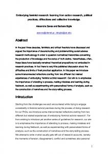
FIGURE 1 Indicator diagram
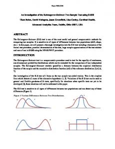
FIGURE 2 Solid-element finite element model of whole crankshaft
© SAE International
The load of connecting-rod bearing is calculated by the dynamic calculation method [20], which is obtained by analyzing the applied forces on the engine crank-rod mechanism based on the engine cylinder pressure indicator diagram (some shown in Figure 1) measured in the engine bench test and configuration parameters. The loads of all crankshaft main bearings are calculated by the finite element method of whole crankshaft solid-element [20]. The solid-element finite element model of whole crankshaft is shown in Figure 2. The loads of connecting-rod bearing and No.4 main bearing under full engine load at 1200 rpm and 3200 rpm are shown in Figures 3 and 4 respectively. There are great differences of the change rule and numerical value of the load of crankshaft bearing at corresponding moment in an engine operating cycle under different engine operating conditions. The maximum loads of connecting-rod bearing and all main bearings in an engine operating cycle under full engine load at 1200, 1600, 1800, 2000, 2200, 2400, 2800 and 3200 rpm are shown in Table 2. The maximum load of connecting-rod bearing in an engine operating cycle reduces with the increase of engine speed under same engine load. The maximum value of the maximum load of connecting-rod bearing in an engine operating cycle appears at low engine speed (1200 rpm), and the numerical value of the maximum load of connecting-rod bearing in an engine operating cycle at high engine speed (3200 rpm, rated engine operating condition) is small. The main reason is that the load of connecting-rod bearing is decided by the actual condition of the movement and applied force of engine crank-rod mechanism. The maximum load of connecting-rod bearing in an engine operating cycle appears near to the combustion top dead center. Based on the applied force analysis of engine crank-rod mechanism, the load of connecting-rod bearing is the resultant force of the forces
© SAE International
Calculation of the Loads of Crankshaft Bearing under Different Engine Operating Conditions
resulted from the cylinder pressure, the reciprocating inertial force and the rotational inertial force. The reciprocating inertial force and the rotational inertial force will be increased with the increase of engine speed, but the acting directions of the reciprocating inertial force and the rotational inertial force at the combustion top dead center are opposite to the direction of force resulted from the cylinder pressure, so the higher the engine speed the more the reduction of the maximum load of connecting-rod bearing. The change situation of the maximum © 2018 SAE International. All Rights Reserved.
Downloaded from SAE International by University of Leeds, Tuesday, August 28, 2018
RESEARCH ON THE LUBRICATION PERFORMANCE OF CRANKSHAFT BEARING
© SAE International
FIGURE 4 Load of No. 4 main bearing
© SAE International
FIGURE 3 Load of connecting-rod bearing
3
load of one crankshaft main bearing in an engine operating cycle against the engine speed is different from that of another crankshaft main bearing under same engine load. The loads of No.1 and No.5 main bearing are affected mainly by the force on single crank, and the maximum loads of No.1 and No.5 main bearing happen at the lower engine speed (1200 rpm). The loads of No. 2, No. 3 and No. 4 main bearing are decided by the forces of adjacent two cranks, and the maximum loads of No. 2, No. 3 and No. 4 main bearing happen at the higher engine speed.
The maximum loads of connecting-rod bearing and all main bearings in an engine operating cycle at 2200 rpm under 20%, 40%, 60%, 80% and full engine load are shown in Table 3. Under the same engine speed, the maximum loads of connecting-rod bearing and all main bearings in an engine operating cycle increase basically with the increase of engine load, and the maximum loads of connecting-rod bearing and all main bearings in an engine operating cycle take place at full engine load.
© SAE International
TABLE 2 Maximum loads of connecting-rod bearing and all main bearings at full engine load and different engine speed
Speed (rpm)
Connecting-rod bearing (N)
No. 1 main bearing (N)
No. 2 main bearing (N)
No. 3 main bearing (N)
No. 4 main bearing (N)
No. 5 main bearing (N)
1200
53331
20274
31468
25552
33835
18590
1600
51170
17201
28939
18793
30635
15926
1800
50427
19345
33061
20407
34978
17910
2000
46949
19203
33030
18699
34949
17772
2200
47620
19815
34587
17938
36581
18336
2400
47059
19605
35388
15776
36803
18131
2800
37376
15911
34085
24240
34355
14690
3200
27491
11903
29118
26126
29529
10882
© SAE International
TABLE 3 Maximum loads of connecting-rod bearing and all main bearings at 2200 rpm and different engine load
Load percentage (%)
Connecting-rod bearing (N)
No. 1 main bearing (N)
No. 2 main bearing (N)
No. 3 main bearing (N)
No. 4 main bearing (N)
No. 5 main bearing (N)
20
28691
12184
23992
11477
24135
11259
40
29087
12720
23306
16483
24858
11757
60
40858
17392
30918
14547
32491
16089
80
44273
18675
32765
16334
34650
17277
100
47620
19815
34587
17938
36581
18336
© 2018 SAE International. All Rights Reserved.
Downloaded from SAE International by University of Leeds, Tuesday, August 28, 2018
4
RESEARCH ON THE LUBRICATION PERFORMANCE OF CRANKSHAFT BEARING
Lubrication Analysis of Crankshaft Bearing under Different Engine Operating Condition Reynolds’ Equation The lubrication analysis of crankshaft bearing is based on the following Reynolds’ equation [21, 22]. ¶ æ 3 ¶p ö ¶h ö æ ¶h 2 ¶ æ 3 ¶p ö + 2Rb ÷ (1) ÷ = 6h Rb ç u çh ÷ + Rb ç h ¶q è ¶q ø ¶t ø ¶y è ¶y ø è ¶q
where p is the oil film pressure, h is the oil film thickness, η is dynamic viscosity of lubricating oil, u = uj + ub, uj is the velocity of journal surface and uj = Rjωj, Rj is the journal radius, ωj is the angular velocity of journal, ub is the velocity of bearing surface and ub = Rbωb, Rb is the bearing radius, ωb is the angular velocity of bearing, θ is the angular coordinate, y is the axial coordinate, t is the time. Oil Film Thickness The oil film thickness (not considering the surface deformation of bearing) is calculated by [23].
Fj =
L
2p
0
0
òò
æ h ¶p uh ö + ç ÷ Rjdq dy è 2 Rj¶q h ø
The frictional coefficient of journal surface μj is then given by
Formulation
Frictional Coefficient and Average Frictional Power Loss of Bearing The frictional force on the journal surface Fj can be calculated from
h = c + e cos (q -y ) (2)
where c is the radial clearance of bearing, e is the journal eccentric distance of bearing, ψ is the attitude angle of bearing.
mj =
Fj (5) F
The average frictional power loss of bearing in an engine operating cycle is then given by 720
wm =
å( F ) u / 720 (6) i =1
j i
Calculating Method Reynolds’ equation is solved by the finite difference method. The journal axis orbits of all crankshaft bearings are calculated by the dynamic method in the lubrication analyses of all crankshaft bearings [22].
FIGURE 5 Journal axis orbit of connecting-rod bearing
Load Equilibrium Equation If the effect of the oil film inertia is not considered, the motion of the journal axes of bearing conforms to the Newton second law, that is P + F = mj
dv (3) dt
where P is the load vector of bearing, F is the resultant oil film force vector of bearing, v is the velocity vector of journal axes. End Leakage Flow-Rate of Bearing The lubricating oil flow-rate Q1 from the front-end plane of bearing and the lubricating oil flow-rate Q2 from the rear-end plane of bearing are given by Q1 = -
ò
h3 ¶p × 12h ¶y
y =0
ò
h3 ¶p × 12h ¶y
y =L
0 2p
Q2 = -
0
× Rbdq × Rbdq
The total end leakage flow-rate Q of lubricating oil is then given by.
Q = Q1 + Q2 (4)
© SAE International
2p
© 2018 SAE International. All Rights Reserved.
Downloaded from SAE International by University of Leeds, Tuesday, August 28, 2018 RESEARCH ON THE LUBRICATION PERFORMANCE OF CRANKSHAFT BEARING
© SAE International
FIGURE 6 Journal axis orbit of No. 4 main bearing
5
FIGURE 7 Maximum oil film pressure of connecting-rod bearing
© SAE International
FIGURE 8 Maximum oil film pressure of No. 4 main bearing
The journal axes orbits, maximum oil film pressures, minimum oil film thicknesses, end leakage flow-rates and frictional coefficients of connecting-rod bearing and No. 4 main bearing in an engine operating cycle under full engine load at 1200 rpm and 3200 rpm are shown in Figures 5-14. Under different engine operating conditions, there are major differences of the lubrication performances of crankshaft bearings, and there are obvious differences in the changes and numerical values of the journal axes orbits, maximum oil film pressures, minimum oil film thicknesses, end leakage flowrates and frictional coefficients of crankshaft bearings in an engine operating cycle. The maximum oil film pressures, minimum oil film thicknesses and average frictional power losses of connecting-rod bearing and all main bearings in an engine operating cycle under full engine load and at 1200, 1600, 1800, 2000, 2200, 2400, 2800 and 3200 rpm respectively are shown in Tables 4-6. When the engine load is same, the maximum oil film pressure of connecting-rod bearing in an engine operating cycle is decreased generally with the increase of engine speed, and the maximum oil. film pressure (417.44 MPa) of connecting-rod bearing at 1200 rpm is as 3.41 times as that (122.39 MPa) at 3200 rpm, which shows that the maximum oil film pressure of connecting-rod bearing at lower engine speed is larger remarkably than the one at higher engine speed under the same engine load. The main reason is that, when the engine load is same, the maximum load of connecting-rod is © 2018 SAE International. All Rights Reserved.
© SAE International
Results and Discussion
decreased basically with the increase of engine speed, and the maximum load of connecting-rod at 1200 rpm is larger remarkably than the one at 3200 rpm. When the engine load is same, the changes of the maximum oil film pressures of all main bearings in an engine operating cycle is different one another with the change of engine speed. The maximum oil film pressures of No. 1 and
Downloaded from SAE International by University of Leeds, Tuesday, August 28, 2018 RESEARCH ON THE LUBRICATION PERFORMANCE OF CRANKSHAFT BEARING
FIGURE 9 Minimum oil film thickness of
FIGURE 11 End leakage flow-rate of connecting-rod bearing
© SAE International
connecting-rod bearing
FIGURE 10 Minimum oil film thickness of No. 4
© SAE International
6
FIGURE 12 End leakage flow-rate of No.4 main bearing
© SAE International
main bearing
© SAE International
© 2018 SAE International. All Rights Reserved.
Downloaded from SAE International by University of Leeds, Tuesday, August 28, 2018
RESEARCH ON THE LUBRICATION PERFORMANCE OF CRANKSHAFT BEARING
FIGURE 14 Frictional coefficient of No. 4 main bearing
© SAE International
© SAE International
FIGURE 13 Frictional coefficient of connecting-rod bearing
7
© SAE International
TABLE 4 Maximum film pressures of connecting-rod bearing and main bearings at full engine load and different engine speed
Speed (rpm)
Connecting-rod bearing (MPa)
No. 1 main bearing (MPa)
No. 2 main bearing (MPa)
No. 3 main bearing (MPa)
No. 4 main bearing (MPa)
No. 5 main bearing (MPa)
1200
417.44
64.42
95.83
99.95
103.72
44.23
1600
224.19
38.32
113.14
38.88
87.31
34.81
1800
158.46
39.36
88.13
36.97
93.05
35.84
2000
144.31
38.35
93.85
30.86
93.55
32.83
2200
144.47
38.52
95.88
33.79
97.55
33.31
2400
122.96
36.83
99.52
43.73
100.81
31.99
2800
140.38
40.50
76.84
139.86
71.81
40.52
3200
155.39
51.58
75.16
155.68
77.78
45.94
© SAE International
TABLE 5 Minimum film thicknesses of connecting-rod bearing and main bearings at full engine load and different engine speed
Speed (rpm)
Connecting-rod bearing (μm)
No. 1 main bearing (μm)
No. 2 main bearing (μm)
No. 3 main bearing (μm)
No. 4 main bearing (μm)
No. 5 main bearing (μm)
1200
2.16
4.22
2.99
4.19
2.93
4.86
1600
2.35
3.52
3.45
4.97
3.16
3.71
1800
2.96
3.09
3.26
4.17
3.07
3.27
2000
2.37
2.92
3.27
3.97
3.04
3.44
2200
2.05
2.54
3.19
3.36
2.93
3.27
2400
2.26
2.45
3.15
2.97
2.92
3.24
2800
2.29
2.48
4.37
1.02
3.21
3.51
3200
1.87
2.16
3.26
2.47
2.89
3.03
© 2018 SAE International. All Rights Reserved.
Downloaded from SAE International by University of Leeds, Tuesday, August 28, 2018 8
RESEARCH ON THE LUBRICATION PERFORMANCE OF CRANKSHAFT BEARING
TABLE 6 Average friction power losses of connecting-rod bearing and main bearings at full engine load and different
Speed (rpm)
Connecting-rod bearing (W)
No. 1 main bearing (W)
No. 2 main bearing (W)
No. 3 main bearing (W)
No. 4 main bearing (W)
No. 5 main bearing (W)
1200
39.96
54.33
47.71
53.87
49.02
55.25
1600
75.67
93.92
91.52
109.29
94.77
93.31
1800
94.94
110.99
109.64
140.86
124.35
113.09
2000
119.03
145.84
139.61
175.36
149.47
146.74
2200
138.16
170.13
181.48
210.88
192.71
176.52
2400
169.29
207.74
217.65
246.66
233.39
206.88
2800
139.26
284.17
243.16
426.14
279.66
231.72
3200
277.21
380.87
365.74
496.74
374.14
364.56
© SAE International
engine speed
Load percentage (%)
Connecting-rod bearing (MPa)
No. 1 main bearing (MPa)
No. 2 main bearing (MPa)
No. 3 main bearing (MPa)
No. 4 main bearing (MPa)
No. 5 main bearing (MPa)
20
71.95
21.67
65.99
38.97
64.77
19.35
40
69.49
22.06
59.98
46.94
65.67
19.35
60
109.85
31.39
84.86
34.17
87.04
28.02
80
121.66
34.71
91.07
33.49
92.56
30.81
100
144.47
38.52
95.88
33.79
97.55
33.34
© SAE International
TABLE 7 Maximum film pressures of connecting-rod bearing and main bearings at 2200 rpm and different engine load
Load percentage (%)
Connecting-rod bearing (μm)
No. 1 main bearing (μm)
No. 2 main bearing (μm)
No. 3 main bearing (μm)
No. 4 main bearing (μm)
No. 5 main bearing (μm)
20
2.81
2.84
3.53
3.37
3.43
3.52
40
2.77
2.76
3.65
3.15
3.48
3.55
60
2.58
2.74
3.31
3.31
3.03
3.35
80
2.55
2.78
3.25
3.38
3.02
3.48
100
2.05
2.54
3.19
3.36
2.93
3.27
No. 5 main bearings do not have obvious change at different engine speed, the maximum oil film pressures of No. 2 and No. 4 main bearings are larger at lower engine speed, and the maximum oil film pressure of No. 3 main bearings is larger at higher engine speed. When the engine load is same, the minimum oil film thicknesses of connecting-rod bearing and all main bearings in an engine operating cycle do not have the same change one another with the change of engine speed. The minimum oil film thicknesses of connecting-rod bearing and all main bearings in an engine operating cycle at higher engine speed are generally smaller in addition to the individual circumstances. When the engine load is same, the average frictional power losses of connecting-rod bearing and all main bearings increase with the increase of engine speed, and the average frictional power losses of connecting-rod bearing and all main bearings are the largest at higher engine speed (3200 rpm). The maximum oil film pressures, minimum oil film thicknesses and average frictional power losses of connectingrod bearing and all main bearings in an engine operating cycle at 2200 rpm under 20%, 40%, 60%, 80% and full engine load are shown in Tables 7-9.
When the engine speed is same, the maximum oil film pressures of connecting-rod bearing and all main bearings in an engine operating cycle are increased generally with the increase of engine load, but the maximum value of the maximum oil film pressures of No. 3 main bearing is appeared at the smaller engine load (40%). When the engine speed is same, the minimum oil film thickness of connecting-rod bearing is decreased with the increase of engine load, and the minimum value appears at the full engine load (100%). The minimum oil film thicknesses of all main bearings do not have the same change with the change of engine load, the minimum values of the minimum oil film thicknesses of No. 1, 2, 4, 5 main bearings all appear at the full engine load (100%), and the minimum values of the minimum oil film thicknesses of No. 3 main bearings appear at the smaller engine load. There is different behavior of oil film pressure and thickness at 40% engine load condition compared to other engine load conditions. The reason may be that the cylinder pressure at 40% engine load is similar to one at 20% engine load in the most times of an engine operating cycle, and the cylinder pressure at 40% engine load is smaller at some time. © 2018 SAE International. All Rights Reserved.
© SAE International
TABLE 8 Minimum film thicknesses of connecting-rod bearing and main bearings at 2200 rpm and different engine load
Downloaded from SAE International by University of Leeds, Tuesday, August 28, 2018
RESEARCH ON THE LUBRICATION PERFORMANCE OF CRANKSHAFT BEARING
9
© SAE International
TABLE 9 Average friction power losses of connecting-rod bearing and main bearings at 2200 rpm and different engine load
Load percentage (%)
Connecting-rod bearing (W)
No. 1 main bearing (W)
No. 2 main bearing (W)
No. 3 main bearing (W)
No. 4 main bearing (W)
No. 5 main bearing (W)
20
134.24
187.08
180.42
204.91
187.38
166.54
40
132.47
178.81
180.28
168.63
180.89
166.09
60
140.05
181.71
182.65
206.78
190.76
170.83
80
145.83
181.81
182.28
209.29
193.62
171.72
100
138.16
170.13
181.48
210.88
192.71
176.52
When the engine speed is same, the average frictional power losses of connecting-rod bearing and all main bearings in an engine operating cycle do not change obviously with the change of engine load. The average frictional power losses of connecting-rod bearing and all main bearings in an engine operating cycle are generally increased slightly with the increase of engine load in addition to the individual engine loads. In addition, the corresponding comparisons between the lubrication performance of connecting-rod bearing and the one of main bearings at same engine operating condition (shown in Tables 4-9) show that, the maximum oil film pressure of connecting-rod bearing in an engine operating cycle is larger than those of all main bearings, the minimum oil film thickness of connecting-rod bearing in an engine operating cycle is smaller than those of all main bearings, and the average frictional power losses of connecting-rod bearing in an engine operating cycle is smaller than those of all main bearings. Also, there is the corresponding difference between the lubrication performances (the maximum oil film pressure, minimum oil film thickness and average frictional power loss in an engine operating cycle) of all main bearings one another at same engine operating condition, and some difference is larger.
Conclusions 1. Under different engine operating conditions, there are great differences about the change and the numerical value at corresponding moment of the loads of crankshaft bearings in an engine operating cycle. 2. Under different engine operating conditions, there are obvious difference in the change and numerical value of the journal axes orbit, maximum oil film pressure, minimum oil film thickness, end leakage flow-rate and frictional coefficient of crankshaft bearing in an engine operating cycle. 3. Under the same engine operating condition, the maximum oil film pressure of connecting-rod bearing in an engine operating cycle is larger than the one of main bearing; the minimum oil film thickness of connecting-rod bearing in an engine operating cycle is smaller than the one of main bearing; the average frictional power loss of connecting-rod bearing in an engine operating cycle is smaller than the one of main bearings. © 2018 SAE International. All Rights Reserved.
4. There are the larger difference between the lubrication performances of main bearings one another under same engine operating condition. In conclusion, there are the major difference in the changes and numerical values of the lubrication performances of connecting-rod bearing and main bearings under different operating conditions. The most unfavorable case of the lubrication performance of crankshaft bearing may not take place in rated engine operating condition. There are the major difference between the lubrication performance of connectingrod bearing and the one of main bearings, and there are the major difference between the lubrication performances of main bearings one another under same engine operating condition. Therefore, it is not comprehensive and reasonable that only the lubrication performance of a certain crankshaft bearing (connecting-rod bearing or one main bearing) at rated engine operating condition is analyzed in the design of engine crankshaft bearing. It is necessary to analyze simultaneously the lubrication performances of all crankshaft bearings (connecting-rod bearing and all main bearings) under different engine operating conditions based on considering the actual structure, movement and applied force condition of engine crank-rod mechanism. In this paper, the lubrication analysis of crankshaft bearing is considered in a pure hydrodynamic lubrication regime. In order to make the results close the actual situation more, the surface roughness, deformation, mechanical properties of bearing and temperature, etc. will be considered in the further research.
References 1. Singh, D.V., Sinhasan, R., and Pal, R., “Performance Characteristics of an Ungrooved Big-End Bearing with Misalignment,” Tribology Transactions 32:234-238, 1989. 2. Paranjpe, R.S. and Goenka, P.K., “Analysis of Crankshaft Bearings Using a Mass Conserving Algorithm,” Tribology Transactions 33:333-344, 1990. 3. Aitken, M.B. and McCallion, H., “Elastohydrodynamie Lubrication of Big-End Bearings Part 2 Ratification,” Proc IMechE Part C: Journal of Mechanical Engineering Science 205:107-119, 1991. 4. Vijayaraghavan, D., Brewe, D.E., and Keith, T.G., “Effect of Out-Of-Roundness on the Performance of a Diesel Engine Connecting-Rod Bearing,” ASME Journal of Tribology 115:538-543, 1993.
Downloaded from SAE International by University of Leeds, Tuesday, August 28, 2018
10
RESEARCH ON THE LUBRICATION PERFORMANCE OF CRANKSHAFT BEARING
5. Bonneau, D., Guines, D., and Frêne, J., "EHD Analysis, Including Structural EHD Analysis, Including Structural Inertia Effects and a Mass-Conserving Cavitation Model," ASME Journal of Tribology 117: 540-547, 1995.
20. Sun, J., Wang, J., and Gui, C., “Whole Crankshaft BeamElement Finite-Element Method for Calculating Crankshaft Deformation and Bearing Load of an Engine,” Proc IMechE Part J: Journal of Engineering Tribology 224:299-303, 2009.
6. Paranjpe, R.S., “A Study of Dynamically Loaded Engine Bearings Using a Transient Thermohydrodynamic Analysis,” Tribology Transactions 39(3):636-644, 1996.
21. Stachowiak, G.W. and Batchelor, A.W., “Engineering Tribology,” (Burlington, Elsevier ButterworthHeinemann, 2005).
7. Xu, H. and Crooks, C.S., “A Study of the Behavior of Connecting Rod Bearings Using an EHL Predictive Tool,” SAE Technical Paper 970217, 1997, doi:10.4271/970217.
22. Hamrock, B.J., Schmid, S.R., and Jacobson, B., “Fundamentals of Fluid Film Lubrication, Second Edition,” (New York, Mercel Dekker Inc., 2004).
8. Thierry, G., Dominique, B., and Christian, G., “ThreeDimensional EHD Behavior of the Engine Block/Crankshaft Assembly for a four Cylinder Inline Automotive Engine,” ASME Journal of Tribology 121(4):721-730, 1999.
23. Sun, J., Zhao, X.Y., and Wang, H., “Lubrication Analysis of Crankshaft Bearing Considering Crankshaft Deformation,” SAE Technical Paper 2011-01-0613, 2011, doi:10.4271/201101-0613.
9. Piffeteau, S., Souchet, D., and Bonneau, D., “Influence of Thermal and Elastic Deformations on Connecting-Rod Big End Bearing Lubrication under Dynamic Loading,” ASME Journal of Tribology 122:181-191, 2000.
Contact Information
10. Mourelatos, Z.P., “An Efficient Journal Bearing Lubrication Analysis for Engine Crankshafts,” Tribology Transactions 44:351-358, 2001. 11. Mustapha, L., Djamel, F., and Daniel, N., “The Effect of Misalignment on Performance Characteristics of Engine Main Crankshaft Bearings,” European Journal of Mechanics A/Solids 21:703-714, 2002. 12. Souchet, D., Hoang, L.V., and Bonneau, D., “Thermoelastohydrodynamic Lubrication for the Connecting Rod Big-End Bearing under Dynamic Loading,” Proc IMechE Part J: Journal of Engineering Tribology 218:451464, 2004. 13. Bukovnik, S., Dörr, N., Caika, V. et al., “Analysis of Diverse Simulation Models for Combustion Engine Journal Bearings and the Influence of Oil Condition,” Tribology International 39:820-826, 2006. 14. Tabrizi, A.A. and Kakaei, A.H., “Different Simulation Models of Connecting Rod Hydrodynamic Bearing,” SAE Technical Paper 2009-01-1863, 2009, doi:10.4271/2009-011863. 15. Choi, J., Kim, S.S., Rhim, S.S., and Choi, J.H., “Numerical Modeling of Journal Bearing Considering Both Elastohydrodynamic Lubrication and Multi-Flexible-Body Dynamics,” International Journal of Automotive Technology 13(2):255-261, 2012. 16. Singh, H. and Sen, S.S., “Wear in Hydrodynamic Journal Bearings: A Review,” International Journal of Modern Engineering Research 4(8):45-57, 2014. 17. Farfan-Cabrera, L.I. and Gallardo-Hernandez, E.A., “Wear Evaluation of Journal Bearings Using an Adapted MicroScale Abrasion Tester,” Wear 376-377:1841-1848, 2017. 18. Vencl, A. and Rac, A., “Diesel Engine Crankshaft Journal Bearings Failures: Case Study,” Engineering Failure Analysis 44:217-228, 2014. 19. Choi, J., Kim, S.S., Rhim, S.S., and Choi, J.H., “Numerical Modeling of Journal Bearing Considering both Elastohydrodynamic Lubrication and Multi-Flexible-Body Dynamics,” International Journal of Automotive Technology 13(2):255-261, 2012.
Jun Sun School of Automotive and Transportation Engineering Hefei University of Technology 193 Tun Xi Road Hefei 230009 China
[email protected] Phone: +86-551-2901727-8209
Acknowledgements The authors would like to express their gratitude to the Science Fund of State Fey Laboratory of Engine Reliability (skler-201708) and National Natural Science Foundation of China (51490660/51490661) for the financial support to this paper.
Definitions F - resultant oil film force vector of bearing Fj - frictional force on the journal surface P - load vector of bearing Q - total end leakage flow-rate of the lubricating oil Q1 - lubricating oil f low-rate from the front-end plane of bearing Q2 - lubricating oil flow-rate from the rear-end plane of bearing Rb - bearing radius Rj - journal radius c - radial clearance of bearing e - journal eccentric distance of bearing h - oil film thickness p - oil film pressure t - time ub - velocity of bearing surface uj - velocity of journal surface
© 2018 SAE International. All Rights Reserved.
Downloaded from SAE International by University of Leeds, Tuesday, August 28, 2018
RESEARCH ON THE LUBRICATION PERFORMANCE OF CRANKSHAFT BEARING
v - velocity vector of journal axes w m - average frictional power loss of bearing in an engine operating cycle y - axial coordinate η - dynamic viscosity of lubricating oil
11
θ - angular coordinate μj - frictional coefficient of the journal surface ψ - attitude angle of bearing ωb - angular velocity of bearing ωj - angular velocity of journal
All rights reserved. No part of this publication may be reproduced, stored in a retrieval system, or transmitted, in any form or by any means, electronic, mechanical, photocopying, recording, or otherwise, without the prior written permission of the copyright holder. Positions and opinions advanced in this paper are those of the author(s) and not necessarily those of SAE International. The author is solely responsible for the content of the paper. ISSN 0148-7191