Abstracting Business Level UML Diagrams from Web Applications Giuseppe Antonio Di Lucca*, Anna Rita Fasolino°, Porfirio Tramontana°, Ugo De Carlini°
[email protected],
[email protected],
[email protected],
[email protected]
*RCOST - Research Centre on Software Technology, University of Sannio Palazzo ex Poste, via Traiano, 82100 Benevento, Italy ° Dipartimento di Informatica e Sistemistica, Università di Napoli Federico II Via Claudio, 21, 80125 Napoli, Italy Abstract In this paper a reverse engineering approach for reconstructing UML diagrams at business level of the application domain of a Web Application is presented. In particular the approach allows the reconstruction of the UML class diagram providing an object-oriented conceptual model of the application domain, sequence diagrams modeling the interactions among the identified business objects and use case diagrams modeling the user functionalities provided by the Web Application. Heuristic criteria exploiting source code analysis are used for recovering the diagrams. Tools for implementing these criteria have been produced, and experiments for validating them have been carried out with the support of case studies. Experimental results showed the feasibility and the effectiveness of the proposed approach. Keywords: Reverse Engineering, Web Engineering, Object Orientation
1. Introduction The rapid and progressive diffusion of the Internet in the modern society has triggered a growing request for Web Applications implementing more and more complex functionality and strict quality requirements. In this rapidly evolving context, developers usually build Web Applications under the pressure of a short time-to-market and an extremely high competition. Although several development methodologies are being proposed in the literature for building a Web Application (WA) [11, 12, 17, 18, 4], good software engineering principles usually are not applied in the practice. Indeed, most Web technologies actually encourage bad, rather than good practices, and the application of the software engineering principles of modularity, data encapsulation, separation of concerns, or information hiding is actually not well supported by HTML, XML, and scripting languages (such as Javascript, JSP, VBScript, PHP) widely used in current WA implementations. Because of the development problems and the limitations of current Web technologies, maintaining an existing WA is not a straightforward task. Reverse engineering techniques and tools
have proved useful to support the comprehension and maintenance of large-scale traditional applications. The research community is now addressing the problem of defining and validating similar approaches for reverse engineering existing WAs. Recently, a number of approaches for reverse engineering WAs have been proposed in the literature. Some of them aim at obtaining an architectural view of the WA that depicts WA components (i.e., pages, or inner page components) and their relationships at different degrees of detail [2, 6, 16]. Some other approaches exploit clustering techniques for abstracting a description of the functional requirements implemented by the WA, which is cast into UML use case diagrams [7]. However, in some maintenance processes, neither the architectural view nor the functional one of an existing application may suffice to support the software engineer tasks. In some cases, indeed, conceptual models describing the domain of the application provide precious information to be exploited during maintenance or testing activities. Examples of these conceptual models include object oriented models at business level, describing the domain of the application in terms of business objects and logical relationships between them, as well as models representing the behavior and the dynamic of these objects. For instance, business level object oriented models extracted from procedural legacy systems have been used to migrate the systems towards object-oriented platforms with the support of wrapping technologies [5]. Moreover, objects from an objectoriented conceptual model have proved useful to support a systematic reuse, since each validated object represents a reusable component that can be integrated in the production of new systems [1]. In the literature, several reverse engineering methods have been proposed for recovering objects and object oriented models from traditional software [1, 3, 9, 10, 13, 14, 15, 19]. Defining and validating similar approaches in the context of Web applications represent a relevant research issue. In this paper, the problem of reverse engineering Web Applications with the aim of recovering conceptual models describing the applications at the business level will be addressed.
Proceedings of the Fifth IEEE International Workshop on Web Site Evolution (WSE’03) 0-7695-2016-2/03 $17.00 © 2003 IEEE
Reverse engineering techniques exploiting heuristic criteria will be proposed for obtaining object oriented conceptual models, including class diagrams, use case diagrams, and sequence diagrams at business level. The UML notation will be used for representing these models. Tools for implementing the proposed techniques have been produced, and experiments for validating them have been carried out with the support of case studies. Experimental results showed the feasibility and the effectiveness of the proposed approaches. The paper is structured as follows: in Section 2 the approach for reconstructing a business class diagram from the code of an existing WA is presented, while Section 3 describes the techniques for obtaining use case diagrams, and sequence diagrams associated with business classes. In Section 4, a case study selected from the experiments carried out for validating the proposed approach is described. Conclusive remarks are, finally, provided in Section 5.
2. Recovering a Class Diagram at Business Level Given a Web application, the class diagram at business level will describe the relevant conceptual components (business objects) from the domain of the problem addressed by the WA and their mutual relationships. This model can be used for documenting an existing undocumented, or poor documented WA, as well as it provides a valid tool for redesigning, reengineering, or migrating an existing application towards a different technological platform. According to approaches proposed in the context of traditional software [5, 6], a business level class diagram can be recovered from the code of an existing WA by a reverse engineering process including three main steps: -
Identification of candidate classes and their attributes; Association of methods to candidate classes; Identification of relationships between classes.
In the following we will use the terms class and object as synonyms. In traditional software, the identification of the candidate objects and of their attributes is made by looking for groups of logically related data making up the state of objects. This search is usually based on those language mechanisms that allow groups of related data implementing a relevant concept, either from the domain of the application or from domain of the solution, to be defined in the code. These mechanisms include those for the definition and use of data structures such as records, user data types, and table schemas in databases. Moreover, the identification of object operations, i.e., methods, is centered on suitable pieces of code (such as programs, subroutines, slices) that can be associated with the candidate objects according to specific coupling criteria. Finally, specific heuristic criteria, such as those defined in [6], can be used to define the relationships between
objects. Several questions have to be addressed when trying to port these methods to the WA context. The first problem regards the identification of objects and objects’ attributes in a WA, since the selection of the mechanisms that are generally used for implementing groups of related data is not obvious for WAs. Most web technologies and languages (such as HTML, ASP, PHP, VBS, JSP, etc.) provide syntactic constructs for declaring data groups like RecordSets, or Collections, or Classes, but some of them are not used frequently. Moreover, since a WA is usually implemented as a multi-tier system, with a database server implementing one tier of the architecture, a simple WA code analysis may not allow the identification of the persistent data stores and of the data store schemas. In this case, indeed, such data store descriptions may be deployed on a different tier of the application, and may be inaccessible, such as in the case of a WA that makes the services of an existing information system available on the net, implementing the frontend of the system. A second question with WAs regards the identification of the chunks of code implementing the object methods, since the pieces of code that are usually considered for traditional software (e.g., programs, subroutines, slices, etc.) may not be meaningful for WAs. In this case, possible functional units to be considered should include web pages, script blocks inside a page, functions in a page, depending on the requested degree of granularity. Moreover, appropriate criteria for electing these chunks of code to object methods and associating them with the correct object should be accurately defined, as well as suitable rules for defining the possible relationships between the recovered objects should be defined. In the following subsections, an approach to overcome these problems is proposed.
2.1 Identifying candidate classes and their attributes The approach we propose for identifying candidate classes from a WA includes two steps. The first step comprises the identification of relevant groups of data items from the WA code; in the second step, an automatic procedure is executed to define the candidate classes from the list of groups identified in the previous step. The elements of interest for identifiying the attributes of candidate classes in a WA will be groups of data items that are involved in the same user input/output operation (such as data displayed in input/output HTML forms, or HTML tables), or in the same read/write operation on a data store (such as an ASP Recordset, or an array of heterogeneous data in PhP language), or the data set involved in a database query operation. In addition, data groups that are passed throw distinct pages or instances of Classes used in the pages will be taken into account. The rationale behind this choice is that the set of data items that a user inputs by an input form, or that are shown to a user by an
Proceedings of the Fifth IEEE International Workshop on Web Site Evolution (WSE’03) 0-7695-2016-2/03 $17.00 © 2003 IEEE
output form, usually represents the concepts of interest for the user in the domain of the application. Analogously, data items that are read from, or written to a persistent data store may be representative of meaningful concepts of the business domain. In a preliminary step of the process, a static analysis of the WA source code will be required for retrieving these data groups and their references in the code. Each data item of each group will be associated with the identifier used to reference it in the code. Therefore, the items from the groups will be submitted to a refinement step aiming at solving the problems of synonyms (i.e., identifiers with different names but the same meaning) and homonyms (i.e., identifiers with the same names but different meanings). Synonym identifiers must be assigned with the same unique identifier. Homonym identifiers must be associated with distinct names. In addition, while carrying out synonyms & homonyms analysis a meaningful name, synthesizing the meaning of the data according to the rules of the business domain, is assigned to each data item. Of course, both the definition of the names, and synonyms and homonyms analysis are based on code reading and inspection of available documentation and are human intensive tasks. At this point, each data group may be considered as the attributes of a potential class and a validation should be carried out for distinguishing valid business classes, i.e. classes actually associated with a concept from the business domain, from invalid ones. This validation is usually accomplished manually. In order to reduce the effort required by this analysis, our approach exploits an automatic procedure that analyzes the data groups in order to identify the ones that are more likely to represent meaningful classes. Only the selected data groups are, therefore, submitted to the validation process. This procedure, called Produce_Candidate_Objects, is based on heuristic criteria and is illustrated in Figure 1, where: − − − − − − − −
GList is the list of data groups; g is the generic group in the GList; Card(g) is the cardinality of the g group; Nref(g) is the number of references to the g group; a is a generic data item in g; CAND is the list of candidate objects; C is a generic candidate object from CAND; SORT (A, K) is a function for sorting the list A according to the criteria described in K; − TOP(A) is a function for accessing the top element of a list A; − REMOVE(A, x) is a procedure for removing an item x from the list A; − INSERT(A, x) is a procedure for inserting the item x in the list A; − ADD(C, h) is the procedure for adding all the item of a group h in the C group. The procedure Produce_Candidate_Objects analyzes the input list Glist of data groups and produces the output list CAND of candidate classes.
The first heuristic rule implemented by this procedure states that the more the references of a same data group in the code, the greater the likelihood that it represents a meaningful concept. The second heuristic rule establishes that groups with a small size may represent more simple and atomic concepts than larger groups, and larger groups may represent more complex concepts made up of joined smaller groups. According to these two rules, groups from the Glist are preliminarily arranged in descending order with the number of references of each g group, and in ascending order with the cardinality of each group. This order is produced by the procedure SORT whose output consists of the ordered list ‘OrdList’ of data groups. Procedure Produce_Candidate_Objects (in: GList; out: CAND); BEGIN OrdList = SORT (Glist, Descending on Nref(g)AND Ascending on Card(g) ); CAND = ∅; WHILE (OrdList ≠ ∅ OR (∪i a ∈ Ci ≡ ∪i a ∈ gi ))DO h=TOP(OrdList); IF (∃ a∈h: a∉C ∀ C ∈CAND) THEN IF (!∃ C∈CAND: C ⊆ h THEN INSERT(CAND, h) ELSE ∀ Ci ∈ CAND: Ci ⊆ h DO BEGIN k = h - ∪i Ci; ADD(C, k); END END IF END IF REMOVE (OrdList, g); END WHILE END
Figure 1: The procedure generating the list of candidate objects Starting from the top group in OrdList, the procedure analyzes each group and, if a group comprises at least a new data item not yet included in any other group in CAND, it will be inserted in the CAND list of candidate objects. OrdList is examined until it includes at least a group, or until the union set of all the data items of the candidate objects in CAND and the union set of all the data items of the groups in Glist are equal. When a group h from OrdList includes all the data items making up one or more groups Ci in CAND, only the k data items in h that are not yet included in any group of CAND are added to the Ci groups whose elements are all included in h. The reason is that the group h is likely to represent a composite concept produced by a logical link among the Ci groups. The attributes that are added to the Ci groups are necessary to record this link,
Proceedings of the Fifth IEEE International Workshop on Web Site Evolution (WSE’03) 0-7695-2016-2/03 $17.00 © 2003 IEEE
which will be used to deduce relationships between objects, according to the method proposed in Section 2.3. As an example of this case we may consider a data group associated with a report showing information about some distinct objects of the application domain. At the end of the procedure, the CAND list will include the set of data groups that have been selected as candidate objects. Each group in the CAND list will have to be assigned with a meaningful name describing the concept it represents. The data items of each group will make up the attributes of the object, e.g., its state. The attributes that appear in more than one candidate object will be analyzed in a successive step according to the approach presented in the next Section 2.3. For the sake of precision, CAND is the set of candidate classes from which business objects can be instantiated. As an example of the application of the proposed method, if we have the following OrdList:
Therefore, minimization of the coupling between objects is achieved by associating each page to the object it is most highly coupled with. In particular, if a page accesses exclusively one object, it will be assigned as a method of that object. If a page accesses more objects, it will be assigned to the object it accesses prevalently. In this second case, the accesses of the page to the other objects can be considered as messages exchanged from the object the page has been assigned with, to the other objects. To implement the criterion for associating pages to objects, we introduce the following definitions: − − − −
OrdList = {G1=(a,b,c), G2=(d,e,f), G3=(a,b,c,d,e,f,g), G4=(a,b,c,m,n), G5=(a,b,q,r), G6=(d,f,s,t,u)} The final CAND list will contain the following groups of candidate business objects: CAND = {(G1,m,n,g), (G2,g), G5, G6}.
2.2 Associating methods to classes The identification of methods to be associated with classes essentially depends on two factors: the degree of granularity of the chunks of code to be considered as potential methods, and the definition of a criterion for assigning a potential method to a class. In a WA the search for class methods can be centered on chunks of code with fine granularity levels, such as inner page components like scripts or modules included in pages, or on coarse-grained components, like pages or groups of pages. Finer the granularity level, greater will be the effort required for extracting the component from the code, and reengineering it as an object method. Our approach proposes to consider physical Web pages (e.g., Server pages, Client pages) as potential methods to be associated with the candidate objects of the WA, rather than inner page components. This choice allows a reduction of the effort required for the object oriented reengineering of the WA. As to the problem of defining a criterion for associating methods to objects, an approach that aims to minimize the coupling between distinct objects will be adopted. Measures of coupling between pages and objects are computed based on the accesses of pages to the candidate object. A page accesses a candidate object when it includes instructions that define or use the value of some object attribute. We assume that accesses made to define the value of some object attribute produces a greater coupling than accesses made to use some object attribute.
− − −
M={mi}, is the set of pages (e.g., potential object methods in the following we will use the terms page and method as synonyms); c is the generic element from the CAND list of candidate objects; αdef is a positive number expressing a weight associated with each define access made to an object; αuse is a positive number expressing a weight associated with each use access made to an object; αdef > αuse ; Ndef,m,c is the number of accesses of type define made by a page m to the object c; Nuse,m,c is the number of accesses of type use made by a page m to the object c.
Moreover, we define the function Acc(m, c) that expresses the weighted number of accesses made by m to c: Acc (m, c)= αdef * Ndef,m,c + αuse * Nuse,m,c
(1)
Said MAX [X] a function that returns the maximum value from a set X of values, the following criterion will be used to assign a method m to a class c: m is assigned to c ∈ CAND ⇔ Acc(m , c) = MAX cj ∈ CAND [Acc(m , cj)]
(2)
that is, the page m will be assigned, as a method, to the class c iff c is the class such that the number of weighted accesses made by the page m to c is greater than all the other weighted accesses m makes to other classes. When the criterion (2) is satisfied by two or more classes, the intervention of a software engineer will be required to establish the correct assignment of m with one of the classes. Pages that do not make access to any objects will be considered as coordinating modules controlling the executions of other methods (in a WA this page usually corresponds to home pages, or pages that address the user navigation along the WA).
2.3 Identifying relationships between classes The candidate classes in the CAND list may include common attributes: these attributes will indicate potential relationships among the involved classes. These relationships will be depicted as UML association relationships. For each set of classes having common attributes, a UML association is established between them. Each common attribute
Proceedings of the Fifth IEEE International Workshop on Web Site Evolution (WSE’03) 0-7695-2016-2/03 $17.00 © 2003 IEEE
will be assigned just to one class of the set, and all these classes will be linked by an association relationship. The software engineer intervention will be required to establish the correct assignment of the attributes to the object. The case of pages accessing more than one class will originate additional relationships. More precisely, the accessing page will be assigned with the object it is most highly coupled with, according to the criterion (2), while a relationship will be defined between the class the page is assigned to, and each remaining class the page accesses. Also this kind of relationships will be depicted as UML association relationships. In a successive refinement step, the recovered association relationships may be analyzed in order to assess whether they can be substituted by a class with specialization or any aggregation/composition relationship. Finally, a UML Class diagram will represent the recovered classes, their attributes and methods, and the relationships among them.
3. Recovering UML Use Case and Sequence diagrams In this section, the reverse engineering approaches proposed for recovering use cases and sequence diagrams from the code of a WA will be presented.
3.1 Recovering Use Case Diagrams The problem of recovering use cases from the source code of a WA has been already addressed in [7, 8]. In those papers, an automatic clustering approach is proposed, in order to group Web pages of a WA into meaningful (highly cohesive) and independent (loosely coupled) clusters. The clustering approach evaluates the degree of coupling between interconnected pages depending on both the typology and the topology of the connections, and proposes a clustering configuration that includes clusters with high intra-connectivity and low inter-connectivity. The clustering configuration is submitted to a validation and a concept assignment process in order to identify the user functionality each cluster is responsible for. Groups of validated clusters can be associated with potential use cases of the WA, and a use case model can be reconstructed for describing the external behavior offered by the application to the end users. In order to obtain a Use Case Diagram, relationships among use cases may be deduced analyzing the links between corresponding clusters. As an example, if a cluster associated with a use case ‘A’ is linked to just another cluster associated with the use case ‘B’, a candidate relationship from use case ‘A’ to use case ‘B’ may be proposed; if a cluster is linked to more other clusters, a possible relationship among the use case corresponding to the former cluster and the remaining ones may have to be considered. However, these indications provide the reverse engineer just with simple suggestions about how use case diagrams can be drawn. Finally, actors in the Use Case
diagram will be linked to use cases associated to clusters including any page requiring data input from a user (e.g., Web pages including forms), or database connections.
3.2 Recovering Sequence Diagrams As to the UML Sequence diagrams abstraction, for each use case (i.e., validated cluster) it is possible to produce a Sequence Diagram whose objects will derive from classes associated with cluster’s pages, while interactions among objects will be deduced from the accesses that a page assigned as a method to a given Class makes to other Classes. The recovering of a sequence diagram is obtained by a process, based on heuristic criteria, that includes the following steps: − draw a sequence diagram for each identified use case; − identify the pages composing the cluster (or group of clusters) associated to a use case; − for each page in the cluster, identify the class which the page was assigned to as a method: for each identified class put an object in the diagram; − if a page assigned to an object of the Class A makes accesses to other objects of the Classes Bi, draw an interaction between the object of A and each object of Bi; − assign each interaction with a meaningful name (corresponding to the name of the invoked method) and define the list of parameters exchanged between the objects (deduced by analysing the data flow between the Web application interconnected items); − draw an interaction between an object and an actor if that object was assigned to a page including input or output forms; − if there is a relation between pages assigned to the same class, it will be considered as a call between methods of the same Class, and therefore a 'Message to self' will be drawn on the object life-line. According to the UML notation, in a Sequence Diagram the correct temporal sequence of the events (e.g., interactions between objects) can be deduced by reading the flow of interactions from upside to downside in the diagram. In the recovered Sequence Diagrams, this temporal sequence may be reconstructed by statically analysing the control flow in the source code. As a preliminary result, the temporal sequence may correspond to the lexicographic statement sequence. Therefore, dynamic analysis can be used to refine the statically defined temporal sequence.
4. A case study In order to assess the effectiveness of the proposed approaches, several controlled experiments were carried out involving some real-world Web applications. An example of these experiments is shown in this section, where the results obtained in a case study are presented and discussed. In the case study, a Web application designed to support the activities of undergraduate courses offered by a Computer Science
Proceedings of the Fifth IEEE International Workshop on Web Site Evolution (WSE’03) 0-7695-2016-2/03 $17.00 © 2003 IEEE
Department was taken into account, and the approach was used to reconstruct the business model of this application. The final model was validated by submitting it to the judgment of the software engineers that had produced the application. Just the source code of the WA was used during the experiment, and no documentation was provided to the experimenters that carried out it. The application had been implemented using HTML, ASP, VBScript and Javascript technologies, with a MsAccess database, and was composed of 107 source files organized in one directory. The application included 75 server pages, 23 client pages and one utility module. Altogether, the size of the application was of 7,648 LOCs. During the first step of the recovery process, the code was analyzed for identifying data groups, according to the approach presented in Section 2.1. Groups of data items involved in I/O forms, in read/write operations on persistent data stores, and so on, were looked for, and the number of their occurrences in the code was evaluated. The WARE tool [6], that statically analyzes the source code of WAs, was used to support this task. The analysis retrieved 128 references to data groups including a total of 485 data items. Therefore, synonyms/homonyms analysis was carried out and each data item was assigned with a meaningful name. This task was accomplished by reading and inspecting the code, and analyzing the WA during its execution. At the end of synonyms/homonyms analysis, just 43 different data groups including a total of 26 different data items were defined. These data groups were submitted to the candidature procedure Produce_Candidate_Objects that automatically selected 8 candidate classes, including a total of 38 attributes (of course just 26 were different attributes). The candidate classes are listed in Table 1, where the set of attributes of each class is reported. Some candidate classes presented common attributes that were exploited to identify the relationships among the classes in the third step of the process. In the second step of the process, the accesses each page made to the candidate classes were analyzed. Twenty pages that did not reference any data group were detected, since they had only presentational or navigational purposes. The remaining pages were assigned as methods of the candidate classes according to the approach described in section 2.2. More precisely, for each page the function Acc(m,c) was computed with respect to all the accesses to all the classes the page made, and each page was assigned to a class according to the criterion (2) in section 2.2. For evaluating the function Acc(m,c), different values had to be defined for the αDEF and αUSE weights. During the experiments carried out with different WAs, several values for αDEF and αUSE were tried in order to detect the ones that produced the best results (i.e., the best assignment of methods to classes, according to the judgment of an expert). The best results were achieved for αDEF = 1 and αUSE = 0.6, and this couple of values were used in the case
study too. Candidate classes and corresponding attributes Student Teacher
Exam Session Tutoring
(Student name, Student surname, Student code, Student email, Student phone number, Student password) (Teacher name, Teacher surname, Teacher email, Teacher phone number, Teacher password, Teacher code) (Exam date, Exam time, Exam classroom)
(Tutoring date, Tutoring start time, Tutoring end time, Course code, Course name) Course (Course code, Course name, Course academic year) Tutoring (Student name, Student surname, Student code, Request Tutoring request date) News (Course code, News text, News number, News date, Teacher code) Exam (Student code, Student name, Student surname, Course Reservation code, Exam date, Exam reservation date)
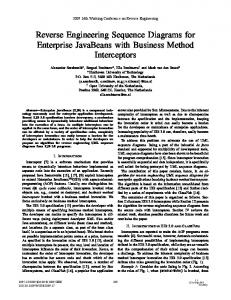
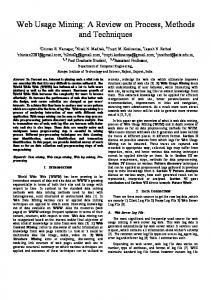
Table 1: Candidate classes produced by the Candidature Procedure In the third step of the process, associations between classes had to be defined. In a preliminary phase, candidate classes were examined in order to find classes with common attributes. This task was carried out with the support of an automatic procedure. For each set of classes including a same attribute, an association between these classes was established, and each common attribute was assigned to the class that was better characterized by that attribute, depending on the experimenter’s judgment. Other relationships between classes were defined on the basis of accesses to the attributes of other classes that were made by a method assigned to a given class. A relationship was established between the class the method was assigned to, and the remaining classes whose attributes were referenced by this method. Figure 2 shows the UML class diagram representing the resulting business object model of the WA, while Table 2 reports the list of the WA pages assigned as methods to each identified class. In order to abstract the use cases of the application, the clustering approach proposed in [7] was applied. As a result of the automatic clustering, 44 valid clusters were recovered that were submitted to a validation step. The validated clusters were initially associated to use cases and a top use case diagram was produced. Figure 3 reports an excerpt of this diagram, showing the and relationships between use cases that have been deduced using the criteria proposed in Section 3.1. For each of these use cases, a Sequence Diagram was drawn. As an example of these diagrams, Figure 4 reports the one derived for the use case ‘Course insertion’, that inserts in the database a new Course taught by a given teacher. The cluster corresponding to this use case includes two pages: the client page ‘aggiungicorso.html’ and the server page ‘aggiungicorso.asp’, both assigned to the object Course. The former page includes a form requiring input of data by a user, therefore an interaction of
Proceedings of the Fifth IEEE International Workshop on Web Site Evolution (WSE’03) 0-7695-2016-2/03 $17.00 © 2003 IEEE
this page with an actor was drawn. The page ‘aggiungicorso.html’ does not refer to any other object, but is linked to the page ‘aggiungicorso.asp’ by a submit operation: this was modeled in the sequence diagram by the self-interactions on the Course object. The page ‘aggiungicorso.asp’ makes a reference to some attributes of the object Teacher, then an interaction between the Course and Teacher object was also drawn.
:Course
Teacher
Input course data (course code, name, academic year)
:Teacher
Insert new Course Get teacher code
Insertion OK
Figure 4: The UML sequence diagram representing the interactions for the use case ‘Course insertion’ Student Name Surname E-mail Password Code Phone number
Class
chiediPass.html, cancellareg1.asp, cancellareg2.asp, visualizzareg2.asp, prenotatiapp3.asp, FormCancPreRicevimento.asp, PreRicev3.asp, iscrivicorsi.asp, regstudente.asp, regstudente.html, autenticazionestudente.asp, checkStudente.asp, modificaiscriz2.asp, modificastud.asp, modificastud2.asp Teacher autenticazionedocente.html, check.asp, registradoccorso.html, registradocente.asp, eliminadoc.asp, eliminadoc2.asp, FormPreRicevimento.asp, modificadoc.asp, modificadoc2.asp Exam listaappelli2.asp, listaappellistud.asp, cancellaapp2.asp, Session cancellaapp3.asp, prenotatiapp2.asp, modappello2.asp, modappello3.asp, modappello4.asp, prenotaesame2.asp, prenotaesame3.asp, prenotaesame4.asp, insappello.asp, insappello3.asp Tutoring CancPreRic.asp, CancRic.asp, CancRic2.asp, FormCancRicevimento.asp, FormPreRicev2.asp, FormModRicevimento.asp, ModRic.asp, ModRic2.asp, VisListaRic.asp, VisPreRic.asp, FormInsRicevimento.asp, insRicevimento.asp Course aggiungicorso.asp, aggiungicorso.html, listaappelli.asp, visualizzaapp.asp, FormVisBacheca.asp, FormCancAvviso.asp, cancellaapp.asp, cancellacorso.asp, cancellacorso2.asp, cancellareg.asp, visualizzareg.asp, prenotatiapp.asp, FormVisPreRicev.asp, sceltacorsi.asp, modappello.asp, prenotaesame.asp, modificadcnz.asp, modificadcnz2.asp, modificaiscriz.asp, insAvviso.html, regcorso.asp, registracorso.html. Tutoring request News VisBacheca.asp, CancAvviso.asp, DelAvvisi.asp, modappmsg.html, modappmsg1.asp, FormInsAvviso.asp, insAvviso.asp Exam reserv.
Tutoring Date Start time End time
Course Academic year Code Name
Tutoring request Date
Teacher Name Surname E-mail Phone number Password Code
Exam Date Time Classroom
News Number Date Text
Figure 2: UML class diagram representing the resulting business object model of the WA Course Insertion Teacher and Course Management
Tutoring Management
Students’ Enrollment Management
Teacher
Teacher management
Examinations Management
Table 2: Web Pages implementing Class methods
Bulletin Board Management
Teacher Login
Student
Student Management
Figure 3: An excerpt of the Use Case diagram recovered from the WA
WA pages assigned as Class methods
Student
Exam Reservation Date
All the recovered diagrams were validated by submitting them to the judgment of the software engineers that had developed the WA. These diagrams were compared against the original diagrams designed by the software engineers: no substantial differences were found between the recovered diagrams and the original ones. It was concluded that the recovered diagrams represented the same concepts and the differences with the original ones were mainly due to implementation details. Similar results were obtained in the other experiments we carried out: these results showed us the effectiveness of the approach.
Proceedings of the Fifth IEEE International Workshop on Web Site Evolution (WSE’03) 0-7695-2016-2/03 $17.00 © 2003 IEEE
5. Conclusive remarks
[3] A. Cimitile, A. De Lucia, G.A. Di Lucca, and A.R. Fasolino, ‘Identifying objects in legacy systems using design metrics’, The Journal of Systems and Software, vol. 44, January 1999, pp. 199-211.
Maintaining and evolving a Web Application is often a difficult and expensive task because of the lack of adequate software documentation supporting it. Some reverse engineering approaches for analyzing Web Applications and reconstructing documentation describing relevant views of the application have been defined in the last years. Some approaches aim to recover an architectural view of the application that depicts its components and relationships, while other ones abstract the functional requirements of the application. However, these views may not suffice for a full comprehension of the business domain of the application, while a more valuable support for understanding it may be provided by conceptual models describing entities and relationships at the business level of the Web application, and models representing the dynamic behavior of these entities. In this paper, reverse engineering approaches for recovering, from the code of a Web application, business level class diagrams, use case diagrams, and sequence diagrams have been presented. The approach used for recovering the class diagram derives from reverse engineering techniques proposed in the context of traditional software: some adaptations to these techniques have been implemented, and heuristic criteria have been defined in order to support them. The method for defining the use cases of the WA is based on a clustering technique that gathers together sets of related WA elements (such as Web pages): each cluster is, therefore, associated with a different use case. Finally, the sequence diagrams are obtained by analyzing the interactions between the WA elements that are included in the same cluster. Several experiments involving some real world WAs were carried out to assess the effectiveness of the proposed approaches. The experiments gave encouraging results as to the adequacy of the recovered models. Moreover, during the experiments a limited human effort required for reconstructing the models was recorded too. In future work, the definition of criteria for a further automation of the model reconstruction will be addressed, as well as the investigation on possible approaches for identifying UML aggregation, composition, or generalization-specialization relationships between classes will be carried out. A wider experimentation involving more complex Web Applications, implemented with different technologies, will be moreover carried out, in order to extend the validity of the proposed approaches.
[4] J. Conallen, Building Web Applications with UML, Addison Wesley Publishing Company, Reading, MA.
References [1] G. Canfora, A. Cimitile, and M. Munro, ‘An improved algorithm for identifying reusable objects in code’, Software Practice and Experiences, vol. 26, no. 1, 1996, pp. 24-48.
[5] A. De Lucia, G.A. Di Lucca, A.R. Fasolino, et al., ‘Migrating legacy systems towards object-oriented platforms’, Proc. of IEEE Int. Conference on Software Maintenance, ICSM 1997, IEEE CS Press, pp. 122- 129. [6] G. A. Di Lucca, A.R. Fasolino, U. De Carlini, ‘Recovering Class Diagrams from Data-Intensive Legacy Systems’, Proc. of IEEE Int. Conference on Software Maintenance, ICSM 2000, San Jose (USA), Oct. 2000, IEEE C. S. Press, pp. 52- 63. [6] G. A. Di Lucca, A.R. Fasolino, U. De Carlini, F. Pace, P. Tramontana, ‘WARE: a tool for the Reverse Engineering of web Applications’, Proc. of 6th European Conference on Software Maintenance and Reengineering, Mar. 2002, IEEE CS Press, pp. 241-250. [7] G. A. Di Lucca, A.R. Fasolino, U. De Carlini, F. Pace, P. Tramontana, ‘Comprehending Web Applications by a Clustering Based Approach’, Proc. of 10th IEEE Workshop on Program Comprehension, IWPC 2002, IEEE CS Press, pp. 261-270. [8] G.A. Di Lucca, A.R. Fasolino, P.Tramontana, ‘Towards a better comprehensibility of web applications: lessons learned from reverse engineering experiments’, Proc. of 4th International Workshop on Web Site Evolution, WSE 2002, IEEE CS Press, pp. 33-42 [9] H.Gall, R.Klösch, ‘Finding objects in procedural programs: an alternative approach’, Proc. of 2nd Working Conference on Reverse Engineering, Toronto, Canada, 1995, IEEE CS Press, pp. 208-216. [10]J. George and B.D. Carter, ‘A strategy for mapping from function oriented software models to object oriented software models’, ACM Software Engineering Notes, vol. 21, no. 2, March 1996, pp. 56-63. [11]J. Gomez, C. Canchero, O. Pastor, ‘Conceptual Modeling of DeviceIndependent Web Applications’, IEEE Multimedia, Apr-Jun 2001, pp. 26- 39.
[12]A. Knight, N. Dai, ‘Objects and the Web’, IEEE Software, Mar-Apr 2002, pp. 51- 59. [13]S. Liu and N. Wilde, ‘Identifying objects in a conventional procedural language: an example of data design recovery’, Proc. of Conference on Software Maintenance, San Diego, CA, 1990, IEEE CS Press, pp. 266-271. [14]P.E. Livadas and T. Johnson, ‘A new approach to finding objects in programs’, J. of Software Maintenance: Research and Practice, vol. 6, 1994, pp. 249-260. [15]P. Newcomb and G. Kotik, ‘Reengineering procedural into objectoriented systems’, Proc. of 2nd Working Conference on Reverse Engineering, Toronto, Canada, 1995, IEEE CS Press, pp. 237-249. [16]F. Ricca, P. Tonella, ‘Understanding and Restructuring Web Sites with ReWeb’, IEEE Multimedia, 2001, 8(2): 40-51. [17]D.Schwabe, L. Esmeraldo, G.Rossi, F. Lyardet, ‘Engineering web applications for reuse’, IEEE Multimedia, 2001, 8(1): 20–31. [18]D. Schwabe, R.M. Guimaraes, G. Rossi, ‘Cohesive Design of Personalized Web Applications’, IEEE Internet Computing, Mar-Apr 2002, pp. 34- 43. [19]A.S. Yeh, D.R. Harris, and H.B. Rubenstein, ‘Recovering abstract data types and object instances from a conventional procedural language’, Proc. of 2nd Working Conference on Reverse Engineering, Toronto, Canada, 1995, IEEE CS Press, pp. 227-236
[2] S. Chung, Y.S. Lee, ‘Reverse software engineering with UML for web site maintenance’. Proc. of 1st International Conference on Web Information Systems Engineering, 2001, IEEE CS Press, Los Alamitos, CA, (2): 157-161
Proceedings of the Fifth IEEE International Workshop on Web Site Evolution (WSE’03) 0-7695-2016-2/03 $17.00 © 2003 IEEE