Web Services specifications offer a communication bridge between the heterogeneous computational environ- ments used to develop and host applications.
Using UML Diagrams to Model Real-Time Web Services ∗ M.Emilia Cambronero Gregorio D´ıaz J.Jos´e Pardo Valent´ın Valero Departamento de Sistemas Inform´aticos de la UCLM Avd. Espaa s/n. 02071 - SPAIN {emicp,gregorio,jpardo,valentin}@info-ab.uclm.es
UML
Abstract In this paper we show how we can use a classical UML diagram, the sequence diagram, for the description of business process behavior based on Web Services with time constraints. More specifically, we see how these diagrams can capture the main elements of the Web Services Business Process Execution Language (WS-BPEL), and then, how we can translate these diagrams into Web Services Business Process Execution Language.
1
Introduction
Web Services are a key component of the emerging, loosely coupled, Web-based computing architecture. A Web Service is an autonomous, standard-based component whose public interfaces are defined and described using XML [1, 2]. Other systems may interact with a Web Service in a manner prescribed by its definition, using XML based messages conveyed by Internet protocols. Web Services specifications offer a communication bridge between the heterogeneous computational environments used to develop and host applications. The future of E-Business applications requires the ability to perform long-lived, peer-to-peer collaborations between the participating services, within or across the trusted domains of an organization. WS-CDL [2, 3] and WS-BPEL specifications are aimed at the composition of interoperable collaborations between any type of party regardless of the supporting platform or programming model used by the implementation of the hosting environment. The context where this work is placed is the development of a methodology for the generation and verification of ∗ This work has been supported by the spanish government (cofinanced by FEDER founds) with the project Application of Formal Methods to Web Services (TIN2006-15578-C02-02), and the JCCM project Application of Formal Methods to the design and the analysis of Web Services and Ecommerce(PAC06-0008-6995)
Second International Conference on Internet and Web Applications and Services (ICIW'07) 0-7695-2844-9/07 $20.00 © 2007
Sequence diagram
WS-CDL
XSLT
Choreography
WS-CDL Choreography
XSLT
WS-BPEL Orchestration
Timed Automata & Model Checking
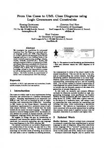
Figure 1. The Methodology for the design of Web Services. “correct” Web Services [4] by using UML diagrams [5] as design technique and model checking as verification technique. By “correct” Web Services we mean that they fulfill not only their funcitonal requirements, but also the timing restrictions defined on them. Figure 1 shows this generation process. In this figure the UML diagrams are translated into WS-CDL and WS-BPEL specifications that are also translated into Timed Automata in order to perform model checking on them. In this paper we focus our attention in the right-hand side of Fig. 1, i.e., the translation from UML into WSBPEL. Other parts of this Figure that we have already covered in some previous works [6, 7, 8] are those related with the translations of WS-CDL and WS-BPEL into timed automata. In [9] we design the Web Services systems by using an UML profile, RT-UML, in order to model the timed restrictions of these systems, and then we obtain the corresponding WS-CDL code.
Related Work We can find some related works in the literature, Mantell [10] proposes a methodology for translating UML activity diagrams into bpel4ws 1.0 Specification, and Skogan et al [11] propose another approach based on bpel4ws 1.1. In this paper we present a different vision, focusing our attention on the timed aspects of the systems, thus, we are mainly concerned with Web Services with time constraints, and then, we use Sequence Diagrams with time information modelled by means of frames.
Then, we note that Sequence Diagrams allow us to model Real Time Systems, since they offer us a key element for dealing with time. These are the frames, which extend the traditional sequence diagrams by adding some new capabilities, like the possibility to include new control sentences. A frame is defined as a unit of behavior and contains, among others, the set of objects that are in relation, and the sequence of messages between these objects. A frame is depicted by a solid-outline rectangle with a pentagon in the upper left corner of the rectangle, labelled with a name inside of it, which makes it easier to refer to it, e.g. as a subdiagram. In that sense, we can deal with the diagram composition problem. For example, it is possible to have a frame with the label ”loop” within the rectangle and a constraint indicating what is being looped through. This labeling frames capability allows us to introduce constraints over timed expressions. By using frames it is possible to structure the sequence diagram with control structures. The main contribution of this paper is to facilitate the design of Real-Time Web Services, starting from a graphical description of a Web Service business process; for that purpose UML [12] diagrams are very useful, since they allow us to see the system behavior in a clear way. More specifically, we use the sequence diagrams for that description, since these diagrams can capture the main elements of a Business Process, and then, in this paper we see how we can translate these diagrams into WS-BPEL documents. For that purpose we have developed a tool, called UML for Web Compositions, U4WC, which allows us to obtain WSBPEL documents from UML Sequence diagrams. As illustration of this methodology, we use a particular case study, an Aero Electric Management System, whose description contains some time constraints.
Overview The paper is structured as follows. In Section 2 we describe the main features of WS-BPEL. In Section 3 we present a brief description of the UML Sequence diagrams. The translation of UML Sequence diagrams into WS-BPEL documents is presented in Section 4. In Section 5 we apply this methodology to the case study. Finally, the conclusions and the future work are presented in Section 6.
2
WS-BPEL Description
The WS-BPEL specification, also known as Orchestration specification, is aimed at being able to precisely describe the behavior of any type of party an the collaboration among them, regardless of the supporting platform or programming model used by the implementation of the hosting environment. Using the WS-BPEL specification, a behavior containing a “specific” definition of the detailed or-
Second International Conference on Internet and Web Applications and Services (ICIW'07) 0-7695-2844-9/07 $20.00 © 2007
Figure 2. The relationship between the Choreography and Orchestration layers dering conditions and constraints under which behavior is performed, is produced that describes the specific internal behavior with the exchanged messages with all the parties involved. In real-world scenarios, corporate entities are often unwilling to delegate control of their business processes to their integration partners. Orchestration offers a means by which the rules of participation within a collaboration can be clearly defined. Each entity may then implement its processes as determined by the behavior described in the Orchestration document. Figure 2 demonstrates a possible usage of the Business Process Execution Language in collaboration with the main Web Services layers. Let us introduce the reader about WS-BPEL. It is an interface description language that describes the observable behaviour of a service by defining business processes consisting of stateful long-running interactions in which each interaction has a beginning, a defined behaviour and an end, all of this being modelled by a flow, which consists of a sequence of activities. The behaviour context of each activity is defined by a scope, which provides fault handlers, event handlers, compensation handlers, a set of data variables and correlation sets. Let us now see a brief description of these components: • Events, which describe the flow execution in an event driven way. • Variables, which are defined by using WSDL schemes, for internal or external purposes, and are used in the message flow. • Correlations, which identify processes interacting by means of messages. • Fault handling, defining the behaviour after an exception has been thrown. • Event handling, defining the behaviour after an event occurs.
• Activities, which represent the basic unit of behaviour of a Web Service. In essence, WS-BPEL describes the behaviour of a Web Service in terms of choreographed activities.
3
UML Diagrams for WS-BPEL Descriptions
UML 2.x considers thirteen different diagrams for software development. They can be divided into three groups: • Behavior diagrams. A type of diagram that depicts behavioral features of a system or business process. This includes activity, state machine, and use case diagrams as well as the four interaction diagrams. • Interaction diagrams. A subset of behavior diagrams which emphasize object interactions. This includes communication, interaction overview, sequence, and timing diagrams. • Structure diagrams. A type of diagram that depicts the elements of a specification that are irrespective of time. This includes class, composite structure, component, deployment, object, and package diagrams. Our interest in this paper is focused on one particular class of interaction diagrams, because with them we are able to capture the main features of the Choreography Layer. More specifically, we are interested in the sequence diagrams, because they represent the message flow of the different participants in the system. Sequence diagrams model the logic flow of the system in a visual manner, enabling the designer both to document and validate the logic. Sequence diagrams are used to capture the dynamic behavior of the system, together with other diagrams, like activity diagrams, communication diagrams, timing diagrams, and interaction overview diagrams. Figure 4 shows an example of a sequence diagram. This example shows an Aeroelectric Management System, which consists of three parts: wind generator management system or wind turbine management, productivity management system, and demand management system. This diagram shows an increasing demand event, which is detected by the Demand Management System. In order to represent this event, we have used a frame, labeled with ”opt” that performs the corresponding sequence of messages when the demand increasing is greater than a certain threshold. The wind turbine management system sends a report of production to the productivity management system every hour, which is modeled by using a frame, labeled with ”opt”, which performs the corresponding sequence of messages every hour, according to the frame condition.
Second International Conference on Internet and Web Applications and Services (ICIW'07) 0-7695-2844-9/07 $20.00 © 2007
Figure 3. Obtaining the WS-BPEL document with U4WC Tool. In that Figure we use a frame labeled with ”par”, to capture the parallel execution of two actions, we also use a frame labeled with ”loop” to repeat the same behaviour for this subsystem.
4
Translation from UML Sequence Diagrams into WS-BPEL
In this section we show the translation rules of the UML sequence diagrams into WS-BPEL XML format. Notice that we do not need to consider all the UML Sequence diagram elements, but only a subset of them, in order to obtain the corresponding WS-BPEL representations. This translation has been developed with XSLT [13], XML Stylesheets Language for Transformation, which is a language for transforming XML into other XML documents. In the market we can find some tools that allow us to model the UML diagrams and to obtain the corresponding XMI document, as IBM Rational Rose tool [14]. The XMI document generated by one of these tools can be easily translated to the XML WS-BPEL documents by using XSLT. For that purpose, we have developed a tool, U4WC, which performs this translation. Fig. 3 shows the main window of a primer version of this tool, where a UML sequence diagram is translated into WS-BPEL document, by means of XSLT, following the translation rules explained in this section. Tables 1 and 2 define the correspondence between the UML Sequence Diagram elements and WS-BPEL. Let us see a description of this translation: • Messages : The messages in UML Sequence diagrams correspond to the following entities of WS-BPEL: – PartnerLinkTypes: The partnerLinkTypes represent the interaction between a service and each of the parties with which it interacts. The main utility of PartnerLinkType is to characterize the relationship between two services, this is possible by defining the roles played by each of the services
UML Diagrams WS-BPEL Components Components Object
Syntax for the WS-BPEL Components
Process composed * ? ++ ? activity
Messages
Labels and Constrains
PartnerLinkTypes & Message (receive or request or reply) Time 1. Definition Variables
2.
Make Expressions
of type=”qname”? element=”qname”?/>+ from-spec? Use of Xpath 1.0 as the expression language.
3. Assignment the variables and standard-elements expressions. ( from-spec to-spec | ...assign-element-of-other-namespace... ) +
Table 1. Translation of UML Diagrams into WS-BPEL UML Diagrams WS-BPEL Components Components Frames. “opt” label It depends of the frame label.
“alt” label
“loop” label
Syntax for the WS-BPEL Components
standard-elements ... bool-expr ... Activity standard-elements ... bool-expr ... * ... bool-expr ... activity ? Activity standard-elements ... bool-expr ... activity
“par” label
standard-elements ? + activity+
Table 2. Translation of UML Diagrams into WS-BPEL participating in the conversation and specifying the portType provided by each service to receive messages. Each role specifies exactly one WSDL portType. • Objects : The objects in UML Sequence diagrams can be represented by the following entities in WS-BPEL: – Processes: In WS-BPEL we can find two types of processes, the execution process, and the abstract processes. Execution processes model the behav-
Second International Conference on Internet and Web Applications and Services (ICIW'07) 0-7695-2844-9/07 $20.00 © 2007
ior of each particular participant in the interaction, while abstract processes are meant to couple Web Service interface definitions with behavioral specifications that can be used both to constrain the implementation of business roles and to define in precise terms the behavior that each party in a business protocol can expect from the others. Then, the translation of the UML objects is made only by using the execution processes, since they allow us to model the behavior of each particular participant in an interaction. From the UML description we obtain the needed elements to complete the WS-BPEL process definition; more precisely: 1. Variables section: here the variables identified in the UML document must be declared. 2. PartnerLinks section: in this section the different parties that interact with this particular business process are declared. This information can be easily extracted from the UML document. Notice that each partnerlink must have a partnerlinktype (that models the interaction between the parties) and a role name, which is the other participant in the interaction. 3. FaultHandlers section: where the activities that must be performed in response to faults resulting from the invocation of the assessment and approval services. The information contained in this section is extracted from UML frames, and more specifically, those with the ”opt” and ”alt” labels. 4. EventHandlers section: here the activities that must be performed in response to events or alarms are described, and this information is taken from the UML frames, more specifically, from those having the ”criticalRegion” label. • Expressions : UML expressions are immediately translated into WSBPEL expressions, but the needed variables must be first declared in WS-BPEL. Notice that we should use XPath 1.0 to introduce the expressions in WS-BPEL. These expressions allow to express timed constraints in the UML Diagrams. Concening with assignments, we can use the assign activities of WS-BPEL to copy data from one variable to another, to construct and insert new data using expressions. • Frames. We consider the following kinds of frames:
– UML Frames labeled with ”par” are translated as flow Structured Activities, indicating the activities that are made in parallel. – UML Frames labeled with ”loop” can be translated as while or RepeatUntil Structured Activities in WS-BPEL, indicating iterative computations. – UML Frames labeled with ”opt” are translated as if Structured Activities. In the same way, the UML frames labeled with ”alt” are translated by using if-else Structured Activities.
5
Case Study: Aero Electric Management System
The case study that we use to illustrate how the translation works is an Aero Electric Management System. This system consists of three parts: wind generator management system or wind turbine management, productivity management system, and demand management system. The wind turbine management system sends a report of production to the productivity management system every hour and it controls wind turbines by turning on or turning off them according to the indication of the productivity management system. The productivity management system receives reports about the production from the turbine management system, analyzes these reports and decides how many turbines should work. The demand management system controls the wind power demand of a specific area, and then it generates a report for the productivity management system. Let us consider the situation when the demand of wind power increases over a certain threshold, and how we can model this situation by using a UML Sequence diagram. The starting point is that the demand of electric power increases a lot. The demand management system detects that it is necessary to increase the production of electric power. Then, it calculates how much power is necessary and sends a message to the productivity management system to increase the production. The productivity system decides how many turbines must be activated to increase the production, and it sends a message with this number to the turbine system in order to turn on these turbines. When the turbine system receives the message, if there are enough available turbines it turns on the required number of them, but if there are not enough turbines, it can only turn on all the available turbines, and sends a message to the productivity management system indicating the number of turbines that it has turned on. Figure 4 shows the Sequence Diagram for the described process that models an increment of the wind power.
Second International Conference on Internet and Web Applications and Services (ICIW'07) 0-7695-2844-9/07 $20.00 © 2007
Figure 4. Sequence diagram for increasing the production. ... Frame labeled with “loop” $true ==1 Frame labeled with “par” First Frame labeled
threshold”> with “opt” Clock-X + 2 $clock-X $clock-X+2 Second frame labeled with “opt”. Timed Constraint: “clock-X % 60 ==0” ...
Figure 5. WS-BPEL Document for Wind Turbine Management System. The U4WC tool works according to the rules defined in Tables 1 and 2, from these UML specifications we obtain a WS-BPEL specification written in XML. In Fig. 5 we can see a piece of the WS-BPEL document generated from the UML sequence diagram shown in Fig. 4, corresponding to the turbine management system process. This Figure shows how we can capture some timed restrictions in the system, concretely, we use the “assign” WSBPEL structure in order to model the clock defined in the UML Sequence diagram represented in Fig. 4 and to in-
crease its value in two units. In this Figure, the “if” WSBPEL structure allows us to model the timed restriction associated with the “opt[clock-x % 60 == 0]” frame, which controls that the Wind Turbine System send a report each hour.
6
Conclusions and Future Work
In this paper we have defined the translation rules that allow us to obtain a WS-BPEL description of a Web Service with Real-Time constraints initially described by an UML Sequence diagram. Then, we have implemented a tool supporting these rules, called UML for Web Compositions, U4WC. The U4WC Tool performs the automatic generation of WS-BPEL documents with timed constraints, starting from UML sequence diagrams, and this translation has been implemented by using XSLT. The motivation for this work is that descriptions of Web Services by WS-BPEL documents, written in XML format, can be very difficult to understand for non-experts, so starting from UML may facilitate the design and implementation of Web Services. Thus, we have established the equivalence between the main elements of the UML sequence diagrams with the elements of the WS-BPEL specifications, and we have illustrated this translation with an example. Our future work addresses the issue of enriching the capabilities of U4WC, in order to integrate the different steps indicated in Fig. 1 for the generation and verification of “correct” Web Services. Thus, our final goal is to describe a Web Service with time restrictions by using UML, and then, to obtain automatically the corresponding XML files for WS-BPEL, WS-CDL and Timed Automata. Then, we could execute the system by using the WS-BPEL representation, or we could analyze some properties of the system by using UPPAAL.
References [1] Assaf Arkin et al. Web services business process execution language version 2.0, December 2004. http://www.oasisopen.org/committees/download.php/10347/wsbpelspecification-draft-120204.htm.
2004. http://www.w3.org/TR/2004/WD-ws-cdl10-20041217/. [4] Gregorio D´ıaz, Mar´ıa-Emilia Cambronero, M. Llanos Tobarra, Valentin Valero, and Fernando Cuartero. Analysis and verification of time requirements applied to the web services composition. In Web Services and Formal Methods, volume 4148 of Lecture Notes in Computer Science, pages 178–192. Springer, 2006. [5] OMG. UML 2.0 Superstructure proposal v.2.0., January 2003. [6] G. Diaz, M. E. Cambronero, J. J. Pardo, V. Valero, and F. Cuartero. Automatic generation of Corect Web Services Choreographies and Orchestrations with Model Checking Techniques. In Proceedings of International Conference on Internet and Web Applications and Services ICIW’06. [7] G. Diaz, J. J. Pardo, M. E. Cambronero, V. Valero, and F. Cuartero. Verification of Web Services with Timed Automata. In ENTCS, vol: 157, issue: 2. [8] G. Diaz, J. J. Pardo, M. E. Cambronero, V. Valero, and F. Cuartero. Automatic Translation of WS-CDL Choreographies to Timed Automata. In Proceedings of WS-FM, 2005. LNCS, Springer–Verlag. [9] M. E. Cambronero, G. Diaz, J. J. Pardo, V. Valero, and Fernando L. Pelayo. RT-UML for modeling Real-Time Web Services. In Proc. of IEEE Services Computing Workshops. Modeling, Design, and Analysis for Service-Oriented Architecture Workshop, mda4soa, 2006, pages 131–139. IEEE Computer Society Press, 2006. [10] Keith Mantell. From UML to BPEL, September 2003. http://www106.ibm.com/developerworks/webservices/library/wsuml2bpel. [11] David Skogan, Roy Grønmo, and Ida Solheim. Web service composition in uml. In EDOC, pages 47–57, 2004. [12] Scott W. Ambler. The Object Primer: Agile ModelDriven Development with UML 2.0. Cambridge University Press, New York, NY, USA, 2004.
[2] Nickolas Kavantzas et al. Web Service Choreography Description Language (WSCDL) 1.0. http://www.w3.org/TR/ws-cdl-10/.
[13] James Clark. XSL Transformations (XSLT) Version 1.0. Technical Report REC-xml-19980210, W3C, 1998. http://www.w3.org/TR/xslt.
[3] Nickolas Kavantzas, David Burdett, Gregory Ritzinger, Tony Fletcher, and Yves Lafon. Web services choreography description language version 1.0. World Wide Web Consortium,
[14] Terry Quatrani. Visual modeling with Rational Rose and UML. Addison-Wesley Longman Publishing Co., Inc., Boston, MA, USA, 1998.
Second International Conference on Internet and Web Applications and Services (ICIW'07) 0-7695-2844-9/07 $20.00 © 2007