to the optimal rate in one step, while eliminating the reliance on empirical measurements. Moreover, Ac-. cuRate's approach scales to arbitrarily high bit rates,.
AccuRate: Constellation Based Rate Estimation in Wireless Networks Souvik Sen
Naveen Santhapuri
Duke University
Duke University
Romit Roy Choudhury
Srihari Nelakuditi
Duke University
University of South Carolina
Abstract This paper proposes to exploit physical layer information towards improved rate selection in wireless networks. While existing schemes pick good transmission rates, this paper takes a step further towards computing the optimal bit rate. The main idea is to capture the channel behavior through symbol level dispersions, and “replay” these dispersions on different rate encodings of the same packet. The “replay” action can be emulated at the receiver without requiring the transmitter to send the packet at every other rate. The maximum successful rate is likely to be the optimal rate of the received packet, and assuming that the channel remains coherent, the same rate can be prescribed for the next transmission. We design, implement, and evaluate this idea over a small testbed of USRP hardware and GNURadio software. Our proposal, called AccuRate, predicts a packet’s optimal rate 95% of times when the packet is received correctly. When the packet is received in error, AccuRate computes its optimal rate with 93% accuracy. In terms of throughput, we show that AccuRate improves over the state-of-the-art scheme SoftRate by around 10%, and is reasonably close to the optimal.
1
Introduction
Rate estimation is an important problem because it directly translates to throughput. The difficulty in rate estimation stems from channel fluctuations – the optimal rate quickly becomes stale, requiring a fresh round of estimation [1–3]. WiFi rate control is performed at the link layer, and hence, must operate on the granularity of packets. Approaches such as ARF [4], RRAA [5], and SampleRate [2] continuously track the success/failure of packets, and employ statistical prediction methods to select the appropriate rate. To improve responsiveness to channel fluctuations, alternate schemes have explored the use of SNR for rate selection. RBAR [6] and OAR [7] were the first-generation schemes that utilized RTS/CTS to exchange SNR values. However, with
recent consensus to turn off RTS/CTS, new schemes are recording historical SNRs and deriving a rate-versusSNR relationship from it [8, 9]. While this improves performance, continuously refreshing the SNR for every rate is often difficult [9]. Moreover, the rate-vs-SNR relationship changes with different propagation environments, especially when the channel changes quickly over time [1]. Therefore, although practical SNR-based schemes are reasonably good at slower time-scales, they lack the agility to achieve per packet rate adaptaion in dynamic wireless environments. This paper proposes to exploit physical layer information (such as symbol level dispersion on a constellation space) to improve the accuracy of rate selection. We show that such PHY layer information can be derived from a received packet, and then used to compute the optimal rate at which that packet should have been transmitted. Although the optimal rate is computed in retrospect, it can be valuable for guiding the transmission rate of subsequent packets. Moreover, symbol level information can discriminate between losses due to fading and interference, further assisting in link layer retransmission strategies. Our ideas are consolidated into a constellation based rate estimation scheme, called AccuRate. We show that the improvements from AccuRate are consistent over diverse wireless environments. AccuRate’s main idea is intuitive. Given that the PHY layer encodes a sequence of bits into a symbol on the constellation space, AccuRate looks at the dispersion between the transmitted and received symbol positions. Small dispersions indicate that the communication link is strong, and perhaps capable of supporting higher rates than the one used. By comparing these dispersions to the permissible dispersions at different bit rates, AccuRate can precisely derive the maximum rate the packet could have been transmitted at. Even when the packet fails, AccuRate extracts known parts of the packet (preamble and postamble [10]), and estimates the appropriate rate from them. Of course, this is a retrospective analysis of
a just-concluded transmission. However, as argued earlier, knowing the optimal rate of a received packet is a valuable primitive for rate control algorithms. The AccuRate receiver prescribes this rate to the transmitter, which in turn uses it for the next transmission. So long as the channel remains coherent between two consecutive packets, AccuRate achieves a near-optimal rate selection accuracy.
2
This paper is not the first to use PHY layer information towards rate estimation. Recently, authors in [1] proposed SoftRate, a scheme that uses PHY layer confidence values to estimate a packet’s bit error rate (BER). By comparing the BER against an empirically generated lookup table, the transmitter picks a “good” bit rate for subsequent transmissions. While SoftRate makes a valuable contribution, we show that there is room for improvement. Specifically, we show that by directly operating on symbol constellations, AccuRate can “jump” to the optimal rate in one step, while eliminating the reliance on empirical measurements. Moreover, AccuRate’s approach scales to arbitrarily high bit rates, and does not require large gaps between the consecutive rates. Experiments performed in a wireless channel simulator [11] (where the channel conditions can be repeated for fair comparison) demonstrates that AccuRate reliably selects the optimal rate. Similar experiments on a prototype USRP testbed show consistent throughput gains under various wireless environments. Together, these results confirm that AccuRate advances the state of the art through PHY-aware rate estimation. AccuRate’s key contributions can be summarized as follows.
History based: SampleRate [2] by Bicket adapts transmission rate by periodically probing the channel with packets at various bit rates. The idea is to adapt to changing channel conditions and minimize the overall transmission time for the packets. In RRAA [5] the authors propose faster rate estimation than SampleRate by using loss information from short frame windows. Frame error history based schemes like SampleRate and RRAA do not distinguish between fading and collision which is significant for rate estimation. This class of schemes are also slow to converge, and may not converge at all, if channel conditions change frequently. AccuRate distinguishes between fading and collisions and has a onepacket convergence-time to estimate the best rate supported by the channel.
• Identify the opportunity of rate estimation using symbol dispersion at the PHY layer. We verify our ideas through measurements on the USRP/GNURadio platform. The findings offer new insights for further research at the link layer. • Develop a constellation based rate estimation scheme (AccuRate) that “jumps” to the appropriate rate. The wireless channel manifests itself through symbol level dispersions. By “replaying” the dispersions on packets at different rates, AccuRate is able to identify the best bit rate of a packet. This bit rate is prescribed for future transmissions. • Implement and evaluate AccuRate on a USRP testbed, and on a emulation platform composed of USRPs and a wireless channel simulator. Results from 25 hours of testbed experimentation shows consistent improvement in performance over existing schemes. Emulation results (enabling experiments under controllable and repeatable channel conditions) exhibit similar trends.
Related Work
Perfect bit rate selection in wireless networks is an eluding problem that has been researched extensively in the past [1, 2, 4–9, 12–18]. Existing schemes have been broadly classified as frame-level or SNR-based, and has been well surveyed in [1]. Here, we touch upon only the recent works relevant to AccuRate.
SNR-based: Two recent SNR-based schemes take a cross layer approach to perform rate estimation. In [9], Camp and Knightly show that SNR-BER relationships change with the operating environment and therefore need training to operate in a particular environment. They also compare existing SNR-based schemes with SNR-trained schemes to show that trained SNR schemes perform considerably better. In [17], the authors demonstrate the utility of adaptive modulation per frequency band. The variation of channel characteristics across frequency sub-bands accentuates the effect in ultra wide band regimes which will benefit the most from such schemes. To perform well these schemes need in-situ training for each environment. AccuRate does not need any training or information about the environment. Collision vs. Fading: Collision detection has been an area of active research and lately several schemes have been proposed [19–23]. The scheme in COLLIE [20] allows a transmitter to distinguish between a fading and a collision loss by having the receiver send back the erroneously received packet. This allows the sender to identify the corrupt bits (via comparison with the original packet), and then analyze the cause of failure by analyzing the corruption patterns. Of course, the scheme depends on proper packet reception from the receiver in a timely manner. In [22], the authors propose a way to distinguish between collisions and fading, and adapt rate based only on the errors due to fading. This scheme is still history based and suffers from the same pathologies associated with other similar schemes. The use of OFDM symbol dispersions was shown in [23] as a
technique to distinguish between collision and fading. Our work goes beyond making this distinction by using known dispersions to select the correct rate. SoftRate: The closest proposal to AccuRate is SoftRate [1], which was the first to exploit PHY layer information for rate estimation. We therefore focus on explaining the differences between SoftRate and AccuRate. SoftRate achieves high quality rate estimation using a cross layer approach, but we believe there is room for improvement. Specifically, SoftRate estimates the rate supported by the channel based on the BER of the received packet. The BER is an average of SoftPHY confidence values, computed from the dispersion of the received symbols from their nearest constellation symbols. SoftRate employs a heuristic to predict the BER at other bit-rates using the BER estimate at a given bit rate1 . While this heuristic can effectively indicate when the rate must decrease to the next-lower bit rate (or increase to the next-higher bit rate), the ability to jump directly to the best rate is limited. In contrast, AccuRate’s ability to replay the channel distortion on all possible rates facilitates selection of the best rate in one step. The replaying mechanism is expected to scale to bit rates at potentially finer granularity. However, unlike SoftRate, the hardware cost and implementation complexity may be excessive. To balance performance and complexity, one may envision a combination of AccuRate and SoftRate – a topic of future research.
3
Background and Observations
We present some background material on PHY layer encoding/decoding of bits with different modulation schemes. Building on this understanding, we observe that the extent of signal distortion due to channel fading is independent of the modulation scheme. We validate this through USRP/GNURadio measurements, and use it as a pivot for subsequently proposed ideas.
3.1
The PHY layer encodes a sequence of bits into a PHY symbol which is represented by a position on a 2D complex plane called the constellation diagram. Figure 1(a) shows an ideal constellation diagram from 16-ary quadrature amplitude modulation (16QAM). If the transmitter wishes to send a bit sequence “0000”, it sets the In-Phase (x-axis) and Quadrature (y-axis) to a value of . The receiver recovers the I and Q values after demodulation, and plots each symbol on the IQ plane. Since the channel distorts the transmitted signals, the received symbol positions get dispersed from their ideal positions. Let ~ri be the received symbol position and ~si be its ideal symbol position. We define its dispersi sion as d~i = ~ri~s−~ . This is essentially the Error Vector i Magnitude (EVM) [24, 25], but for ease of understanding, we refer to it as dispersion. Figure 1(b) shows an example of the dispersed symbols at the receiver. To decode the symbols, for each received symbol position, ~ri , the receiver guesses the corresponding ideal symbol position, ~si . A simple method is to pick the symbol that is closest to the received symbol position ~ri . In other words, there is a tile associated with each symbol in the constellation. When a symbol ~si is received correctly, its received position falls within the symbol’s tile, i.e., ~ri ∈ tile(~si ). When all the symbols in a packet are received correctly, the corresponding bits will pass the CRC check and the packet is handed to the upper layer. With channel fading or interference from nearby transmissions, the received symbol position ~ri may be quite far away from the transmitted symbol position ~si . The received position ~ri may even fall outside the tile of ~si , i.e., ~ri ∈ / tile(~si ). Then, ~ri will be closer to another symbol position than ~si , misguiding the receiver to believe that some other symbol was transmitted instead of ~si . This error will be caught later when the CRC check on the packet fails. Of course, channel coding techniques, such as forward error correction (FEC), may be effective in correcting some errors in demodulation. If the number of errors are large, even channel coding may not be adequate to recover the packet.
3.2
Figure 1: Symbol constellation for 16QAM: (a) Each symbol corresponds to a 4-bit sequence. (b) Symbols received after suffering channel-induced dispersions. 1 The heuristic exploits the empirical observation that, under a given SNR, adjacent bit rates experience a factor of 10 difference in BER.
PHY Layer Symbol Constellations
Relation between Transmission Rate and Symbol Constellation Density
For ease of explanation, let us ignore channel coding for now and assume that each symbol encodes the actual bits from the packet. Observe that a higher transmission rate is realized by encoding a longer bit-sequence on a symbol. Thus, if one increases the length of the sequence from 2 to 4 bits per-symbol, the constellation diagram must also accommodate a greater number of symbols (from 4QAM to 16QAM). In other words, the den-
I
QAM16
QAM64
Q
Q
QPSK
Q
Q
BPSK
I
I
I
Figure 2: Symbol density increases with increasing data rates (BPSK, QPSK (or 4QAM), 16QAM, 64QAM).
Testbed 64QAM
16QAM
Almost-identical curves provide evidence that the dispersions are independent of the symbol constellation, and therefore the transmission rate. More detailed experimental evidence is presented in [25]. Testbed 1
Fraction of symbols
sity of symbols in the constellation diagram increases at higher rates as shown in Fig. 2. Since increased density implies shorter distance between neighboring symbols, the received packet is more susceptible to errors at higher rates when the channel is weak. Figure 3 confirms this by showing that the maximum tolerable BPSK error (|si − ri |) can be twice that of QPSK (or 4QAM), and four times that of 16QAM. This well-known observation will underlie the design of AccuRate.
0.8 0.6 0.4
BPSK QPSK 16QAM 64QAM
0.2 0 0.2 0.4 0.6 0.8
QPSK
1
1.2 1.4 1.6 1.8
2
2.2
Symbol dispersion magnitude BPSK 0 0.2 0.4 0.6 0.8 1 1.2 1.4 1.6 1.8 Scalar Distance between Ideal and Received Symbol
Figure 3: Lower rates can tolerate higher magnitude of symbol dispersion
3.3
Relation between Dispersion due to Channel Fading and Bit Rate
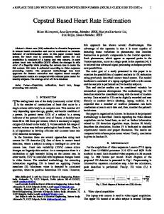
We now demonstrate that symbol dispersion is not influenced by the modulation scheme (or transmission rate), and is only a function of the channel. We transmit data from a static USRP sender to a static USRP receiver using 2, 4, 16, and 64 QAM. We maintain as much coherence in the channel as possible (by keeping the physical environment static), and transmit small packets repeatedly using different modulation schemes in a round robin manner. For every received symbol, we calculate its dispersion from the correct constellation symbol2 . Figure 4 plots the CDF of symbol dispersion magnitude for each modulation scheme for packets transmitted in one round. 2 The correct constellation symbol is known because the transmitted packet is known in our experiments. Thus, even when a packet fails, we can still compute the correct dispersions.
Figure 4: CDF of symbol dispersion magnitude for packets transmitted with different modulation schemes. Not all packets were received correctly, but their dispersions could be computed offline using the (known) transmitted packet. These observations enable us to model the channel behavior based on the dispersion of known symbols at the receiver. The receiver can then conduct a what-if analysis by “replaying” the channel on a packet encoded at different rates. For instance, Fig. 5(a) shows the dispersion of symbols when a packet was transmitted using 4QAM. Given that the dispersion is independent of the modulation, the receiver can check whether a higher modulation such as 16QAM with denser constellation could have tolerated the same level of dispersion. In other words, 16QAM is feasible if all the received symbols in each 4QAM quadrant can be accommodated in a smaller 16QAM tile (drawn with dashed grids) as in Fig. 5(b). The original 16QAM grid, as shown in Fig. 7 has been shifted and superimposed on Fig. 5(b) for the purpose of demonstration. In this example, 16QAM is not feasible since some received symbols spill out of their correct tile. More generally, this shows that the outcome of a 16QAM transmission may be predicted without actually transmitting the packet over the air. Repeating this over all possible bit rates will reveal the best possible rate for
1
0. 7
0. 7
1
Figure 6: Flowchart of determining the optimal rate in retrospect.
1
0. 7
0. 7
1
Figure 5: Receiver checks if QPSK (4QAM) packet could have sustained higher bit rate (16QAM). this just-received packet3 . Such a retrospective analysis can guide us in subsequent rate control decisions. The details on how this hindsight is leveraged is described in the following sections.
4
Determining The Optimal Transmission Rate in Retrospect
We now explain how a receiver can determine from a received packet, what could have been the optimal rate, for transmitting that packet. A high level schematic of the procedure is depicted in Fig. 6. We present the rate computation method for three cases: (1) when the packet is received successfully, (2) when the packet fails due to fading, and (3) when the packet fails due to interference. We support our basic claims with measurements from the USRP testbed.
4.1
In Case of Successful Packet Reception
Let us first consider the case where a packet is successfully received. Since all the bits are decoded correctly, the receiver is aware of all the transmitted symbols. Hence, it can compute the dispersion d~i , between 3 The what-if analysis with “replay” operation is applicable even with channel coding as discussed later in Section 4.1.1
each transmitted symbol position ~si and received symbol position ~ri . Assuming N symbols in the packet, the ~ a sequence of channel can then be characterized by D, ~ ~ ~ ~ dispersions, i.e., D = {d1 , d1 , · · · dN }. Now, suppose the packet was transmitted at a bit rate of R. Given that it was received successfully, it is clear that the symbolconstellation density corresponding to R can tolerate the ~ Now the question is what is the highest dispersion D. ∗ rate, R (≥ R), at which the transmission would have been successful over a channel with dispersion sequence ~ D. ~ is independent of the Note that, as argued before, D modulation used by the transmitter, i.e., the i’th symbol gets dispersed by d~i regardless of whether that symbol is from the constellation of BPSK, QPSK, 16QAM, or 64QAM. Consequently, the receiver can analyze the outcome of different modulations without requiring the transmitter to explicitly send the packet once per each modulation. The procedure to check whether a transmission at a higher modulation would be successful is as follows. For each symbol i, we apply the dispersion vector d~i on its ideal position s~i in the constellation space and check if the resulting symbol position would still be correctly decoded. If that position happens to be closer to some other constellation point (i.e., in some other tile), this constellation is too dense for this dispersion. In this manner, the most-dense constellation is chosen in which, for each symbol i, d~i is completely contained in the same tile. Figure 7 illustrates this checking operation – a symbol received through BPSK modulation is being tested against a 4QAM and 16QAM constellation. In this example, the channel-induced dispersion can be tolerated by a 4QAM symbol, whereas a 16QAM symbol will not be decoded correctly as it’s received position falls in the wrong tile. Ignoring error coding, this implies that 16QAM is an inappropriate rate for transmitting this
packet. However, 4QAM may prove to be suitable, provided all the symbols in the packet passes this test successfully.
si di si di
ri
ri si
so long as the dispersions are precisely known, the replaying operation is no different from an actual transmitreceive operation. As will be clear from Section 5.2, even the same hardware chain may be reused for both the actual reception and the replayed operation. This implies that, as long as a packet is received correctly, AccuRate can retrospectively compute its optimal bit rate, and use it for the subsequent transmission.
di ri
4.2 Figure 7: Computing the appropriate rate at which this packet reception would have been successful. In this case BPSK and QPSK will be successful where as 16QAM will not. 4.1.1
Error Correction with Channel Coding
We now introduce the role of channel coding in rate computation. Briefly, channel coding helps in error correction by including redundant bits in the packet. Some symbols may fall in the incorrect tile on the constellation, but channel coding may still be able to correct them. This implies that coding can allow for a denser constellation, at the expense of a larger packet size. The net result is a new intermediate rate between the sparse and the dense constellation. To clarify with an example from 802.11g, 4QAM results in 24Mbps. However, data rate 18Mbps can be achieved if the 4QAM modulation is combined with a 3/4 coding scheme. Thus, channel coding allows for additional data rates, offering finer-grained choices to the rate selection algorithm. With coding, our goal then is to precisely identify the best tuple at which this packet would have been successful. For this, the receiver considers every higher modulation scheme, and computes the fraction of symbols that would have been in error. Note that the higher the modulation, the more the number of errors, and the larger the number of redundant bits. Suppose a modulation M1 needs 3/4 coding to correct errors and a higher modulation M2 requires more redundant 1/2 coding. Let R1 and R2 be the rates corresponding to M1 and M2 respectively. Then, the effective rates (after accounting for the overhead due to coding) would be 34 R1 and 12 R2 . The higher effective rate is then chosen as the best rate in retrospect, i.e., R∗ = max( 43 R1 , 12 R2 ). Besides offering bit rates at finer granularity, channel coding also allows for precisely computing the symbol dispersions. If a packet is known to pass the CRC check, the exact dispersion can be computed for all the symbols in that packet. These dispersions can then be recorded and replayed on higher-rate packet encodings to estimate the best bit rate. Observe that a packet may be successful even if some replayed dispersion causes the symbol to fall in an incorrect tile – channel coding may absorb these errors, similar to over-the-air reception. In other words,
In Case of Packet Loss due to Fading
Let us now consider the case where a packet is not received correctly, and the receiver has to find the smallest rate reduction that would have resulted in a successful reception. This is more challenging because, unlike the above case, the receiver does not know the actual transmitted symbol ~si for every received symbol position ~ri . Since the packet failed the CRC check, some ~ri must have been outside the tile of the correct symbol ~si and inside the tile of some other symbol. The receiver does not know which of the symbols are incorrectly decoded and so it can not precisely compute for each symbol the dispersion d~i caused by the channel. Fortunately, each packet starts with a preamble, a globally known sequence of bits, that the receiver uses to detect and synchronize onto a newly arriving signal. The receiver can utilize the preamble to estimate dispersion [26]. Suppose the preamble consists of k symbols pre pre pre and their computed dispersions are d~1 , d~2 , · · · , d~k . We subject this sequence of k dispersions to the whole packet, i.e., we compute the dispersion for i’th symbol pre in the packet as d~i = d~i%k . Given this set of d~i vectors, we try to estimate the optimal rate R∗ using the same approach as described earlier. The preamble’s symbol dispersions will only capture the channel behavior in the earlier parts of the packet. If the channel changes over time, the later changes will remain unquantified. Therefore, to better cope with channel variations, a postamble [10] may be inserted at the end of the packet. Suppose the postamble also consists of k sympost post post bols and their dispersions are d~1 , d~2 , · · · , d~k . Given the original packet size of N symbols, and a randomly generated packet of N or more symbols, we subject the ith symbol in the random packet to a dispersion pre d~i , computed as follows: If i < N2 , then d~i = d~i%k , else post d~i = d~i%k . The rationale is that the preamble is a better representative of the first half of the original packet duration, while the postamble is better for the rest of the duration. Also, when the random packet is encoded at a lower rate, the number of symbols increase. The postamble is likely to be a better estimate of the channel for these symbols as well. Once again, based on d~i vectors obtained thus, we try to estimate the optimal rate of the
packet, R∗ . The overhead of postamble would be justifiable if that leads to throughput improvements due to better rate estimation.
4.3
In Case of Packet Loss due to Interference and Fading
Rate selection must be approached somewhat differently when interference is the cause of packet failure. Under interference only, the transmitter should ideally backoff and transmit at the same rate. Under both interference and fading, the ideal approach is to backoff but transmit at a rate that accounts for the channel’s fading component. We approach this problem by looking at both the preamble and the postamble. The presence of a preamble and postamble in a packet offers multiple “glimpses” into how the channel varied during packet reception. Because both preamble and postamble are known, the receiver computes their respective dispersion vector sequences ~ pre and D ~ post . Using statistical methods, we comD pute the similarity of these sequences (detailed in Section ~ pre and D ~ post would 6). If there was no interference, D be similar and the loss is attributed to fading. Otherwise, depending on whether the interference overlapped ~ pre or D ~ post would with the preamble or postamble, D exhibit a higher dispersion than the other. If rate must be selected only in response to channel fading, then we ~ pre , D ~ post ). Of course, must select R∗ based on min(D when the interference overlaps with both the preamble ~ pre and D ~ post will be similar, and and the postamble, D our approach will incorrectly select a lower-than-optimal rate. Also, if the interfering packet is small enough to fit within the preamble and postamble of a transmission, AccuRate will fail to prescribe backoff although it will still estimate the rate induced by fading alone. One way to alleviate this problem is to insert known ”midambles” in different parts of the packet thereby allowing for multiple glimpses into the channel behavior. We discuss these possibilities in section 7.
4.4
Experimental Validation
The above approach, AccuRate, raises a few obvious questions about its feasibility and performance. How accurately can a receiver determine the optimal rate in retrospect? Is the preamble sufficient or the postamble also necessary for estimating the rate in case of packet loss due to fading? To answer these questions, we conducted experiments on a Rayleigh fading channel simulator [11] and a real testbed. The evaluation setting is described in detail in Section 6. Briefly, in the simulator we froze the channel parameters for a Rayleigh fading model in GNUˆ (by transmitting at Radio and computed the ideal rate R all rates). Next, we allowed the receiver to determine the optimal rate R∗ from the received packet under identical channel conditions. We repeated this experiment with
different channel parameters and transmit powers. Overˆ and R∗ for more than 2000 packall, we compared R ets. Fig. 8(a) shows the comparison by plotting the difˆ rate levels (e.g., successive ference between R∗ and R 802.11 bit rates such as 24 Mbps and 18 Mbps are separated by 1 rate level). These results indicate that when ˆ for every inthe packets are received correctly, R∗ = R stance. Even with preamble alone, AccuRate can determine the rate correctly in 80% of the cases, and the addition of postamble improves the accuracy to 95%. The postamble samples help AccuRate better estimate wireless channel coefficients using symbol dispersion. We observed similar results over a real wireless channel between a USRP/GNURadio transmitter and receiver pair – Fig. 8(b) shows these results. The above description and supporting results offer reason to believe that symbol dispersion information gathered from a received packet can be used to estimate the packet’s optimal rate. Considering that the channel coherence time is expected to be in the order of multiple packets, the receiver can prescribe the same rate for the subsequent transmission. One could argue that the optimal rate for the previous packet may not be optimal for the next packet or may even cause packet loss. But note that every rate adaptation scheme has to speculate the future channel conditions based on the past measurements. Any scheme that is not overly conservative and attempts to extract the best throughput from the channel runs the risk of packet loss. However, since our approach is based on fine grain information about the channel, the next packet has a reasonable chance of succeeding at the prescribed rate. In the following section, we gather our ideas into a single Constellation Based Rate estimation protocol, called AccuRate.
5 5.1
AccuRate Protocol and Implementation Protocol
The AccuRate module is located at the boundary of the PHY and MAC layer. For every outgoing frame, AccuRate concatenates it with a postamble. Upon reception of this packet, the AccuRate receiver performs the following checks and reacts accordingly. If the packet is correctly received, AccuRate estimates the best transmission rate, and piggybacks it in the acknowledgment (ACK). If the packet is incorrectly received (meaning that the preamble was decoded but the CRC check failed), AccuRate triggers an interference-detection operation. Learning that the failure was not due to interference, AccuRate estimates the appropriate rate using only the pre/postambles [1], and conveys this back through a negative acknowledgment (NACK). However, if interference was the cause of failure, AccuRate performs rate estimation using either the interference-free preamble or postamble, depending on which exhibits lower symbol
Simulation
Testbed
1
0.8 0.6 0.4 AccuRate correct-packets AccuRate using preamble AccuRate pre+postamble
0.2 0
Fraction of Packets
Fraction of Packets
1
0.8 0.6 0.4 AccuRate correct-packets AccuRate using preamble AccuRate pre+postamble
0.2 0
-1
0
1
(AccuRate Rate) minus (Optimal Rate)
-1
0
1
(AccuRate Rate) minus (Optimum Rate)
Figure 8: Accuracy of determining the optimal rate in retrospect: (a) simulation; (b) test bed. The x-axis is expressed in rate levels, where two successive 802.11 rates are assumed to have a rate level difference of one. The AccuRatecorrect-packets and AccuRate-pre+postamble curves overlap. These results correspond to channel conditions with fading but without interference (impact of interference on AccuRate is evaluated in Section 6). The optimal rate in the testbed scenario is determined by sending a train of small packets at all possible rates. (details in Section 6.1) . dispersion. AccuRate conveys this fading-induced rate in the NACK, but also instructs the transmitter to backoff according to regular 802.11. In the worst case, if the packet’s preamble itself is non-decodable, AccuRate cannot perform any rate prediction. The transmitter does not receive any ACK/NACK, and retransmits the packet as per the 802.11 specifications. In all other cases, the transmitter adopts AccuRate’s rate and backoff prescriptions, and prepares accordingly for the next transmission to the same receiver.
5.2
Implementation
AccuRate builds on the OFDM codebase for the USRP/GNU-Radio platform. We adopt the publicly available building blocks of SoftRate (like the BCJR decoder [27]) for building AccuRate. This facilitates a platform for fair comparison between the two. 802.11a/g specified modulation schemes and channel coding rates are used (Table 1) in an attempt to emulate 802.11 like scenarios. The transmitter encodes the data using a standard rate-1/2 convolutional encoder, and applies puncturing to achieve varying code rates. The bandwidth is fixed at 20 MHz for GNURadio simulations and at 2 MHz for testbed experiments. We have incorporated a Rayleigh fading channel simulator [11] into the GNURadio codebase. The OFDM implementation uses an FFT length of 1024, with 394 occupied tones, 8 pilot tones and a cyclic prefix of length 256. Figure 9 presents the block diagram for AccuRate’s implementation in GNURadio. SoftRate is also shown as a comparison point, especially because the two schemes use very similar modules. In SoftRate, an incoming packet is demodulated and passed through the BCJR
decoder. The output of the BCJR decoder comprises the data bits and their respective confidence values. These are passed through a BER computation module, resulting in the actual packet and its single BER. The SoftRate estimation algorithm runs in the “Select Rate” module, which picks the packet’s rate by comparing the BER against a BER-Rate relationship curve. The final ∗ output, RSof tRate , is SoftRate’s prescribed rate. We note that AccuRate uses a similar module chain with a few augmentations. When the over-the-air packet arrives, AccuRate measures the symbol level dispersions from the demodulator and stores it in the Build Dispersion Model module. This module uses the correctly received packet to calculate the accurate per-symbol dispersion4 . In addition, a random packet is generated and encoded at different rates (R1 , R2 , ...Rn ). Symbols from each rate-encoded packet are then subjected to the recorded dispersions, and the output is passed through the demodulator. Although Figure 9 shows the operations in parallel (incurring an additional hardware cost), we use a single chain in our GNURadio implementation and iterate over all possible rate encodings (imposing a higher processing latency). The output of the demodulator, denoted Demod, is fed into the BCJR decoder. The output bits are collected into a frame and checked for CRC (the confidence values are not used in AccuRate). If the CRC check passes at that rate, AccuRate deems the corresponding rate to be successful. AccuRate picks the maximum of all successful rates, and prescribes it for the subsequent transmission. 4 If the over-the-air packet failed, the dispersion sequence is suitably built from the preamble and postamble only.
SoftRate Channel
At Tx
BER-Rate
Demod Mod/Encode
Build Dispersion Model
BCJR Decoder
BER
Select Rate
R* SoftRate
AccuRate
Correct bits
Channel Replay Module Mod/Encode at rate r1
Build Random Packet
SoftPHY hints
Mod/Encode at rate r2
Mod/Encode at rate rn
yes
Demod at r1
BCJR
Demod at r2
BCJR
Demod at rn
BCJR
CRC ?
r1
m yes a x CRC ? r2
r a yes t e CRC ? rn
R* AccuRate
Figure 9: Block diagram of AccuRate
Table 1: 802.11 Modulation and coding used in AccuRate (20Mhz channel) Modulation Coding 802.11 rate (implemented?) BPSK 1/2 6 Mbps (yes) BPSK 3/4 9 Mbps (yes) QPSK 1/2 12 Mbps (yes) QPSK 3/4 18 Mbps (yes) 16QAM 1/2 24 Mbps (yes) 16QAM 3/4 36 Mbps (yes) 64QAM 2/3 48 Mbps (no) 64QAM 3/4 54 Mbps (yes)
6 6.1
Evaluation Methodology
We faced two challenges while evaluating AccuRate. (1) The wireless channel changes over time making it difficult to determine what could have been the optimal rate for a given transmission. (2) The high latency incurred in procuring RF samples from the USRP front-end makes it impractical to evaluate AccuRate in realtime. In view of these, we make two approximations in our experimentation methodology. First, we incorporate a Rayleigh fading simulator into the GNURadio codebase. The simulator [11] employs the same USRP/GNURadio transmitter and receiver, only connects them through a loopback configuration. Packets flow out of the
transmitter, and instead of advancing through the wireless channel, they are made to flow through simulated channel conditions. The output of the channel simulator is presented to the receiver which then executes regular demodulation/decoding. Since the simulated channel conditions can be forced to remain unchanged, we are able to compare the optimal bit rate for a given transmission against those prescribed by AccuRate and other schemes. Our second approximation is designed to test the performance of AccuRate over real wireless channels. To this end, we repeatedly transmitted trains of packets, each train comprising of 7 short packets (each 200 bytes) at increasing bit rates. Assuming that the channel is coherent for the duration of the packet train, we determine the optimal transmission rate R∗ by recording the highest bit rate successful in that train. Now, AccuRate picks a random packet in the first train, predicts the optimal rate ∗ for that packet RAccuRate . The operation is performed ∗ offline – the difference between R∗ and RAccuRate characterizes AccuRate’s rate selection accuracy. Moreover, ∗ the packet corresponding to RAccuRate in the next train is also selected, as if that’s the transmission that AccuRate would have executed. This packet’s transmission at ∗ RAccuRate is then used to predict the subsequent transmission rate, and so on. The throughput is computed based on the success/failure of the packets selected in each train. SoftRate’s performance is also compared in
Performance Results
We have designed experiments to answer the following key questions about the performance of AccuRate. (1) What is AccuRate’s rate estimation accuracy compared to the optimal rate and other existing schemes? (2) How does the accuracy vary under different channel conditions? (3) How well does AccuRate discriminate between fading and interference? How does interference affect rate selection? (4) What is the accuracy of rate estimation based on preamble and postamble dispersions? To understand AccuRate’s performance against existing schemes, we also evaluate SoftRate and SNR-based rate estimation. SNR-based rate uses the SNR feedback to pick the transmission bit rate. The SNR-rate relationship is derived a priori from a wide range of empirical measurements on USRP/GNURadios.
1
Fraction of Packets
6.2
Testbed
0.8 0.6 0.4 AccuRate Softrate SNR based
0.2 0 -1
0
1
2
(Estimated Rate) minus (Optimal Rate) Simulation 1
Fraction of Packets
these settings. Thus, while simulators provide faithful comparisons under approximate channel models, packettrain based evaluations attempt to achieve the converse. We believe that together, these experiments provide a fair comparison between AccuRate, SoftRate, and the Optimal rate selection algorithms.
0.8 0.6 0.4 AccuRate Softrate SNR based
0.2 0
Rate Selection Accuracy
-2
-1
0
1
2
3
(Estimated Rate) minus (Optimal Rate)
We evaluated the accuracy of rate estimation by AccuRate and other schemes in both slow fading (walking) and fast fading (driving) scenarios as described below. Slow Fading: We induced slow fading by moving the USRP transmitter on a wheeled chair, while it is transmitting to a fixed USRP receiver. We transmitted 500 packet trains where each train has one packet per rate. We repeat this experiment 10 different times and thus resulting in a total of 5000 packet transmissions per each bit rate. Figure 10(a) shows the results of these testbed experiments by plotting the CDF of the estimation accuracy. A negative value of the difference between estimated rate and optimal rate indicates underselection and a positive value indicates overselection. AccuRate selects the optimal rate nearly 95% of the time, which is around 10% and 20% better than SoftRate and SNR-based scheme respectively. We also conducted simulations by setting the channel parameters to reflect slow fading. In this case, as shown in Figure 10(b), AccuRate is always optimal and again performs better than the other two schemes. Based on these results, we conclude that AccuRate estimates the rate with high accuracy under slow fading. To get a sense of how well the predicted rate by AccuRate tracks the optimal rate in a time varying channel, we take a closer look at AccuRate rate selection. We plot the AccuRate rate and optimal rate at each point for a 300 train snapshot in Figure 11. Clearly, AccuRate
Figure 10: Rate selection accuracy under slow-fading mobility: a) Testbed vs (b) Simulation results. The Xaxis shows the difference in discrete rate levels. tracks the optimal rate curve reasonably well. Fast Fading: Doppler effects at vehicular speeds cause fast fading in wireless channels. We examine AccuRate’s performance by simulating such conditions in the Raleigh Fading channel simulator for GNURadio [11]. This simulator implements detailed channel models including multipath. The inputs (and outputs) to this simulator are drawn from (and sent to) GNURadio. The system parameters are configured to emulate various channel coherence conditions. Doppler Shift is varied between 400Hz to 4KHz, translating to channel coherence time of 1ms to 100 µs. This captures the range of mobile channel conditions. We sent 25000 packets of size 700 bytes for each Doppler Shift. The channel is replayed for every scheme for performance comparison. We present the rate selection accuracy for each scheme under varying channel coherence time in Table 3. We show only the accurate and over-selection percentages and omit the under-selection percentages (which can be inferred as they total 100%) for clarity. SNR-based schemes underestimate or overestimate the rate in
Scheme AccuRate SoftRate SNR
1ms Accuracy Over-Select 98% 1% 83% 0% 79% 14%
Coherence Time 500µs 200µs Accuracy Over-Select Accuracy Over-Select 98% 1% 97% 2% 86% 6% 78% 4% 57% 21% 60% 24%
100µs Accuracy Over-Select 95% 3.1% 80% 14% 54% 18%
Table 2: Rate selection accuracy under various fading conditions (simulated). Testbed Optimal Rate CBAR Estimated Rate
GNURadio Rate
4.5 4 3.5 3 2.5 2 1.5 0
50
100
150 Packet Number
200
250
300
Figure 11: Close-up of AccuRate rate selection under time varying channel.
Interference Detection and Rate Selection: Rate estimation under interference is a challenging problem. A receiver must first detect that there is interference. It should then estimate the dispersion due to fading alone to determine the best rate for the packet under fading. Existing schemes have focused on discriminating between fading and interference, and have proposed to backoff when losses are due to interference. AccuRate tries to characterize fading even in case of interference losses [1], and account for fading alone in rate prescription. To evaluate these capabilities, we first evaluate AccuRate’s accuracy in detecting interference, followed by rate selection under both interference and fading. Interference Detection Accuracy In our experiment, we varied the position and power of the transmitter and interferer to obtain various realistic topologies. As a result, the SINR varies from 0 to 12 dB. We ensured that the primary link has high packet delivery probability (≥ 0.9) in the absence of interference. Now, under interference, we considered
Testbed 1.2
Fraction of Lost Packets
around 40% of the cases when the coherence time is less than 1ms. This is due to the changes in SNR-BER relationship with the change in coherence time. Also, SNR is calculated only during the preamble which does not capture the entire packet duration. The accuracy of AccuRate and SoftRate remains relatively consistent across different coherence times, though AccuRate still outperforms SoftRate by around 12%. This is an effect of fast-changing channel conditions, requiring a rate estimation scheme to jump multiple levels in one step. AccuRate executes these jumps effectively.
AccuRate Softrate
1
0.8
0.6
0.4
0.2
0 BPSK 1/2
BPSK 3/4
QPSK 1/2
QPSK 3/4
QAM16 1/2 QAM16 3/4
Bit Rate
Figure 12: Interference detection accuracy for different transmission bit-rates
the packets that failed the CRC check. We compute the symbol dispersion distributions Dpre and Dpost for the preamble and postamble of the CRC-failed packet. We attribute the loss to interference if these distributions are not “similar”. Two distributions are declared similar if more than 50% of samples of one distribution falls within three sigma limits of the other distribution (we model the dispersions with a Gaussian distribution). Figure 12 presents the detection accuracy results for varying transmission rates. AccuRate’s interference detection accuracy is slightly lower than SoftRate for low bit rates. This is because low bit rates can tolerate high dispersion and therefore dispersions of preamble
and postamble tend to be similar even in case of a loss with interference. On the other hand, AccuRate performs much better than SoftRate at higher rates and accurately diagnoses loss in more than 95% cases.
Testbed-Softrate
Fraction of Lost Packets
1.2
Overselect Accurate Underselect
1
0.8
0.6
0.4
Throughput The projection of effective rate selection on the link’s throughput is of interest. Figure 14 compares the throughput between AccuRate, SoftRate, and SNRbased rate estimation. The simulation results in Figure 14(a) are obtained for varying channel coherence times. As expected, all schemes suffer performance degradation with shorter coherence times. However, AccuRate’s ability to pick the optimal rate from correctly received packets permits the subsequent packet to succeed as well. This is a positive feedback that results in good performance, particularly because a large fraction of the packets are received correctly. SoftRate outperforms SNR-based rate selection, but still remains below the AccuRate throughput.
0.2
Simulation
0 BPSK 1/2
BPSK 3/4
QPSK 1/2
QPSK 3/4
QAM16 1/2
QAM16 3/4
18
Throughput (Mbps)
Bit Rate Testbed-AccuRate
Fraction of Lost Packets
1.2
Overselect Accurate Underselect
1
0.8
0.6
AccuRate Softrate SNR based
16 14 12 10 8 6 4 2
0.4
0 1ms
.5ms
.2ms
.1ms
Channel Coherence Time
0.2
Testbed
0 BPSK 3/4
QPSK 1/2
QPSK 3/4
QAM16 1/2
QAM16 3/4
Bit Rate
Figure 13: Rate prescription accuracy in the presence of interference: (a) SoftRate; (b) AccuRate.
Rate Estimation Accuracy with Interference When interference is detected by AccuRate, it estimates the rate supported by the channel under fading alone based on the lower of the dispersion values among preamble and postamble. Fig. 13 compares the rates prescribed by SoftRate and AccuRate with the optimal rates. In the presence of interference, SoftRate’s estimation of the rate supported by the channel is not optimal in 20% to 30% of the cases. Whenever SoftRate fails to identify interference, it computes a conservative rate. AccuRate does not perform well at lower rates either (as explained above), but is still better than SoftRate. On the other hand, AccuRate performs quite well at higher transmission rates as it prescribes the best rate in above 92% cases. These results show that AccuRate is quite robust under varying channel conditions with slow/fast fading and with/without interference.
Normalized Throughput
BPSK 1/2
AccuRate Softrate SNR based
1 0.8 0.6 0.4 0.2 0 0
1
2
3
4
5
6
7
8
9
10 11
Walking Trace Number Figure 14: Throughput comparison under (a) simulated slow fading channels, (b) walking experiments on the USRP/GNURadio testbed. Figure 14(b) shows the throughput comparison from testbed experiments (the receiver was moved with walking speeds). We briefly summarize the experiment methodology here. Recall that 7 short back-to-back packets (called a packet-train) are being repeatedly transmitted to determine the optimal rate during each train. For a packet-train Ti , say packet j’s rate was estimated
Efficacy of Pre/Postamble based Models When packets are received erroneously, recall that AccuRate uses only the known preamble and postamble to model the channel-induced dispersion. This is clearly an approximation and will cause sub-optimal rate estimation. Moreover, the postamble is an additional overhead, and hence, reducing its size is of interest. Figure 15 illustrates the performance of rate estimation with preambles and two different-sized postambles. In the simulation results (Figure 15(a)), the performance with preamble alone achieves around 80% accuracy, 12% rate over-selection, and 8% under-selection. Including half the postamble improves the accuracy to around 89%, while the preamble and the postamble together can offer nearly 98% accuracy. Of course, in the testbed results (Figure 15(b)), the rate estimation accuracy degrades because the pre/postambles may not always capture the dynamism of the wireless channel. Thus, while estimating the rate of the received packet, AccuRate may be optimistic about the channel fluctuations, thereby selecting higher rates. However, we still find that the degradation is slight. When the preamble and postamble are both used, rate over-selection is around 5%, and accuracy is 94%. We note that the testbed experiments are performed for walking scenarios. We believe that in exchange for the postamble overhead, a 5% over-selection and a 94% rate estimation accuracy is a decent tradeoff. Note that with correct reception of the packet, rate estimation accuracy increases further.
7
Deficiencies, Ongoing Work
AccuRate is promising but not yet ready for full-scale deployment. We discuss some of the deficiencies and directions of ongoing work.
Simulation
Fraction of Packets
1.4
Overselect Accurate Underselect
1.2 1 0.8 0.6 0.4 0.2 0 Half Pre
Preamble
Pre + Half Post Pre + Post
Known Bit Size Testbed 1.4
Fraction of Packets
∗ by AccuRate, denoted as Rij . Now, for packet-train ∗ Ti+1 , the short packet that was transmitted at rate Rij is selected. Observe that, when running as a full system, this is the packet that AccuRate would have transmit∗ ted. Now, if Rij was an incorrect estimate, this packet in Ti+1 would be received in error, implying that AccuRate would have to make the next estimate based on this erroneous packet. Continuing this process, we compute the number of packets successfully received at the receiver, and the total time incurred for their transmissions. The throughput for SoftRate and SNR-basedRate are also computed as above. The Optimal throughput is computed based on the highest achievable rate in each packet-train. Evidently, AccuRate consistently outperforms SoftRate and SNR, except in a few occasions where the performances are comparable. On average, AccuRate achieves 87% of the optimal throughput possible while SoftRate accomplishes 75%. We summarize by observing that SoftRate leaves a small room for improvement, and AccuRate makes that room even smaller.
Overselect Accurate Underselect
1.2 1 0.8 0.6 0.4 0.2 0 Half Pre
Preamble
Pre + Half Post Pre + Post
Known Bit Size Figure 15: Efficacy of pre/postamble based dispersion models for (a) simulation, and (b) testbed. Simulations configured with slow fading channels, while testbed results are from walking experiments.
(1) Pre/Postambles produce inaccurate channel modeling. When a received packet fails the CRC check, AccuRate extracts only the (BPSK modulated) preamble and postamble to model the channel-induced dispersions. These dispersions are replicated to form a packet-long dispersion sequence, and “replayed” on packets at other rates. Clearly, this is an approximation and does not capture channel variations that may have occurred between the preamble and the postamble. Naturally, AccuRate’s selection accuracy deviates from the optimal. One way to address this issue could be to introduce midambles in the packets, i.e., known symbols that are interspersed with the actual data symbols. Midambles will offer additional “glimpses” into the channel’s behavior, allowing for a better channel dispersion model. We are investigating the potential benefits of midambles as a part of our ongoing work. (2) Overhead of ambles. Postambles and midambles are overheads introduced by AccuRate. This overhead can be viewed as the price of improved rate estimation
accuracy (for erroneously received packets). If this overhead is deemed unacceptable (perhaps for shorter packets), we plan to test a few other ideas. First, the 4 pilot tones used for equalization in each OFDM symbol may be used to replace the post/midambles. These tones are known, and may serve AccuRate well for estimating dispersions. Second, we observe that SoftRate does not rely on the post/midambles; instead they utilize the confidence values of all (correct or incorrect) symbols. We envisage that when the packet has failed, Softrate could be triggered to pick reasonably good rates. When the packet is received correctly, AccuRate could predict the optimal rate. Such a fusion of the two schemes is likely to be better than any one. (3) Implementation complexity. Our primary focus while designing AccuRate has been on estimating the optimal bit rate, unconstrained by the complexity and cost of its implementation. In practice, the hardware cost and the implementation complexity will be high. We intend to optimize for these factors in our future work. However, even if cost and complexity can be sidestepped, AccuRate will still need to meet the latency constraints of IEEE 802.11 (i.e., the rate estimation process must complete with SIFS time window of 9us). This may be a concern even when implemented in hardware. However, we observe that several components of AccuRate, as organized in Figure 9, are amenable to pipelining and speculative operation. For instance, while the symbols are being received, one may speculate correct packet reception and form the dispersion vector from the already-received symbols. This dispersion vector can be ”replayed” on a random packet, and hence, the ”replay” operation can be pipelined with the actual over-the-air reception. Since this packet is assumed to be correct, replaying needs to be performed only for bit rates that are higher than the packet’s actual transmission bit rate. The replay operation can easily be performed at least as fast as the actual reception (potentially using the same hardware), and hence, the SIFS constraint can be met for correctly received packets. To account for the case of packet failure, the dispersions can be modeled from the preamble alone, and replayed in a parallel hardware pipeline. This will also meet the timing constraints, but at the expense of less accurate dispersion model. While using the postamble will improve this model, its implementation may violate timing constraints because the receiver will have to wait till the end of packet reception to perform the replay. To address this concern, we envisage trading off hardware cost, interference-detection accuracy, or per-packet overhead. (1) By incurring a greater cost, the receiver could incorporate a ”bank” of replay chains. Once the postamble arrives at the end of the packet, the receiver could model the dispersion, and replay them concurrently on symbols from the tail of the packet.
(2) If this hardware cost is unacceptable, an alternative could be to move the postamble earlier in the packet. An earlier postamble will model the dispersion in time, which can then be replayed on the symbols arriving over-the-air. At the risk of not detecting interference that arrives during the tail end of the packet, the early postamble may reduce hardware cost and meet the desired time constraints. (3) Another alternative could be to include a midamble in addition to the postamble, which elongates the packet but aids in both accurate and timely rate estimation, and interference detection. In summary, even if network processors operate at the same speed as wireless reception, it may be possible to meet timing constraints through speculation and pipelining. Depending on the outcome of the final CRC check, the corresponding replay thread can be used. Of course, if processor speed exceeds that of wireless reception, the cost, complexity, and accuracy, is likely to improve in favor of AccuRate. A more careful investigation of this space is a topic of future research.
8
Conclusion
This paper asks the question, for any received packet, can we determine the optimal rate at which the packet should have been transmitted. This information is valuable because the optimal rate can help the link layer with impending rate selection. In an attempt to answer this question, we propose AccuRate, a constellation based rate estimation scheme. AccuRate exploits symbol level information to characterize the channel’s distortion on the incoming packet, and then “replays” this distortion on other rate-encodings of the same packet. The maximum rate that succeeds is deemed as the optimal rate. When such a retrospective method is used to decide on impending transmission rates, we find that AccuRate achieves higher throughput than SoftRate. The performance is often close to the optimal when time-separation between packets are small and the transmissions are in static or slow-moving scenarios. Our ongoing work is simultaneously focussed on extending AccuRate to high mobility environments, while also making the protocol viable in terms of hardware cost and complexity.
9
Acknowledgement
We sincerely thank our shepherd Hari Balakrishnan, as well as the anonymous reviewers, for their valuable feedback on this paper. We also thank Mythili Vutukuru for her invaluable help with SoftRate implementation. We are also grateful to NSF for partially funding this research through the following grants – CNS-0448272, CNS-0917020, CNS-0916995, and CNS-0747206.
References [1] Mythili Vutukuru, Hari Balakrishnan, and Kyle Jamieson, “Cross-Layer Wireless Bit Rate Adaptation,” in ACM SIGCOMM, Barcelona, Spain, August 2009. [2] J.C. Bicket, “Bit-rate Selection in Wireless Networks,” Massachusetts Institute of Technology, 2005. [3] T.S. Kim, H. Lim, and J.C. Hou, “Improving spatial reuse through tuning transmit power, carrier sense threshold, and data rate in multihop wireless networks,” in ACM MOBICOM, 2006. R [4] A. Kamerman and L. Monteban, “WaveLAN II: a high-performance wireless LAN for the unlicensed band,” Bell Labs technical journal, vol. 2, no. 3, pp. 118–133, 1997.
[5] S.H.Y. Wong, H. Yang, S. Lu, and V. Bharghavan, “Robust rate adaptation for 802.11 wireless networks,” in ACM MOBICOM, 2006. [6] G. Holland, N. Vaidya, and P. Bahl, “A rateadaptive MAC protocol for multi-hop wireless networks,” in ACM MOBICOM, 2001. [7] B. Sadeghi, V. Kanodia, A. Sabharwal, and E. Knightly, “Opportunistic media access for multirate ad hoc networks,” in ACM MOBICOM, 2002. [8] J. Zhang, K. Tan, J. Zhao, H. Wu, and Y. Zhang, “A practical SNR-guided rate adaptation,” in IEEE INFOCOM, 2008. [9] J. Camp and E. Knightly, “Modulation rate adaptation in urban and vehicular environments: cross-layer implementation and experimental evaluation,” in ACM MOBICOM, 2008. [10] K. Jamieson and H. Balakrishnan, “PPR: Partial packet recovery for wireless networks,” in ACM SIGCOMM, 2007. [11] J. Hodel and R. Clarke, “ USRP Fading Simulator,” http://www.cgran.org/. [12] D. Qiao and S. Choi, “Fast-responsive link adaptation for IEEE 802.11 WLANs,” in IEEE ICC, 2005. [13] J. Kim, S. Kim, S. Choi, and D. Qiao, “CARA: Collision-aware rate adaptation for IEEE 802.11 WLANs,” in IEEE INFOCOM, 2006. [14] madwifi, “Onoe rate control,” http://madwifi.org/browser/trunk/ath rate/onoe.
[15] G. Judd, X. Wang, and P. Steenkiste, “Efficient channel-aware rate adaptation in dynamic environments,” in ACM MOBISYS, 2008. [16] P. Acharya, A. Sharma, E.M. Belding, K.C. Almeroth, and K. Papagiannaki, “Congestionaware rate adaptation in wireless networks: A measurement-driven approach,” in Proc. IEEE SECON Conf, pp. 1–9. [17] H. Rahul, F. Edalat, D. Katabi, and C.G. Sodini, “Frequency-aware rate adaptation and MAC protocols,” in ACM MOBICOM, 2009. [18] S. Sen, J. Xiong, R. Ghosh, and R.R. Choudhury, “Link layer multicasting with smart antennas: No client left behind,” in IEEE ICNP, 2008. [19] S. Sen, N. Santhapuri, R. R. Choudhury, and S. Nelakuditi, “Moving Away from Collision Avoidance: Towards Collision Detection in Wireless Networks,” in ACM HOTNETS, 2009. [20] S. Rayanchu, A. Mishra, D. Agrawal, S. Saha, and S. Banerjee, “Diagnosing wireless packet losses in 802.11: Separating collision from weak signal,” in IEEE Infocom, 2008. [21] S. Biaz and N. Vaidya, “Discriminating congestion losses from wireless losses using inter-arrival times at the receiver,” in IEEE Symposium ASSET, 1999, vol. 99, pp. 10–17. [22] M. Khan and D. Veitch, “Isolating Physical PER for Smart Rate Selection in 802.11,” in IEEE INFOCOM, 2009. [23] Z. Zeng and P.R. Kumar, “Towards Optimally Exploiting Physical Layer Information in OFDM Wireless Networks,” in IEEE WiCon, 2008. [24] A. Georgiadis, “Gain, phase imbalance, and phase noise effects on error vector magnitude,” IEEE Transactions on Vehicular Technology, vol. 53, no. 2, pp. 443–449, 2004. [25] M.D. McKinley, K.A. Remley, M. Myslinski, J.S. Kenney, D. Schreurs, and B. Nauwelaers, “EVM calculation for broadband modulated signals,” in 64th ARFTG Conf. Dig, 2004, pp. 45–52. [26] E.G. Larsson, G. Liu, J. Li, and G.B. Giannakis, “Joint symbol timing and channel estimation for OFDM based WLANs,” IEEE Communications Letters, vol. 5, no. 8, pp. 325–327, 2001. [27] L.R. Bahl, J. Cocke, F. Jelinek, and J. Raviv, “Optimal decoding of linear codes for minimizing symbol error rate,” IEEE Trans. Inform. Theory, vol. 20, no. 2, pp. 284–287, 1974.