THE VEHICLE SPEED SENSOR (VSS) IS TO BE USED WITH PART NUMBERS
... OHMS, 2 TIMES PER REVOLUTION OF THE VSS. 60115.doc. 4/16/1998. 1 ...
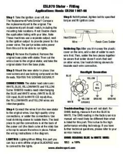
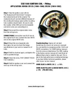
The Replacement Parts Similar? Compare ... Applications: Honda CR125 (1990-
1996) CR250 (1989-1992) ... in the factory service manual will most likely be.
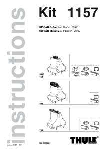
OPEL Vectra, 5-dr Hatchback, 89-95, 96-01. SAAB 9000 ... instructions. Kit XXXX
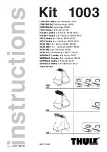
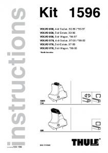
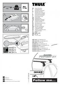
... 503-1003-02. 3. 1. 2. A. B. C. 750. 480. 480R /754. 480R /754. 480. 750 ....
www.thule.com [email protected][email protected] i i i. B. A. A. B. A. B.
B.
(please read combine harvester manufacturer instruction book). 2 - There is no ...
Example of fitting of the belt on to a New Holland TX Combine. Belt list in ...
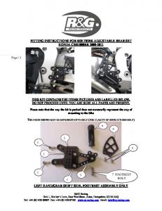
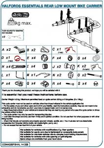
HONDA CBR1000RR 2008-2011. THIS KIT CONTAINS THE ITEMS PICTURED
AND LABELLED BELOW. DO NOT PROCEED UNTIL YOU ARE SURE ALL ...
It is essential that you read these instructions before use. .... It is the user´s
responsibility to comply with the standards applying in each country .... C CLASS.
85 -> 95. X. URBAN CRUISER. 09 -> 10. X. C8. 02 -> 11. X. VITO ... PEUGEOT.
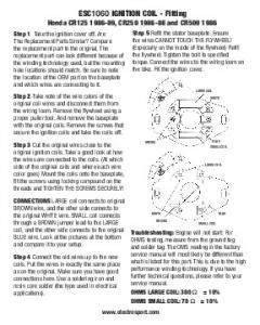
The Replacement Parts Similar? Compare ... Honda CR125 1986-89, CR250
1986-88 and CR500 1986 ... service manual will most likely be different than.
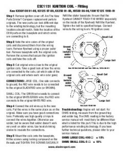
Compare replacement parts to originals. The new ... Kaw KX80/100 81-88,
KX125 87-88, KX250 81-88, KX500 86-98, YAM YZ125 1990-91 www.
electrosport. ... service manual will most likely be different than ... Kawasaki KX80
/100. Ground.
We take the question of customer service seriously. ... aided by Daryl Showering and for the shower system (including th
instructions. 1596. Kit. 480 ... VOLVO S70, 4-dr Sedan, 97-00 / *98-00. VOLVO ....
S. Dra åt växelvis. FIN. Kierrä vuorotellen. EST. Pinguldage vaheldumisi. LAT.
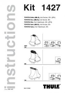
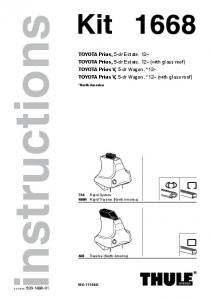
TOYOTA Prius, 5-dr Estate, 12– (with glass roof). TOYOTA Prius V, 5-dr Wagon, *
12–. TOYOTA Prius V, 5-dr Wagon, *12– (with glass roof). *North America. 1668.
The Replacement Parts Similar? Compare the replacement part to ... Applications
: Honda CR250 1997-98 ... The OMS reading in the factory service manual will ...
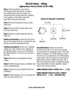
The Replacement Parts Similar? Compare ... Applications: Honda CR250 (1993-
1996) ... in the factory service manual will most likely be different than what is ...
The Replacement Parts Similar? ... specifications in your service manual for all
bolts. ... APPLCIATION: HONDA CR125 (1990-1996) CR250 (1989-1992).
This vehicle speed sensor puts out a signal that is for use with 60103 and 60203
kits. 1. Connect one wire from the sensor to the purple wire from the (TPI) kit that
is labeled VSS. 2. Connect the ... puts out an AC signal. 60116.doc. 02/13/1998.
50-8153. Panhard Rod Fitting Instructions. Removing Original Panhard Rod: 1.
Raise rear of vehicle and support axle housing on safety stands. 2. Undo the nut
...
Fitting. Instructions. TOWBAR. For Honda FR-V. 2004 -. HN58Q. MATERIALS. A.
1. Cross Bar. C. 1. Left Sidearm. D. 1. Right Sidearm. F. 2. Bush 31 O.D, 22mm ...
75 kg. 40. 0. 130 km/h. 80. 812•4DF/8. /501-3025-06. GB. Fitting instructions. D ...
Instructions de montage. NL. Montage- ... RU. Инструкции по установке. CZ. Nแ
vod na montแž. SK. Nแvod na montแž ... OPEL Astra GTC, 3-dr Hatchback, 05–.
caliper and also where the rotor will pass over the sensor. See Figure A ... Figure
B. Step 3. The brake caliper must be removed to install the sensor and to.
Read these instructions completely Step 1. Position the sensor loose fitting it to the front brake caliper. It is important to see the alignment location for the sensor to the brake caliper and also where the rotor will pass over the sensor. See Figure A
Note: This sequence shows how you slide and test fit the brake caliper rotor sensor into position. Be sure to double check the position and how the rotor sensor magnet will pass over the caliper sensor.
Figure A Step 2. The speedometer magnet sensor on the rotor, passes over the caliper mounted sensor providing the pick-up signal to the speedometer. After you have defined the location of the rotor sensor, you will need to scribe a location on the rotor using a marker. Repeat this visual inspection for the brake caliper mounted sensor double checking the alignment of the sensors and scribe or indicate a position reference mark on the caliper. See Figure B. 1/8" Dia. Drilled Hole Reference Marks
Figure C IMPORTANT NOTE: if you need to use just the magnet, then you will need to glue it onto the rotor, the kit comes with two bolts one of which is a replacement for a rotor bolt, and then a small round magnet Step 4. As most rotor shapes differ from manufacture to manufacture it is critical to insure the proper location of the rotor magnet before you adhering the magnet to the rotor. Be sure to double check this before proceeding. As shown in Figure C. Once you have confirmed this, you may find that you can simply replace one of the rotor mounting bolts with the supplied magnet rotor bolt. Depending on your set-up either use the rotor mounting bolt location or glue the "Flat" magnet in place. Do not over tighten the rotor mounting magnet bolt. 10 ft-lb is the standard specification. Step 5. After you have finished mounting both sensors, reattach the brake caliper and check the magnet pass-over clearance. If your alignment and positions are correct, tighten down everything to the torque settings provided in your service manual. Continue by installing your AceWell speedometer and attaching your sensor cable!
Figure B Step 3. The brake caliper must be removed to install the sensor and to make the installation easier. Position the sensor on your marks similar to the position shown in Figure B. With the sensor firmly held in place, insert a marker through the mounting holes on the sensor and mark the drill hole locations. Remove the sensor and drill a 1/8" hole through the caliper mount. It is suggested to use a new drill bit during this procedure. Attach the sensor to the caliper with the screws provided.