sistem kemudi aktif untuk model kereta separuh. Kawalan ... Prestasi pengawal
yang diperkenalkan dianalisis dengan pengawal jenis pengatur kuadratik linear.
ACTIVE STEERING FOR VEHICLE SYSTEM USING SLIDING MODE CONTROL
NOR MANIHA BTE ABD GHANI
A project report submitted in partial fulfilment of the requirements for a award of the degree of Master of Engineering ( Electrical-Mechatronics and Automatic Control)
Faculty of Electrical Engineering Universiti Teknologi Malaysia
PERFU'JTAKAAN KOEJ UNIVERSITI KEJURUTERAAN & TEKNOLOGI MALAYSIA No. Perolehen No. P&iggilan
Tankh
W;3 13 JUN 2006
MAY 2006
vi
ABSTRACT
The objectives of this thesis are to present a modeling and control of a singletrack car model for active steering vehicle system. The sliding mode control strategy will be utilized to overcome various coefficients of road frictions and external disturbances on the system. In order to compensate the disturbances, side slip angles and yaw rate of the vehicle will be observed. The model presented take into account different friction of road coefficients of the system. From the mathematical derivation it is found that the system has fulfilled a matching condition. Extensive computer simulations are performed for various types of disturbances such as crosswind and braking torque. From the simulation results the effect of disturbance attenuation will be observed. The performance of the proposed controller will be compared to the linear quadratic regulator and pole placement techniques. The results showed that the sliding mode control scheme is effectively in attenuating various disturbances for different road coefficients as compared to the LQR and pole placement control schemes. Furthermore, the simulation results also showed that the system is insensitive to the external disturbances and capable to overcome 'late action' by the driver due to sudden disturbance on any road conditions.
vii
ABSTRAK
Tesis mi bertujuan untuk memperkenalkan model matematik dan teknik kawalan sistem kemudi aktif untuk model kereta separuh. Kawalan ragam gelincir digunakan untuk mengatasi masalah pelbagai nilai pekali geseran jalan dan gangguan luar yang bertindak ke atas sistem. Oleh itu, untuk mengatasi masalah gangguan mi, gelinciran sisi dan kadar golengan sistem mi akan dikenalpasti. Sistem kawalan mi dipilih sebagai strategi kawalan untuk memperbaiki pelbagai pekali geseran jalan dan gangguan luar yang bertindak ke atas sistem. Daripada model matematik, sistem mi didapati memenuhi keadaan terpadan. Penyelakuan computer telah dijalankan dan didapati masalah gangguan luar yang berbeza dapat diatasi seperti angin lintang dan daya brek. Prestasi pengawal yang diperkenalkan dianalisis dengan pengawal jenis pengatur kuadratik linear dan penempatan kutub. Keputusan yang diperolehi menunjukkan pengawal yang dicadangkan berupaya memperbaiki gangguan luar pada pekali jalan yang berbeza jika dibandingkan dengan pengawal lain. Keputusan juga menunjukkan bahawa sistem mi tidak lagi sensitif kepada gangguan luaran dan berupaya mengatasi kesan lengah daripada pemandu hasil daripada gangguan mengejut pada semua permukaan jalan.
viii
TABLE OF CONTENTS
CHAPTER
TITLE
DECLARATION DEDICATION
ACKNOWLEDGEMENT PUBLICATION ABSTRACT ABSTRAK TABLE OF CONTENTS LIST OF TABLES LIST OF FIGURES LIST OF SYMBOLS
11 111
LIST OF ABBREVIATIONS
1
PAGE
iv V
vi vii viii xi xii xv
xvii
INTRODUCTION
1.1
Vehicle Stability
1
1.2
Project Overview
3
1.3
Objective of Study
4
ix
2
1.4
Scope of Project
5
1.5
Research Methodology
6
1.6
Literature Review
8
1.7
Layout of Thesis
11
SYSTEM MODEL
2.1
Introduction
12
2.2
Mathematical Modeling For A Single TrackModel
12
2.3
Linearization for Constant Velocity and Small Angles
18
2.4
Disturbance Profiles
22
2.4.1
Disturbance Profile 1
22
2.4.2
Disturbance Profile 2
22
2.5
3
24
SLIDING MODE CONTROL 3.1
Introduction
25
3.2
Overview on Sliding Mode Control
26
3.2.1
Sliding Mode Control Design
27
3.2.2
Switching Surface Design
29
3.2.3
Stability during Sliding Mode
30
3.2.4
Controller design
32
3.3
4
Conclusion
Conclusion
37
SIMULATION 4.1
Simulations
37
4.2
Results and Discussion
IN
4.2.1 Performance of SMC on Various Disturbance Profiles
40
4.2.2 An active steering system on wet road
41
4.2.3 An active steering system on dry road
46
4.2.4 Effect of the Reaching Mode Condition on Varying Sliding Gain, p
52
4.2.5 Effect on varying the value of boundary layer thickness, 6
4.3
5
Conclusion
62
71
CONCLUSION AND SUGGESTIONS
5.1
Conclusion
72
5.2
Suggestion For Future Research
73
REFERENCES
74
xi
LIST OF TABLES
TABLE
2.1
TITLE
PAGE
Parameter value for the active steering car system (BMW 735i)
21
xli
LIST OFFIGURES
FIGURE
TITLE
PAGE
1.1
Research methodology flow chart
6
2.1
Vehicle axis system
13
2.2
Feedback controlled additive steering angle 5 c
13
2.3
Single-track model for car steering
14
2.4
Lateral forces FyfF at the front wheel in tire coordinates and FF in chassis coordinates.
16
2.5
Disturbance profile 1 represented a braking torque
23
2.6
Disturbance profile 2 represented a crosswind
23
4.1
Sliding surface for DP
42
4.2
Control Input for DP
43
4.3
Side Slip angle for DPI
43
4.4
Yaw rate for DP
44
4.5
Control input for DP2
44
4.6
Phase portrait for DP2
45
4.7
Side Slip angle for DP2
45
4.8
Yaw rate for DP2
46
4.9
Sliding Surface for . DPI
47
4.10
Control input for DP
48
4.11
Side Slip angle for DP
48
4.12
Yaw rate for DPl
49
4.13
Sliding Surface for DP2
49
xlii 4.14
Control input for DP2
50
4.15
Side Slip angle for DP
50
4.16
Yaw rate for DP2
51
4.17
Sliding surface for positive sliding gain (DPI)
54
4.18
Sliding surface for negative sliding gain (DP 1)
54
4.19
Sliding surface for positive sliding gain (DP2)
55
4.20
Sliding surface for negative sliding gain (DP2)
55
4.21
Side slip angle for positive sliding gain (DP 1)
56
4.22
Side slip angle for positive sliding gain (DP 1)
56
4.23
Yaw rate for positive sliding gain (DP I)
57
4.24
Yaw rate for negative sliding gain (DP 1)
57
4.25
Control Input for positive sliding gain (DP 1)
58
4.26
Control Input for negative sliding gain (DP 1)
58
4.27
Side slip angle for positive sliding gain (DP2)
59
4.28
Side slip angle for negative sliding gain (DP2)
59
4.29
Yaw rate for positive sliding gain (DP2)
60
4.30
Yaw rate for negative sliding gain (DP2)
60
4.31
Control Input for positive sliding gain (DP2)
61
4.32
Control Input for negative sliding gain (DP2)
61
4.33
Sideslip angle for case 1 (DP 1)
63
4.34
Side slip angle for case 2 (DP 1)
63
4.35
Yaw rate for case 1 (DP 1)
64
4.36
Yaw rate for case 2 (DP 1)
64
4.37
Control input for case 1 (DP 1)
65
4.38
Control input for case 2 (DP 1)
65
4.39
Sliding surface for case 1 (DPi)
66
4.40
Sliding surface for case 2 (DPi)
66
4.41
Side slip angle for case 1 (DP2)
67
4.42
Side slip angle for case 2 (DP2)
67
4.43
Yaw rate for case 1 (DP2)
68
4.44
Yaw rate for case 2 (DP2)
68
xiv 4.45
Control Input for case 1 (DP2)
69
4.46
Control Input for case 2 (DP2)
69
4.47
Sliding surface for case 1 (DP2)
70
4.48
Sliding surface for case 2 (DP2)
70
xv
LIST OF SYMBOLS
aF
-
Sideslip angles at front tire
aR
-
Sideslip angles at rear tire
fip
-
Front chassis sideslip angle
fIR
-
Rear chassis sideslip angle
CF
-
Front cornering stiffness
CR
-
Rear cornering stiffness
(5p
-
Front steering angle
-
Rear steering angle
F,F
-
Lateral force at front tire
FY ,R
-
Lateral force at rear tire
-
Distance between the center of gravity (CG) and the front axle
EyE
-
Dominant component in chassis coordinates for front tire
FR
-
Dominant component in chassis coordinates for rear tire
tR
-
Distance between the center of gravity (CG) and the rear axle
F
-
longitudinal force component
J
-
Moment of inertia for the car body
M
-
Mass of the car body
V
-
Velocity of the car
IvI:D
-
Disturbances
P
- Coefficient of road friction
xvi U (t)
-
Sliding surface for a single track model
P
-
Sliding gain for a single track model
- Boundary layer thickness for a single track model
fi
-
r
- Yaw rate
S
-
Side slip angle
Generalized sliding surface
xvii
LIST OF ABBREVIATIONS
LSF
Linear State Feedback
DOF
Degree of Freedom
LQR
Linear Quadratic Regulator
VSC
Variable Structure Control
SMC
Sliding Mode Control
MRAC
Model Reference Adaptive Control
CHAPTER 1
INTRODUCTION
1.1
Vehicle stability
Vehicle handling is essentially the response provided by the vehicle due to forces that act on it. For example, driver steering, wind, degree of horizontal curvature and vehicle suspension affect the handling characteristic and destabilized a vehicle. The performance of the vehicle stability system has been greatly increased due to increasing vehicle capabilities. This include active suspension system and active steering system in order to stabilize a vehicle.
A new generation of stability control systems help the driver and passengers to maintain ride comfort and safety. A stability control system goes one step further by actually detecting when a driver has lost some degree of control. It then automatically stabilize the vehicle to help the driver regain control back.
2 The investigation of vehicle suspension system are much interested in recent years and it promised some comfort issue. Steering control for vehicle motion is crucial for vehicle safety. The goal of this research is concentrated on active steering for vehicle system. The basic problems associated with vehicle handling are subject to the vehicle desired path and vehicle stabilization on this path.
Vehicle handling and ride characteristics combined with the mechanics of roadtire interaction greatly influence the vehicle stability. Finally, to ensure the vehicle stability, all four tires must remain contact with the road surface. The associated friction between the mediums is also plays a role in the vehicle handling and ultimately ride experience.
Even on a 'good' road, sudden movement of the steering could make a car skid will caused a critical driving situation. For example, a child crossing the road unexpectedly will force the driver to an evasive action. The inexperienced driver who caught in this kind of situation is easily overreact and destabilizes the car.
A skid normally occurs when the speed of the car is too fast for the normal road conditions. A skid hardly ever occurs at a slow speed. Severe braking can also cause a skid. Many dangerous situations occurred on the roads because a car driver does not react fast enough at the beginning of skidding or rollover. Automatic feedback systems can assist the driver to overcome such dangerous situations. A further step is automatic driving by following a lane reference. In both cases, robustness of the control system with respect to the uncertain road-tire contact is very important. Further uncertain parameters may be due to the vehicle mass, velocity and acceleration, slip-angle and Yaw angle.
1.2
Project Overview
The existing driver assistant systems use a braking system that been applied on the individual wheels [1]. These systems are cheap, because the hardware consists of the existing ABS braking system with an additional yaw rate sensor and do not require a new actuator.
There are few reasons why an actuator is needed in the new design of the driver assistant system. The first reason is to generate torque that be able to compensate yaw disturbance torques. Torques is tire force times lever arm. Then, the second reason is that different friction coefficient ji on the left and right sides (u-split braking) may be the cause of the disturbance torque. In contrast, a steering torque can compensate the braking torque and achieve a straight short braking path. A third reason for driver assistance by steering (rather than by braking) is energy conservation, reduced wear of tires and brakes and smooth operation around zero correction.
Practically, braking systems cannot immediately compensate small errors, but it have to intervene relatively late in detected emergency situations when the car is close to skidding and the driver is unpleasantly surprised by the intervention. Only the steering systems are feasible for continuous operation. Also for better comfort under continuous disturbances.
It is well known that vehicle dynamics are subjected to various uncertainties due to modelling inaccuracies [3]. Thus, conventional linear control approaches is not capable to handle this situation. Therefore, the robust performance capabilities against uncertainties may be overcome by applying a robust controller to the vehicle system design.
El The aim of this study is to address the automatic steering control of passenger cars for general lane-following manoeuvres. A lateral vehicle control system using a 2DOF controller based on H loop-shaping methodology is successfully designed [3]. This robust controller provides good lane-keeping and lane-change abilities on both curved and straight road segments. Furthermore, it offers a computationally efficient algorithm and does not require explicit knowledge of the vehicle uncertainty. However, the test results demonstrate that higher vehicle speed has a destabilizing effect on the vehicle system.
1.3
Objective of study
The objectives of this research are as follows: I.
To establish a single-track car model.,
II.
To develop a controller that base on the robust control strategy that will overcome uncertainties and disturbances of a road handling that will prevent the car skidding problem.
III.
To evaluate and analyzed the performance of the system with a proposed controller.
To achieve these objectives various parameters such as tire slip angle and yaw rate will be observed by using the computer simulations. Performance of the proposed Controller will be compared to LQR and Sliding Mode Control techniques.
in The aim of this study is to address the automatic steering control of passenger cars for general lane-following manoeuvres. A lateral vehicle control system using a 2DOF controller based on H loop-shaping methodology is successfully designed [3]. This robust controller provides good lane-keeping and lane-change abilities on both curved and straight road segments. Furthermore, it offers a computationally efficient algorithm and does not require explicit knowledge of the vehicle uncertainty. However, the test results demonstrate that higher vehicle speed has a destabilizing effect on the vehicle system.
1.3
Objective of study
The objectives of this research are as follows:
To establish a single-track car model. II.
To develop a controller that base on the robust control strategy that will overcome uncertainties and disturbances of a road handling that will prevent the car skidding problem.
III.
To evaluate and analyzed the performance of the system with a proposed controller.
To achieve these objectives various parameters such as tire slip angle and yaw rate will be observed by using the computer simulations. Performance of the proposed controller will be compared to LQR and Sliding Mode Control techniques.
5
Theoretical verification of the proposed controller on its stability and rechability will be accomplished by using a Lyapunov's second method theory. The performance of the active steering system will be observed by using extensive computer simulation that will be performed using MATLAB software and SIMULINK Toolbox subjected to various types of parameter.
1.4
Scope of Project
The work undertaken in this project are limited to the following aspects: I.
Mathematical establishment of a single track car model as described by Ackermann J. et all.
II.
An active car steering system is evaluated on straight road due to various disturbance profiles and coefficient of road friction.
III.
Design a controller for a single track car model using sliding mode control technique to compensate disturbances.
IV.
Perform a simulation works by using a MATLAB/Simulink to observe effectiveness and robustness of the controller.
V.
Compare the performance of the proposed SMC with pole placement and Linear Quadratic Regulator (LQR) techniques.
1.5
Research Methodology
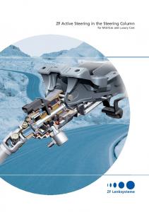
The methodology of this research is shown in the flow chart in Figure 1.1 below:-
Literature study
I
[ Mastering in simulation tools I
Research on active car steering
Identify various parameter
I
I
Control strategy-LQR, SMC
Establish mathematical model
Design Controller
Comparison between SMC, pole placement and LQR
Evaluate and verification controllers using MATLAB
End
Figure 1.1
Research methodology flow chart
7 In the beginning, there are two tasks that need to be done simultaneously. Besides of doing literature review, exercises and tutorials need to be done for mastering the simulations tools and some preliminary simulations need to be carried out as well.
Then, the problem of this research will be stressed on a car manoeuvres on straight road due to various disturbances and coefficient of road friction to ensure stability and prevent skidding. The task is to remain the car at the centerline planned lane as accurately as possible with the changes of disturbances. This will be considered of the dynamics relationship of a car and take into account the yaw movement and lateral motion that make the car unstable.
Thus, the steering control strategy is required to minimize the lateral displacement, lateral acceleration and yaw rate error due to step changes in disturbances. Various parameters will be observed such as relationship between slip angles and lateral forces on tire and uncertainties on the friction of the road surfaces.
After the preliminary research, the mathematical model will be established for lane-keeping manoeuvres (straight path). First, the state space representation of the dynamic model of the car with forces input will be outlined. Based on the dynamic models of the actuators, the state space representation of the active steering car will be derived. Finally the effect of the disturbance torque as an undesired yaw rate that should be compensated by an automatic control system will be presented.
Then, new control strategy for active steering car system will be proposed based on the sliding mode control approach. The design of the sliding mode control which consists of selecting the sliding surfaces and the controller will be discussed. Various types of the sliding surfaces are outlined. Several types of controllers that drive the state
trajectory onto the sliding surface will be presented. The applications of sliding mode control in control engineering world will be clarified to show the importance of the sliding mode control strategy and applicability.
The sliding mode controller is proposed to improve the performance of the ride comfort and road handling characteristic of the car steering system. To assure the robustness of the proposed controller, various disturbances and coefficient of road friction will be applied to the system. The chattering and boundary layer effect on the controller will also be outlined by varying the parameters in the continuous switching gain.
Finally, the proposed controller will be evaluated with extensive simulation work to determine the performance. Then, the performance of the system using SMC will be compared with pole placement and Linear Quadratic Regulator (LQR) techniques. The results will be verified and analyzed in time domain related to disturbance attenuation such as reduce in magnitude, overshoot, rise time and settling time.
1.6
Literature Review
In the past years, various control strategies have been proposed by researchers to improve the vehicle stability in the presence of parameter variations of the vehicles. These control strategies may be grouped into techniques and approaches how it will be used. In the following, some of these control approaches that have been reported in the literature will be briefly presented.
Most of the approaches have assumed a linearized model in the design and do not consider nonlinearity of the tire characteristics. These approaches may yields good results as long as the vehicle, remains within the linear region of the tire characteristics. However the controller may even worsen the driving situation drastically compared to conventional vehicle, as soon as the nonlinear region of the tire characteristics is entered [4]. Therefore, vehicle stability system has to be designed and taking into account the uncertain and nonlinear tire characteristics which are determined by the road-tirecontact.
A robust decoupling of car steering dynamics with arbitrary mass distribution is presented [2]. The restrictive mass distribution assumption is abandoned and a generalized decoupling control law for arbitrary mass distribution has been derived. The result of this paper provides an interface between the modelling of the steering dynamics of a single car by two masses and the higher level control problems of automatic steering and distance keeping of single mass models in a platoon of cars. However, there are some restrictive assumption in this paper which is the constant velocity, small sideslip and steering angles.
H control approach is proposed to overcome robust stabilization and uncertain plants [6]. A linear matrix inequalities based on H. methodology has been designed [7] Then Hoo loop-shaping design procedure was proposed [8]. The results showed that this method provides a computationally efficient algorithm and does not require explicit knowledge of the uncertainty.
The combination of H. loop shaping and 2-DOF has been reported in [3] [7] to achieve high performance control system for vehicle handling. It has been shown that this algorithm allowed separate processing of the robust stabilization problem and reference signals. The test results the robust control scheme offers a computationally
10 efficient method and does not require explicit knowledge of the vehicle uncertainty. The presented system exhibits the required performances and robustness properties under parameter variations while maintaining passenger comfort. However, the test results demonstrate that higher vehicle speed has a destabilizing effect on the vehicle system.
A model reference adaptive control (MRAC) technique of 2WS cars which is realized by steer-by-wire technology has been reported [9]. The aim of MRAC is to make the output of varies parameter asymptotically approach the output of a user defined reference model that represents a desired characteristics. The study introduce first-order system whose output is D*, defined as the combination of yaw rate and lateral acceleration. This method can treat the nonlinear relationships between the slip angles and the lateral forces on tires, and the uncertainties on the friction of the road surface.
Recently, intelligent based techniques such as fuzzy logic, neural network and genetic algorithm have been applied to the active steering system [10]. The papers presented a fuzzy-rule-based cornering force estimator to avoid using an uncertain highly nonlinear expression, and neural network compensator is additionally utilized for the estimator to correctly find cornering force. The result indicated that the proposed control system is robust against the uncertainty in vehicle dynamic model disturbances such as a side wind gust and road conditions.
A fuzzy logic controller with Hardware-In-the-Loop Simulation (HILS) simulator has been proposed by [11] to evaluate the performance-of the system on a slippery road. HILS simulator is composed of hardware (steering wheel) and software (vehicle simulation tool and steering control system). This method used fuzzication, fuzzy inference and defuzzication technique. It can be observed that this controller able to maintain the steering maneuverability on slippery road and very useful to correct the vehicle's route when the vehicle's direction is biased due to side wind or obstacles.