Kalaivani Rajagopal et al. / International Journal of Engineering and Technology (IJET)
MULTI OBJECTIVE OPTIMIZATION OF VEHICLE ACTIVE SUSPENSION SYSTEM USING DEBBO BASED PID CONTROLLER Kalaivani Rajagopal #1, Lakshmi Ponnusamy#2 #
DEEE, CEG, Anna University Chennai, India 1
[email protected] 2 lakshmi_
[email protected] Abstract—This paper proposes the Multi Objective Optimization (MOO) of Vehicle Active Suspension System (VASS) with a hybrid Differential Evolution (DE) based Biogeography-Based Optimization (BBO) (DEBBO) for the parameter tuning of Proportional Integral Derivative (PID) controller. Initially a conventional PID controller, secondly a BBO, an rising nature enthused global optimization procedure based on the study of the ecological distribution of biological organisms and a hybridized DEBBO algorithm which inherits the behaviours of BBO and DE have been used to find the tuning parameters of the PID controller to improve the performance of VASS by considering a MOO function as the performance index. Simulations of passive system, active system having PID controller with and without optimizations have been performed by considering dual and triple bump kind of road disturbances in MATLAB/Simulink environment. The simulation results show the effectiveness of DEBBO based PID (DEBBOPID) in achieving the goal. Keyword-Vehicle Active Suspension System, Multi Objective Optimization, Biogeography Based Optimization (BBO), Differential Evolution (DE) based BBO (DEBBO), Simulation I. INTRODUCTION It is a very essential and great challenging task to the automobile industries to provide good travelling comfort to the passengers. The vibration of vehicle body can cause unwanted noise in the vehicle, damage to the fittings attached to the car and severe health problems such as increase in heart rate, spinal problems etc. to the passengers. The research and development sections of the automobile industries hence promote the research on vibration control. The Vehicle Active Suspension System (VASS) has been concentrated by academicians also as the problem is open to all. For vehicle handling and ride comfort, the suspension system of an automobile plays an important role. Vehicle handling depends on the force acting between the road surface and the wheels. The ride comfort is related to vehicle motion sensed by the passenger. To improve the handling and ride comfort performance, in preference to conventional passive system, semi-active and active systems are being developed. Passive system uses static spring and damper where as a semi-active suspension involves the use of dampers with variable gain. On the other hand, an active suspension involves the passive components augmented by actuators that supply additional forces and possesses the ability to reduce the acceleration of sprung mass continuously as well as to minimize suspension deflection which results in the improvement of tyre grip with the road surface [1, 2]. In an active suspension the actuator force is generated by a hydraulic or pneumatic actuator which is controlled by a controller. In the past, most researchers concentrate on different control strategies and improving the performance of a particular control strategy by using different control structures. Some researchers discussed about several control approaches hypothetically, simulated with simulation software, confirmed practically and proposed for the control of active suspension system. Optimal control [3] places a vital role among the control schemes. The comparison of Linear Matrix Inequality (LMI) based controller and optimal Proportional Integral Derivative (PID) controller by Abdalla et al. [4] proved the sprung mass displacement response improvement by LMI controller with only the suspension stroke as the feedback. Design of PID controller is discussed in [4, 5] and [6]. Design of robust PI controller which is used to obtain optimal control is presented in [7]. There are various classical well defined methods of tuning the PID parameters. Also there are many evolutionary algorithms and intelligent approaches to tune the PID parameters. Mouleeswaran Senthil kumar [8] used the Zeigler- Nichols method of tuning for PID controller applied to VASS. Wen Dingdu designed a PID, in which the parameters are tuned with Fuzzy reasoning method [9]. In [10], for a flow process, to control the flow rate and to maintain the desired set point, PID tuning parameters is tuned with firefly algorithm. Two LBests Multi-Objective Particle Swarm Optimization [11] (2LB-MOPSO) is applied to design multi-objective robust
ISSN : 0975-4024
Vol 6 No 1 Feb-Mar 2014
252
Kalaivani Rajagopal et al. / International Journal of Engineering and Technology (IJET)
PID controllers for F18/HARV fighter aircraft system. Tuning of the PID controller parameter using Bacteria Foraging (BF) based Internal Model Control (IMC) [12] is proved to be effective than the Genetic Algorithm (GA) based IMC. After the introduction of Biogeography-Based Optimization (BBO) by Dan Simon [13], it is proven to be the best with some bench mark functions as well as real time problems when compared to other Evolutionary Algorithms (EAs) [14-23]. Hybridization of EAs is growingly getting popular among the optimization techniques owing to their ability in handling the real world problems [24]. The hybrid DEBBO algorithm which combines the exploration of DE with the exploitation of BBO effectively is proposed by Wenyin in [25], tested with various benchmark functions and proved with experimental results, that it is very effective. The concept is also applied for an economic load dispatch problem [26, 27] and optimal power allocation in wireless sensor networks [28] and proved to be more effective. In this paper an attempt is made to check the suitability of DEBBO for the tuning of PID controller parameters by achieving Multi Objective Optimization (MOO) in a VASS when subjected to road disturbances. Organization of the paper is as follows. First the control structure and schemes for MOO of a Quarter Car (QC) model of VASS are presented. Then the simulation results are shown and discussed. Finally concluded with the observations of this work. II. CONTROL STRUCTURE AND SCHEMES Road disturbance input
PID3 PID2
+
+
Fa G4
PID1
Ga
zs QC Model
Body Acceleration G1 Suspension Deflection
G2 G3
Tyre Deflection
Fig. 1.The block diagram representation of control structure of VASS using PID controller
The control structure for the QC model [29] considered in this study is shown in Fig. 1. Three system responses such as body acceleration, suspension deflection and tyre deflection (with magnitude of feedback gains G1=1, G2=3 and G3=2respectively) are feedback which are needed to be minimized for a vehicle so that the actuator force required is less to provide the control action. The output control signals are amplified by a gain G4 =3 and then given as the input to the actuator. In this work the nonlinear dynamics of actuator is not considered and the gain of the linear actuator is taken as Ga. The actuator force Fa which is the additional input to the system is proportional to the controller output to have better comfort. A. PID Controller Most of the automated industrial processes include a PID controller which is a combination of proportional, integral and derivative controller that can improve both the transient and steady state performance of the system. Mathematical representation of simple PID control scheme is given by
Gc = kpe(t) + ki e(t)dt + kd
de dt
(1)
where G c is the controller output
kp
proportional gain
ki
integral gain
kd
differential gain
e(t)
input to the controller
e(t)dt
time integral of the input signal
de dt
time derivative of the input signal
ISSN : 0975-4024
Vol 6 No 1 Feb-Mar 2014
253
Kalaivani Rajagopal et al. / International Journal of Engineering and Technology (IJET)
Autotuning for PID1, PID2 and PID3 has been carried out using robust response tuning method with the MATLAB simulation software. B. Optimization of PID Controller In this work BBO and hybrid DEBBO techniques are used to find the PID tuning parameters such as kp, ki and kd of all the PID1, PID2 and PID3 controllers to minimize the MOO function J given by (2). 2
J lim (a1zs a2 ( zs zu )2 a3 ( zu zr )2 ))dt T
(2)
where a1=1, a2=100 and a3=120 are the random numbers used as the weighting factor of the three feedback signals body acceleration, suspension deflection and tyre deflection respectively. T is the time period in seconds. 1) Biogeography based PID Controller: A population based BBO technique has been developed based on the theory of Biogeography [13] which describes how species voyage from one habitat to other, how new species come up and species become vanished. A habitat is a geographically isolated island from other habitats. Each habitat has its individual features which are specified by the Habitat Suitability Index (HSI) variables. A habitat with high HSI is well suited for species living. The migration of a species among habitats takes place when the high HSI habitats have more species or habitat has low HSI. This process is known as emigration. Another process called immigration takes place when the species move towards the habitat with high HSI having few species. The emigration and immigration of species from a habitat are called migration. The emigration rate (µ) and immigration rate (λ) vary with the number of species available in the habitat. With no species the immigration rate touches the upper limit and with maximum number of species it is zero whereas the emigration rate increases with increase in the number of species. The change in HSI due to natural disaster is taken into account with the mutation operation. The optimization steps of BBO algorithm [22] are described as follows: 1. Initialize the optimization problem, the BBO parameters and the habitats. 2. Perform BBO operations such as migration and mutation. 3. Modify the habitats. 4. Check the stopping criteria; if not achieved, repeat from step 2. BBO does not involve the reproduction of solution as in GA. In each generation, the fitness of every solution (habitat) is used to find the migration rates. For the BBO based PID (BBOPID) controller, the following parameters are initialized: population size, the maximum species count (Smax), maximum emigration rate (E), maximum immigration rate (I), maximum mutation rate (mmax), habitat modification probability (Pmod), number of decision variables, the number of habitats, maximum number of generations, mutation probability, and migration probability. 1. The individual habitat variables are random initialized. 2. Mapping of HSI to the number of species S, calculation of the emigration rate and immigration rate using equations 3 and 4 are performed. λ = 1 (1 -
μ =
d ) S m ax
(3)
E×d S m ax
(4)
where d is the number of species at the instant of time. 3. The BBO operation migration is performed based on the definition 7 in [13] and the HSI is recomputed. 4. Then the mutation operation is performed as in definition 8 in [13] and the HIS is recomputed. The emigration and immigration rates of each solution are useful in probabilistically sharing the information between the habitats. Each solution can be modified with the habitat modification probability Pmod to yield good solution. 5. From step 2 the computation is repeated for next iteration. The loop is terminated after predefined number of generations or after achievement of acceptable solution. Parameter Initialization for BBO Modification probability =1 Mutation probability = 0.05 Selectiveness parameter δ =2 Max immigration rate =1
ISSN : 0975-4024
Vol 6 No 1 Feb-Mar 2014
254
Kalaivani Rajagopal et al. / International Journal of Engineering and Technology (IJET)
Max emigration rate =1 Step size used for numerical integration =1 Lower bound and Upper bound for immigration probability per gene Lower bound and Upper bound of tuning parameters
= [0.01, 1] = Table I
TABLE I Range of the PID Controller Tuning Parameters
Tuning Parameter kp1 ki1 kd1 kp2 ki2 kd2 kp3 ki3 kd3
Lower Bound 0 0 0 0 0 0 0 0 0
Upper Bound 0.1 10 0.5 10 5 1 1 1 1
2) Hybridization (DEBBO):BBO algorithm without hybridizing with any evolutionary algorithms not has much diversity in local or sub optimal solutions. In DEBBO, a hybrid migration operator of BBO is applied along with mutation, crossover and selection operators of DE which combines the searching of DE with the operation of BBO effectively to speed up the convergence property [26] and to find better quality results. Technically simple population based Differential Evolution (DE) algorithm [30] having self-organizing ability is suitable even for non-linear systems and can be used for continuous function optimization for tuning of PID controller parameters. Basic steps involved in DE algorithm are 1. Initialization 2. Evaluation 3. Repeat{ Mutation, Recombination, Evaluation, Selection}Until fitness function is minimized. (5) for each target vector
Generate the mutant vector , parameter vectors in the population. ,
, ,
. , 1, 2, … …
,
(5)
,
The real and constant scaling factor for differential variation The trial vector for crossover operation is ,
where
,
,
,
, , i=1, 2, 3…….N where N is the number of
……
,
0,2 (6)
,
, ,
1, 2, … … . . 0,1 is the crossover constant. where 0,1 is the jth evaluation of uniform random number and chosen index which ensures that
,
gets atleast one parameter from
,
(7)
1,2, … …
randomly
.
The fitness criterion is used to decide whether the trial vector is a member of next generation or not. If the fitness value of the trial vector , is better than that of target vector , , then in next generation, target vector , is assigned to be , . Otherwise first generation value , is retained. Parameter Initialization for DEBBO BBO parameters : as listed before DE parameters : Scaling factor F= 0.5 Crossover constant CR= 0.5
ISSN : 0975-4024
Vol 6 No 1 Feb-Mar 2014
255
Kalaivani Rajagopal et al. / International Journal of Engineering and Technology (IJET)
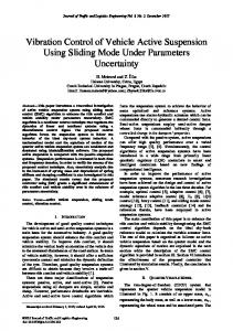
1 BBO DEBBO
0.9 0.8
Objective function value
0.7 0.6 0.5 0.4 0.3 0.2 0.1 0
0
10
20
30
40
50 Iterations
60
70
80
90
100
Fig. 2. Statistics of search Process
The optimization results are computed by averaging 20 minimization runs and the convergence characteristics of each technique are shown in Fig. 2. Each run yielded the global minimum results. From the convergence plot, DEBBO is found to be superior than BBO algorithm. III.SIMULATION All The parameters of the quarter car model taken from [29] are listed below Sprung mass ( ms) = 290 kg Unsprung mass ( mu) = 59 kg Damper coefficient ( bs) = 1,000 Ns/m Suspension stiffness ( ks) = 16,812 N/m Tyre stiffness ( kt) = 190,000 N/m 0.08
Road Input Amplitude (m)
0.07 0.06 0.05 0.04 0.03 0.02 0.01 0
0
0.5
1
1.5
2
2.5 Time (sec)
3
3.5
4
4.5
5
(a) 0.08
Road Input Amplitude (m)
0.07 0.06 0.05 0.04 0.03 0.02 0.01 0
0
0.5
1
1.5
2
2.5 Time (sec)
3
3.5
4
4.5
5
(b) Fig. 3. Road Input Profile
ISSN : 0975-4024
Vol 6 No 1 Feb-Mar 2014
256
Kalaivani Rajagopal et al. / International Journal of Engineering and Technology (IJET)
International Organization for Standardization gives the classification of road roughness using Power Spectral Density values. In this work dual and triple bump road disturbances which represent the speed breaker on the road (Fig. 3) is considered. TABLE II PID Controller Tuning Parameters
PID Parameters kp1 ki1 kd1 kp2 ki2 kd2 kp3 ki3 kd3
Robust response tuning 0.0103 0.415 0.0022 0.0898 1.56 0.0012 0.186 0.009 0.915
BBOPID
DEBBOPID
0.0029 0.7257 0.0018 0.8898 1.321 0.0025 0.177 0.0094 0.622
0.0075 0.397 0.0004 0.1 1.6214 0.0027 0.276 0.0089 0.99
0.05 Passive PID PIDBBO PIDDEBBO
Sprung Mass Displacement (m)
0.04 0.03 0.02 0.01 0 -0.01 -0.02 -0.03
0
0.5
1
1.5
2
2.5 Time (sec)
3
3.5
4
4.5
5
(a)Sprung Mass Displacement 5 Passive PID PIDBBO PIDDEBBO
4
2
Body Acceleration (m/sec )
3 2 1 0 -1 -2 -3 -4 -5
0
0.5
1
1.5
2
2.5 Time (sec)
3
3.5
4
4.5
5
(b) Body Acceleration
ISSN : 0975-4024
Vol 6 No 1 Feb-Mar 2014
257
Kalaivani Rajagopal et al. / International Journal of Engineering and Technology (IJET)
0.06 Passive PID PIDBBO PIDDEBBO
Suspension Deflection (m)
0.04 0.02 0 -0.02 -0.04 -0.06 -0.08
0
0.5
1
1.5
2
2.5 Time (sec)
3
3.5
4
4.5
5
(c ) Suspension Deflection x 10
8
-3
Passive PID PIDBBO PIDDEBBO
6 4 Tyre Deflection (m)
2 0 -2 -4 -6 -8 -10 -12
0
0.5
1
1.5
2
2.5 Time (sec)
3
3.5
4
4.5
5
(d) Tyre Deflection 1000 PID PIDBBO PIDDEBBO
Force (N)
500
0
-500
-1000
-1500
0
0.5
1
1.5
2
2.5 Time (sec)
3
3.5
4
4.5
5
(e) Control Force Fig. 4.Time responses with dual bump input 0.06 Passive PID PIDBBO PIDDEBBO
Sprung Mass Displacement (m)
0.05 0.04 0.03 0.02 0.01 0 -0.01 -0.02 -0.03
0
0.5
1
1.5
2
(a)
ISSN : 0975-4024
2.5 Time (sec)
3
3.5
4
4.5
5
Sprung Mass Displacement
Vol 6 No 1 Feb-Mar 2014
258
Kalaivani Rajagopal et al. / International Journal of Engineering and Technology (IJET)
5 Passive PID PIDBBO PIDDEBBO
4
2
Body Acceleration (m/sec )
3 2 1 0 -1 -2 -3 -4 -5
0
0.5
1
1.5
2
2.5 Time (sec)
3
3.5
4
4.5
5
(b) Body Acceleration 0.06 Passive PID PIDBBO PIDDEBBO
Suspension Deflection (m)
0.04 0.02 0 -0.02 -0.04 -0.06 -0.08
0
0.5
1
1.5
2
2.5 Time (sec)
3
3.5
4
4.5
5
(c) Suspension Deflection x 10
8
-3
Passive PID PIDBBO PIDDEBBO
6
Tyre Deflection (m)
4 2 0 -2 -4 -6 -8 -10 -12
0
0.5
1
1.5
2
2.5 Time (sec)
3
3.5
4
4.5
5
(d) Tyre Deflection 1000 PID PIDBBO PIDDEBBO
Force (N)
500
0
-500
-1000
-1500
0
0.5
1
1.5
2
2.5 Time (sec)
3
3.5
4
4.5
5
(e) Control Force Fig. 5.Time responses with triple bump input
ISSN : 0975-4024
Vol 6 No 1 Feb-Mar 2014
259
Kalaivani Rajagopal et al. / International Journal of Engineering and Technology (IJET)
The QC model [29] with the control schemes discussed are simulated with the two road input profiles.The PID tuning parameters obtained with robust response tuning, BBO and DEBBO with dual bump road input are listed in Table II. The simulation results of passive system, system with PID, BBO based PID (BBOPID)and DEBBO based PID (DEBBOPID) controllers are shown in Fig. 4 and 5. (a) - (d). Also the RMS values of the time responses of the system are tabulated in Table III and IV. It is clear from Fig. 4. (a) and Fig. 4. (b) that the sprung mass displacement and vehicle body acceleration is considerably reduced by the proposed DEBBOPID controller. It guarantees the travelling comfort to the passengers. Also Fig. 4. (c) shows that the suspension deflection with all the controllers are at most the same. Fig. 4. (d) illustrates the road holding ability maintained by all the controllers. Fig. 4. (e) shows the control force required for the control action to minimize the MOO problem. Robustness of the designed DEBBOPID controller is checked with triple bump road input. Sprung mass displacement (Fig. 5. (a) ) and body acceleration (Fig. 5. (b) ) are less with the DEBBOPID. The suspension deflection is merely same with all the controllers. The tyre deflection and the control force required are shown in Fig. 5. (d) and Fig. 5. (e). TABLE III RMS Values of the Time Responses of Quarter Car Model with Dual Bump Input
System
Passive PID BBOPID DEBBOPID
Sprung Mass Displacement x10-3 (m) 11.8 3.799 4.054 3.712
Body Acceleration x10-3(m/s2) 939.9 525.8 407.7 373.5
Suspension Deflection x10-3(m) 12.05 9.911 10.22 9.95
Tyre Displacement x10-3 (m) 1.716 0.9853 1.018 0.943
TABLE IV RMS Values of the Time Responses of Quarter Car Model with Triple Bump Input
System
Passive PID BBOPID DEBBOPID
Sprung Mass Displacement x10-3 (m) 20.3 7.876 7.935 7.715
Body Acceleration x10-3(m/s2) 1460 818 755.5 736.9
Suspension Deflection x10-3(m) 18.87 15.11 15.14 15.19
Tyre Displacement x10-3 (m) 2.678 1.556 1.531 1.486
10
Passive PID PIDBBO PIDDEBBO
0
2
-4
PSD of Body Acceleration (m sec /Hz)
From Table III and IV, it is clear that the VASS using DEBBOPID controller is used for betterment of ride and travelling comfort with reduced body acceleration over PID controller with and without BBO and passive system.
10
10
10
-2
-4
-6
2 Frequency (Hz)
4
6
8
10
12
14
(a)
ISSN : 0975-4024
Vol 6 No 1 Feb-Mar 2014
260
Kalaivani Rajagopal et al. / International Journal of Engineering and Technology (IJET)
10
1
Passive PID PIDBBO PIDDEBBO
0
2
-4
PSD of Body Acceleration (m sec /Hz)
10
10 10 10 10 10 10
-1
-2
-3
-4
-5
-6
10
1
Frequency (Hz)
(b) Fig. 6. PSD of body acceleration
In the evaluation of vehicle ride quality, the Power Spectral Density (PSD) for the body acceleration as a function of frequency is of prime interest and is plotted for passive and system with PID, BBOPID and DEBBOPID controller for the two different types of road inputs (Fig. 6). It is clear from the PSD plot that in the human sensitive frequency range 4-8 Hz, compared to PID and BBOPID, DEBBOPID reduces the vertical vibrations to a great extent and improves the comfort of travelling when subjected to road input. IV. CONCLUSION The Multiple Objective Optimization of PID tuning parameters for the application in QC model with linear actuator has been discussed in this paper. Among the two optimization techniques discussed, the DEBBO gives better performance. DEBBOPID results are good compared to passive system, conventional PID controller and BBOPID based VASS. DEBBOPID reduces the body acceleration considerably and ensures the travelling comfort to the passengers. The control schemes are easy to implement and with reference to the PSD of body acceleration, it is clear that all the controllers provides better vibration control compared to the passive system. DEBBOPID gives better PSD and is the best as it converges quickly compared to BBOPID for the minimization of multiple objectives of a vehicle. REFERENCES [1] [2] [3] [4] [5] [6] [7] [8] [9] [10] [11]
[12]
[13] [14] [15] [16] [17] [18]
Seok_il Son, Fuzzy Logic Controller for an Automotive Active suspension system, Master’s Thesis, Syracuse University, 1996. D. Hrovat, Survey of advanced suspension developments and related optimal control applications, Automatica, vol. 33, pp.171-181, 1997. D. Hrovart, Applications of optimal control to Dynamic advanced automotive suspension design, ASME J. of Dynamic Systems, Measurement and Control, (Special issue commemorating 50 years of the DSC division), vol. 115, pp.328-342, 1993. MO. Abdalla, N. Al Shabatat, and M. Al Qaisi, Linear matrix inequality based control of vehicle active suspension system, Vehicle System Dynamics, vol. 47, pp.121-134, 2007. K. Rajeswari, and P. Lakshmi, Vibration control of mechanical suspension system, Int. J. Instrumentation Technology, vol.1, pp. 60-71, 2011. O. Demir, Keskin and S. Cetlin, Modelling and control of a nonlinear half vehicle suspension system; A hybrid fuzzy logic approach, Nonlinear Dynamics, vol. 67, pp. 2139-2151, 2012. C. Yeroglu, , and N. Tan, Design of robust PI controller for vehicle suspension system, Journal of Electrical Engineering & Technology, vol. 3, pp.135-142, 2008. Mouleeswaran Senthil kumar, Development of Active Suspension System for Automobiles using PID Controller, Proceedings of the World Congress on Engineering 2008, WCE 2008, II, 2008. Wen Dingdu, Electric Furnace Control System Based on the Grey Prediction Fuzzy Adaptive Control, Sixth International Conference on Fuzzy Systems and Knowledge Discovery, pp. 86-90, 2009. D. Kumanan, and B. Nagaraj, Tuning of proportional integral derivative controller based on firefly algorithm, Systems Science & Control Engineering, vol.1, pp. 52–56, 2013. A. Jayachitra, R. Vinodha, and S. AbrahamLincon, Multi Objective Robust PID Controller Tuning For A Fighter Aircraft Using MOPSO, International Conference on Innovations in Intelligent Instrumentation, Optimization& Signal processing, ICIIIOS’13. pp. 1009-1014, 2013. U.SaburaBanu, S. K. LakshmanaPrabu, K. Sugandhan, and Abdul Wahid Nasir, Tuning Of PID Controller Using Bacteria Foraging Based Internal Model Control, International Conference on Innovations in Intelligent Instrumentation, Optimization & Signal processing, pp. 2535-2539, 2013. Dan Simon, Biogeography based optimization, IEEE Transactions on Evolutionary Computation, vol.12, pp. 702-713, 2008. D. Simon, M. Ergezer, D. Du, Population distributions in biogeography-based optimization algorithms with elitism, IEEE Conference on Systems, Manand Cybernetics, October 2009, pp. 1017–1022, 2009. M. Ergezer, D. Simon, and D. Du, Oppositional biogeography-based optimization, IEEE Conference on Systems, Man, and Cybernetics, San Antonio, TX, October 2009, pp. 1035–1040, 2009. R. Rarick, D. Simon, F. Villaseca, and B. Vyakaranam, Biogeography-based optimization and the solution of the power flow problem, IEEE Conference on Systems, Man, and Cybernetics, October 2009, pp. 1029–1034, 2009. M. Ovreiu, and D. Simon, Biogeography-based optimization of neuro-fuzzy system parameters for diagnosis of cardiac disease, Genetic and Evolutionary Computation Conference, July 2010, pp. 1235–1242, 2010. D. Simon, M. Ergezer, D. Du, R. Rarick, Markov models for biogeography-based optimization, IEEE Transactions on Systems, Man, and Cybernetics – Part B:Cybernetics 41 (January) (2011), pp. 299–306, 2011.
ISSN : 0975-4024
Vol 6 No 1 Feb-Mar 2014
261
Kalaivani Rajagopal et al. / International Journal of Engineering and Technology (IJET)
[19] D. Simon, R. Rarick, M. Ergezer, and D. Du, Analytical and numerical comparisons of biogeography-based optimization and genetic algorithms, Information Sciences,(April) (2011), vol.181, pp.1224–1248, 2011. [20] D. Simon, A probabilistic analysis of a simplified biogeography-based optimization algorithm, Evolutionary Computation, in print, available athttp://embeddedlab.csuohio.edu/BBO. [21] Urvinder Singh, Harish Kumar, and Tara Singh Kamal, Design of Yagi-Uda Antenna Using Biogeography Based Optimization, IEEE Transactions on Antennas And Propagation, vol. 58, pp. 3375- 3379, 2010. [22] K. Jamuna, and K. S. Swarup, Multi-objective biogeography based optimization for optimal PMU placement, Applied Soft Computing, vol. 12, pp. 1503-1510, 2012. [23] AniruddhaBhattacharya and Pranab Kumar Chattopadhyay, Biogeography-Based Optimization for Different Economic Load Dispatch Problems, IEEE Transactions on Power Systems, vol. 25, pp. 1064-1077, 2010. [24] C .Grosan, A. Abraham, and H. Ishibuchi, Hybrid evolutionary algorithms. Springer, Berlin, Germany, 2009. [25] Wenyin Gong, ZhihuaCai, and Charles X. Ling, DE/BBO: a hybrid differential evolution with biogeography-based optimization for global numerical optimization, Springer-Soft Comput., DOI 10.1007/s00500-010-0591-1, 2010. [26] Aniruddha Bhattacharya, and P.K. Chattopadhyay, Hybrid differential evolution with biogeography-based optimization algorithm for solution of economic emission load dispatch problems, Expert Systems with Applications, vol.38, pp. 14001–14010, 2011. [27] Aniruddha Bhattacharya and Pranab Kumar Chattopadhyay, Closure to Discussion of Hybrid Differential Evolution with Biogeography-Based Optimization for Solution of Economic Load Dispatch, IEEE Transactions on Power Systems, vol. 27, pp. 575, 2012. [28] Ilhem Boussaïd, Amitava Chatterjee, Patrick Siarry, and Mohamed Ahmed-Nacer, Hybridizing Biogeography-Based Optimization With Differential Evolution for Optimal Power Allocation in Wireless Sensor Networks, IEEE Transactions on Vehicular Technology, vol. 60, pp. 2347-2353, 2011. [29] K. Rajeswari, and P. Lakshmi, Simulation of suspension system with intelligent active force control, International Conference on Advances in Recent Technologies in Communication and Computing, pp. 271-277, 2010. [30] R. Storn and K. Price, Differential Evolution - A Simple and Efficient Heuristic for global Optimization over Continuous Spaces, Journal of Global Optimization, pp. 341-359, 1997.
ISSN : 0975-4024
Vol 6 No 1 Feb-Mar 2014
262