computer. So, each reference in the text of the thesis referencing to âgroup of computers participating in CVEâ ..... Toy Story. Toy Story (figure 14) is the first film in the history that was completely rendered by computers. ... This section lists the close research areas and their importance for this thesis. 19 ...... swol-11-pixar.html.
Active Transactions in Collaborative Virtual Environments
Jan Pečiva
Brno University of Technology Faculty of Information Technology
Brno, 2007 1
Editorial board of Faculty of Information Technology: Prof. Tomáš Hruška Department of Information Systems chair Prof. Milan Češka Department of Intelligent Systems Adam Herout, Ph.D. Department of Computer Graphics and Multimedia Radek Kočí, Ph.D. Department of Intelligent Systems Prof. Alexander Meduna Department of Information Systems Lukáš Sekanina, Ph.D. Department of Computer Systems Barbora Selingerová Library
© Ing. Jan Pečiva, Ph.D., Faculty of Information Technology, Brno University of Technology, 2007. Ph.D. thesis, revised version Cover design 2007 by Dagmar Hejduková Published by Faculty of Information Technology, Brno University of Technology, Brno, Czech Republic Printed by MJ servis, spol. s r.o.
ISBN 978-80-214-3549-0 2
Abstract Active transactions model is a novel consistency model for Collaborative Virtual Environments (CVE). Active transactions consistency model is focused on strength of the consistency model and usability because strong consistency model often results in simpler design of CVE system compared to weak consistency models. Theoretical foundations of Active transactions are based on active replication used in distributed systems and transaction concept developed in database systems. Both concepts were modified and adapted to reach the performance requirements of CVE systems.
Keywords Active transactions, active replication, transactions, collaborative virtual environments, consistency model, distributed virtual reality
Abstrakt Model aktivních transakcí je nový konzistenční model pro kolaborativní virtuální scény. Koncept aktivních transakcí klade důraz na druh konzistenčního modelu a snadnost použití, neboť model konzistence často úzce souvisí se snadností použití a promítá se do jednoduchosti návrhu aplikace, která jej používá. Aktivní transakce vycházejí z aktivní replikace používané v distribuovaných systémech a transakcí z databázových systémů. Oba koncepty byly modifikovány a upraveny dle specifických požadavků kolaborativních virtuálních scén pro dosažení optimálních vlastností.
Klíčová slova Aktivní transakce, aktivní replikace, transakce, kolaborativní virtuální scény, konzistenční model, distribuovaná virtuální realita
Citation Jan Pečiva: Active Transactions in Collaborative Virtual Environments, Ph.D. Thesis (revised), DCGM, Faculty of Information Technology, Brno University of Technology, Brno, Czech Rep., 2007, ISBN 978-80-214-3549-0. 3
Table of Contents 1 Introduction.....................................................................................................................................8 2 State of the Art...............................................................................................................................10 2.1 History...................................................................................................................................10 2.2 Examples of CVE..................................................................................................................11 2.3 CVE as Multi-area Research..................................................................................................19 2.4 Distributed Systems...............................................................................................................22 2.5 Parallel and Distributed Simulations.....................................................................................28 2.6 Computer Networks...............................................................................................................29 2.7 Real-time Systems.................................................................................................................32 2.8 Virtual Reality Systems.........................................................................................................33 2.9 Database Systems..................................................................................................................37 3 Analysis.........................................................................................................................................41 3.1 Consistency Issues.................................................................................................................42 3.2 Design Concepts of CVE Systems.........................................................................................44 3.3 Typical CVE Configurations.................................................................................................49 3.4 Consistency Models Evaluation.............................................................................................60 3.5 Results of Analysis................................................................................................................70 4 Active Transactions.......................................................................................................................73 4.1 Overview of New Approach..................................................................................................73 4.2 Replicated Scene Database....................................................................................................76 4.3 Transactions...........................................................................................................................77 4.4 Transaction Structure.............................................................................................................79 4.5 Timestamps and Multiversion Databases..............................................................................80 4.6 Execution Stages....................................................................................................................83 4.7 Concurrency Control..............................................................................................................85 4.8 Speculative Execution............................................................................................................87 4.9 Multiversion Execution..........................................................................................................89 4.10 Conclusion...........................................................................................................................90 5 Experiments...................................................................................................................................91 5.1 CVE Library..........................................................................................................................91 5.2 Demonstration Applications..................................................................................................92 5.3 Measurements......................................................................................................................103 5.4 Performance and Scalability Considerations.......................................................................110 6 Conclusions.................................................................................................................................113 7 Appendix - Network Latency Measurement...............................................................................115 Bibliography.....................................................................................................................................118
4
List of Figures Fig. 1: Model of the real city and surroundings for virtual army training..........................................12 Fig. 2: Fighters, tank, and soldiers in virtual army training simulation.............................................12 Fig. 3: Tank simulator........................................................................................................................12 Fig. 4: Vehicle driver simulator..........................................................................................................12 Fig. 5: Motion platform simulator......................................................................................................12 Fig. 6: DIS simulation........................................................................................................................13 Fig. 7: Network through United States for DIS project simulation....................................................13 Fig. 8: CollabCAD..............................................................................................................................14 Fig. 9: CyberCAD..............................................................................................................................14 Fig. 10: EVO......................................................................................................................................15 Fig. 11: Computer game DOOM........................................................................................................16 Fig. 12: Computer game Age of Empires...........................................................................................16 Fig. 13: Computer game Counter-Strike............................................................................................17 Fig. 14: Computer rendered film Toy Story.......................................................................................17 Fig. 15: Computer rendered film Cars................................................................................................17 Fig. 16: Scenes rendered by radiance.................................................................................................18 Fig. 17: Earth Simulator for global warming effect simulations........................................................18 Fig. 18: The results of gravitational waves simulation and the used cluster of computers................19 Fig. 19: Three Tiers in CVE applications...........................................................................................20 Fig. 20: Three tiers and their relations to research areas and CVE properties...................................21 Fig. 21: CVE system with replicated scene........................................................................................22 Fig. 22: Primary-backup remote write consistency model.................................................................23 Fig. 23: Primary-backup local write consistency model....................................................................24 Fig. 24: Active replication consistency model...................................................................................24 Fig. 25: Delta-time consistency model...............................................................................................25 Fig. 26: Time sensitive consistency model.........................................................................................26 Fig. 27: Lamport timestamps..............................................................................................................27 Fig. 28: OpenGL pipeline...................................................................................................................33 Fig. 29: Head-Mounted Display (HMD)............................................................................................34 Fig. 30: Haptic device.........................................................................................................................34 Fig. 31: VirtuSphere...........................................................................................................................34 Fig. 32: Augmented Virtual Reality...................................................................................................35 Fig. 33: Fighter using dead-reckoning................................................................................................36 Fig. 34: Key-frame interpolation........................................................................................................36 Fig. 35: Transaction processing..........................................................................................................37 Fig. 36: Partial object update consistency problem............................................................................42 Fig. 37: Out-of-order update consistency problem.............................................................................43 Fig. 38: Causality consistency problem..............................................................................................43 Fig. 39: Update processing with validation........................................................................................46 Fig. 40: Update concurrency..............................................................................................................47 Fig. 41: Architecture classification of consistency models................................................................49 Fig. 42: Centralized primaries consistency model.............................................................................51 Fig. 43: Validation in centralized primaries model............................................................................51 Fig. 44: Client update latency in primary-based models....................................................................52 5
Fig. 45: Distributed primaries consistency model..............................................................................53 Fig. 46: Validation in distributed primaries model............................................................................54 Fig. 47: Data ownership consistency model.......................................................................................55 Fig. 48: Validation in data ownership model.....................................................................................56 Fig. 49: Active replication consistency model...................................................................................57 Fig. 50: Validation in active replication model..................................................................................57 Fig. 51: Update latency in active replication model...........................................................................58 Fig. 52: Global scene state type depending on the CVE consistency model......................................61 Fig. 53: Centralized global scene state...............................................................................................61 Fig. 54: Distributed global scene state...............................................................................................62 Fig. 55: Delayed global scene state....................................................................................................63 Fig. 56: Main concepts of Active transactions...................................................................................73 Fig. 57: Transaction distribution in replicated scene database...........................................................74 Fig. 58: Transaction execution in database systems...........................................................................77 Fig. 59: Active transaction execution.................................................................................................77 Fig. 60: Transaction structure.............................................................................................................79 Fig. 61: Transaction processing..........................................................................................................81 Fig. 62: Transaction processing for three computers.........................................................................82 Fig. 63: Transaction execution...........................................................................................................83 Fig. 64: Causality in transaction processing.......................................................................................86 Fig. 65: Causality in transaction processing.......................................................................................87 Fig. 66: Speculative execution in transaction processing...................................................................88 Fig. 67: Database model.....................................................................................................................88 Fig. 68: Predicted state in database model.........................................................................................89 Fig. 69: Overview of used concepts...................................................................................................90 Fig. 70: Notification in Open Inventor scene graph...........................................................................91 Fig. 71: Scene synchronization in Open Inventor..............................................................................92 Fig. 72: Transaction processing of Moving balls example.................................................................93 Fig. 73: Sequential transaction scheduling.........................................................................................93 Fig. 74: Concurrent transaction scheduling........................................................................................93 Fig. 75: Concurrently scheduled transactions....................................................................................94 Fig. 76: Cascade abort caused by the second transaction...................................................................94 Fig. 77: Two colliding balls................................................................................................................95 Fig. 78: Colliding transaction execution............................................................................................96 Fig. 79: Collision after the handling the collision..............................................................................96 Fig. 80: Collision solved.....................................................................................................................97 Fig. 81: Transactions in more complex object interaction.................................................................97 Fig. 82: Space Simulator....................................................................................................................98 Fig. 83: Collaborative data sharing....................................................................................................99 Fig. 84: Collaborative viewer...........................................................................................................100 Fig. 85: Collaborative Maze.............................................................................................................100 Fig. 86: Multi-user flight simulator..................................................................................................101 Fig. 87: Distributed virtual meeting room........................................................................................101 Fig. 88: Distributed billiard..............................................................................................................102 Fig. 89: Distributed cyclotron...........................................................................................................102 Fig. 90: Distributed cyclotron network loading...............................................................................103 Fig. 91: Distributed cyclotron CPU loading.....................................................................................103 Fig. 92: Network traffic per computer..............................................................................................104
6
Fig. 93: Network traffic per computer when doing 20 simulation steps per second........................104 Fig. 94: Total network traffic in the system.....................................................................................104 Fig. 95: Network traffic of each computer.......................................................................................105 Fig. 96: Total network traffic dependence on number of computers...............................................105 Fig. 97: Expected total network traffic when using broadcast.........................................................106 Fig. 98: CPU loading - processing time of transactions...................................................................107 Fig. 99: CPU loading – processing time of transactions depending on the number of objects........107 Fig. 100: Processing time of transactions with optimizations per simulation step..........................107 Fig. 101: Processing time of transactions with optimizations depending of number of objects......107 Fig. 102: Distributed Balls application showing speculative transactions.......................................108 Fig. 103: Speculative transaction queue length................................................................................108 Fig. 104: Number of commits and aborts per 1000 executed transactions.......................................109 Fig. 105: Commit/abort ratio dependency on network latency........................................................109 Fig. 106: Number of aborts per collision..........................................................................................110 Fig. 107: AoI support in Active transactions....................................................................................111 Fig. 108: Connecting zone AoI approach.........................................................................................111 Fig. 109: Round trip time of two computers on high-speed LAN....................................................115 Fig. 110: Detailed round trip time of two computers on high-speed LAN......................................116 Fig. 111: Round trip time of Czech Rep. to United Kingdom communication................................117 Fig. 112: Detailed round trip time of Czech Rep. to United Kingdom communication..................117
List of Tables Table 1: Lock compatibility table.......................................................................................................38 Table 2: Consistency models classification criteria...........................................................................44 Table 3: Classification of consistency models focused on design......................................................50 Table 4: Distributed primaries applications and their properties.......................................................55 Table 5: Data ownership applications and their properties................................................................56 Table 6: Active replication applications and their properties.............................................................59 Table 7: Consistency models classification criteria focused on usability..........................................60 Table 8: Constraint types in different replication models..................................................................65 Table 9: Closely coupled interaction consistency solving..................................................................67 Table 10: Scene access levels.............................................................................................................68 Table 11: Area of Interest in different consistency models................................................................68 Table 12: Late joins in different replication models...........................................................................70 Table 13: Classification of consistency models focused on model usability.....................................72 Table 14: Comparison of Active transactions with traditional consistency models...........................76 Table 15: Active transactions evaluation..........................................................................................112
7
1 Introduction
1
Introduction
Performance of computers has been constantly growing over past several decades. In the 90's, enough performance was already available on standard computers for visualization of Virtual Environments (VE) and VE applications appeared world-wide. In the same decade, the availability of Internet and computer networks brought the need to share and exchange data among the computers. VE followed the trend and Collaborative Virtual Environments (CVE) became a name for VE shared among computers. Appearance of CVE's was a big step forward in human-computer interaction. Humans were already interacting with computers, but CVE enabled interaction of group of people through the network of computers. Such remote interaction opened new possibilities and changed the understanding of human-computer interaction. Several areas quickly started to benefit from CVE. For example: Computer supported cooperative work (CSCW), engineering software, pilot training simulations, military simulations, computer games, interactive groupware, and many others. The beginnings of CVE go back to the 80's, when they were used by massive simulations to overcome the performance limitations of a single computer by distributing and processing the VE simulation on many computers. The other purpose of CVE is collaboration and interaction of people in shared VE. Massive research in this area started in the 90's. Its applications have been successfully used in several domains, such as Computer-Assisted Design/Computer-Assisted Manufacturing (CAD/CAM) enabling designers to work together regardless of their distances, scientific simulation and visualization, flight simulators for pilot training, etc. Another successful area was entertainment, particularly 3D computer games. These can not be overlooked today for their massive impact and economical potential. CVE applications face the problem of concurrent scene manipulation. Any computer in the network can read the scene state and update it. The concurrent access may put the scene into a nonconsistent state. Moreover, CVE scene is usually replicated among the computers 1 for the sake of the performance. Accessing the scene on different computers may turn the replicated scenes out of synchronization. Such problems should be addressed by a consistency model that the application uses. Traditionally, consistency models were investigated by computer architects designing parallel machines [Mosberger 1993]. They were trying to design a consistency model as close as possible to the model used in standard single-processor machines. Main memory of single-processor machines is usually using sequential consistency [Lamport 1979]. However, this model restricts much the set of possible optimizations on parallel machines resulting in possible low application performance. Weakening of consistency model may be an option to increase the performance. But the weakening of consistency model changes the programming model. In general, the programming model becomes more restricted and complicated as the consistency model becomes weaker [Mosberger 1993]. The main goal of the work presented in this thesis is the design of a new strong consistency model with easy programming model. It is specialized for CVE applications and it addresses especially data consistency issues. Although many weak consistency models already exist, they do not fit the 1 Throughout the text, it will be expected that each computer is running just one instance of the application because it is the most common case. In reality, however, it is possible to run several instances of the application on each computer. So, each reference in the text of the thesis referencing to “group of computers participating in CVE” should refer to “group of application instances”. The first option is used for the readability of the text.
8
1 Introduction requirements of this thesis. They provide high performance and scalability but their programming model is more restricted and complicated. The new consistency model, proposed in this thesis, is focused on strong consistency that is providing easy programming model and scene synchronization that is more close. The easy programming model makes an application easier to design and to maintain. The closer scene synchronization makes the data more consistent, further improving the programming model of the application. On the other side, the stronger consistency may limit the performance. On traditional CVE systems, the application performance is very much dependent on the application design. When the proposed CVE model is used in applications, the performance of those applications generally improves over the more traditional approaches (except of large and very large systems that are out of scope of this thesis); moreover, the application performance becomes less dependent on the application design. Specialty of CVE is the requirement of fast application responsiveness. Users often expect the system to respond to their actions immediately even if the network latency is high. Some techniques are already known, however a new one is presented that has been designed and optimized for the proposed consistency model. The most important properties of the new consistency model are stronger consistency compared to usually used models, responsiveness, and performance. The model with stronger consistency provides additional consistency guarantees over the basic guarantees of the weak models. The stronger consistency is the priority for its deep impact on the data synchronization and the programming model. The above stated main goal of the thesis was reached thanks to resolving of the following subgoals: –
Investigation of existing CVE consistency models and classification of their properties – the investigation provided the theoretical foundation for the design of the new consistency model while the classification set the criteria for the evaluation of properties of consistency models, particularly for comparison of the new model with the existing models.
–
Investigation of approaches in close research areas – consistency models used in distributed systems, protocols of database systems, approaches of distributed simulations, and few others. These provided additional ideas and foundations of the new consistency model.
–
Verification of the new consistency model usage in practice – it proved that the consistency model is usable.
The thesis is structured as follows: The first chapter introduces CVE systems and set the goals for the thesis. The second chapter concerns the state of the art composed of three main parts: history of CVE systems, CVE system examples and applications, and CVE systems relations to other research domains. These domains include distributed systems, parallel and distributed simulations, computer networks, read-time systems, virtual reality systems, and database systems. The third chapter analyzes the most frequently used consistency models, investigate their properties, classifies them according to several criteria. Finally, the suggestions for a new consistency model are given. The fourth chapter presents Active transactions consistency model. At first, the overall design and its benefits are presented. Then, Active transactions concept is fully described, including the relations to distributed and database systems. The fifth chapter provides examples explaining the functionality and behavior of Active transactions and shows several demonstration applications utilizing the Active transactions to realize a collaborative system. The sixth chapter summarizes the work that has been done, discusses the future research directions, and the contribution of this thesis.
9
2 State of the Art
2
State of the Art
This chapter presents state of the art of Collaborative Virtual Environments (CVE). It does not contain a complete set of all projects, work, and research that has been done in these areas. Instead, just the important things with relation to this thesis are presented. The first section describes the history of CVE. The second section shows examples of CVE used in reality. The third section introduces the close research areas that have big influence on CVE evolution. Following five sections are mentioning important things of close research areas because they form important part of theoretical foundation of this thesis.
2.1
History
Beginnings of the CVE go back to the 80's of 20 th century. In that time, virtual reality was just beginning and it was used only by professionals. The evolution of 3D graphics was then deeply influenced by Silicon Graphics company (today called SGI), which was the leader in this area until the middle of the 90's. Shortly after the beginnings of virtual reality, a need to share the virtual environment between several computers appeared. Two main reasons for it existed: –
Connecting of more computers together often provides more computing performance
–
Remote collaboration of more users in one virtual environment
Soon, both of them became important. In 1983, SIMNET project [Calvin et al. 1993] was started. It was developed for Department of Defense of United States for tactical military simulations. After it was finished in 1990, it was used as a starting point for famous project DIS (Distributed Interactive Simulation) [ANSI 1993]. Both projects were used for complex simulations distributed through the large network with hundreds or thousands of moving units. The techniques like Area of Interest (AoI) [Benford et al. 1993] and dead-reckoning [Roehl 1995a][Cai et al. 1999] were used for network traffic and latency impact reduction. DIS was followed by HLA (High Level Architecture) [Kuhl et al. 2000] started in 1996. It was aimed to define a common simulation infrastructure to support interoperability and reuse of simulation applications. CVEs were used outside simulations as well. In 1993, one of the most famous games of the 90's called DOOM was released. When played over a network, it demonstrated really simple realization of CVE as is described in [Roehl 1995a]. It broadcasted all scene updates over the network, not taking care of lost messages and message ordering. Through the 90's, many academic research projects emerged: Spline [Anderson et al. 1995] [Mitsubishi 1997] is one of the early CVE projects developed by MERL (Mitsubishi Electronics Research Laboratory). DIVE [Frecon and Stenius 1998] is Swedish research project. MASSIVE [Greenhalgh 1999] was in development in England for a couple of years. Repo-3D [MacIntyre and Feiner 1998] appeared as a robust project supporting scripting, replication, and other distribution abilities. CIAO [Sung et al. 1999] was focused on short response times. Some other projects tried to empower existing 3D visualization libraries by collaborative abilities, such as 10
2.1 History DIV [Hesina et al. 1999] and Avango [Tramberend 2001]. DIV extended Open Inventor library [Inventor], making the collaboration and update distribution more transparent to the user. I have done the same [Peciva 2005] using active replication [Wiesmann et al. 2000]. Avango [Tramberend 2001] and Blue-c [Naef et al. 2003] are similar projects for OpenGL Performer toolkit [Performer]. The majority of the projects were using Event locking technique [Treglia 2002] as a convenient way to achieve scene data consistency. It usually results in client-server architecture with clients asking the server each time they want to update the scene. The server acts as a request sequencer and it can accept or refuse the request for a consistency restriction or for an user defined reason. While the client waits for the server response, it may use dead-reckoning [Roehl 1995a][Cai et al. 1999] or other technique for network latency masking. A different approach was used in computer game Age of Empires [Bettner and Terrano 2001] that was released in 1997. Critical network constraints – 28Kbps modem connection – and hundreds of moving objects forced the developers to use active replication [Wiesmann et al. 2000] and peer-topeer architecture. A different replication model – primary-backup – was used in the game Counterstrike (released 2000). Today, quite many games can be played as multiuser network games and the majority of them are based on primary-backup replication.
2.2
Examples of CVE
This section shows several examples of CVE applications used in practice. The examples are trying to cover just the most important areas to show the overview of CVE domains. Collaboration and interaction: –
military simulations: VR Group, DIS
–
engineering software: CollabCAD, CoCAD, CyberCAD
–
network games: DOOM, Age of Empires, Couter-strike
–
interactive groupware: EVO, videoconferences
Computer workload distribution: –
distributed rendering: Toy Story, Distributed Radiance
–
distributed simulations: DIS, weather prediction, NASA simulations
Collaboration and Interaction: Military Simulations Military simulations were the first place where CVE started to be widely used in the 80's. At the present time, they are still used, especially for training purposes, because the virtual training is cheaper than the real training with real tanks, buildings, and airplanes. VR Group
VR Group [VR Group] is a company developing army training simulation software based on DIS [ANSI 1993]. It is used mainly for Army of Czech Republic. The simulation is composed of a model of real or virtual landscape that is rendered in real time (see figure 1).
11
2 State of the Art
Fig. 1: Model of the real city and surroundings for virtual army training
Different type of units can move over the battleground, such as fighters, tanks, transporters, and soldiers, as shown in the figures 2a, 2b, 2c.
a)
b) Fig. 2: Fighters, tank, and soldiers in virtual army training simulation
c)
People need to be immersed into the virtual environment. Therefore, “simulators” are used, as shown in the figures 3, 4, and 5. They enable people to sit in like-in-tank place, in the fighter cockpit, or in the motion platform to get as immersive impression as possible. The immersion is important because it lowers the required time of practicing on the real battlefield, thus the training is cheaper.
Fig. 3: Tank simulator
Fig. 4: Vehicle driver simulator
12
Fig. 5: Motion platform simulator
2.2 Examples of CVE All the people and “simulators” are equipped with a computer connected to high-speed computer network. All the actions of any unit are immediately synchronized with other computers, so all computers should have the consistent battlefield view. DIS – Distributed Interactive Simulation
Distributed Interactive Simulation (DIS) [ANSI 1993] is the first widely used system in its area. It was developed for Department of Defense of United States for tactical army simulations. The success of DIS led to its standardization process for distributed simulation applications. The system is based on units representing fighters, helicopters, tanks, refueling stations etc. that are exchanging messages among themselves. The messages are for example: position update, amount of damage caused, refuel request, etc. The system was used in a similar way as the system developed by VR Group [VR Group] Therefore, the details of “simulators” and participation of people in the simulation are not mentioned here. DIS was tested on really large scale simulations involving about thousand computers throughout United States, as shown in the figure 7. Some new techniques had to be developed to enable such large scale simulation. The simulation included about 10'000 moving units and it was not possible to send each position update as it would exceed the performance limits of the networks of those times. Therefore, dead-reckoning technique [Roehl 1995a][Cai et al. 1999] was developed that efficiently eliminates the number of updates. For example, the position updates may be send less frequently if they include the velocity vector and time information in the update. Then, all computers are able to extrapolate the unit position until some error threshold is reached. Another technique was “area of interest”. Since the messages were broadcasted over the network and all computers were updating their replicas, the network could be easily overloaded by the number of updates. Therefore, the system was spatially divided into the areas and the units were receiving the updates just from the closest areas, thus improving the system scalability.
Fig. 7: Network through United States for DIS project simulation
Fig. 6: DIS simulation
Distributed simulations are used also for industrial purposes. However, they are used much less than in the area of military simulations. The reasons and the situation is described in [Boer et al. 2006].
13
2 State of the Art
Collaboration and Interaction: Engineering Software CollabCAD
CollabCAD is an active project (http://www.collabcad.com) for 3D CAD/CAM design. It enables several people to work and collaboratively interact with the shared data set. Video and audio channels among the participants are provided by the 3rd party applications.
Fig. 8: CollabCAD
CyberCAD and CoCAD
CyberCAD [Tay and Roy 2003] enables more participants located around Earth to cooperate. It uses primary-based protocol with transferable ownership [Greenhalgh 1999]. The user has a workspace where he can view and modify the objects. He has also several windows with workspaces of other people that he can only view. If he wants to modify certain object of other user, he has to move it from other's user workspace to his own workspace.
Fig. 9: CyberCAD
CoCAD [Gisi and Sacchi 1994] uses client-server architecture. One computer is the server that receives the update requests, orders them, and sends accepted updates back to all clients. This way, all clients receive all the updates and in the same order, thus data consistency is ensured.
14
2.2 Examples of CVE
Collaboration and Interaction: Interactive Groupware Interactive groupware includes video and audio conferencing software, such as EVO (see figure 10), Netmeeting, and Skype. It includes also chatting software, like ICQ, Jabber, IRC, MSN, and many others. These applications often share common data and they require concurrency control that is sometimes similar to the concurrency control models used in CVE systems. However, they are often not considered CVE systems because their datasets does not represent virtual environments and many optimizations and techniques from collaborative virtual environments are often not applicable to these datasets.
Fig. 10: EVO
Collaboration and Interaction: Computer Games Computer games are often mentioned throughout this thesis because it is a quickly growing market and its influence on the research in computer graphics can not be overlooked now for the high economical potential of the entertainment industry. Computer game industry started its interests in CVE systems when the first network multiplayer games appeared. Several people were able to be virtually present in one shared virtual environment. Just three games are mentioned here as typical representatives of different kinds of collaborative networked games. DOOM
Computer game DOOM [Roehl 1995a] represents simple design CVE system using primary-backup replication [Wiesmann et al. 2000]. DOOM was released in 1993 and it became one of the most famous games of those times. It could be used for a single player game or a network game of several people. When played over the network, the game can be considered as CVE system because all players, sitting at different computers, were sharing the same virtual environment and all of them were able to see the actions of the others performed by their virtual avatars.
15
2 State of the Art
Fig. 11: Computer game DOOM
The collaboration in DOOM game was simple: All computers were constantly broadcasting their state over the network. That was possible as the state was often formed nearly just by the avatar position. Unreliable network connection was used and all scene consistency problems were solved by respawning the player. Age of Empires
Age of Empires [Bettner and Terrano 2001] is using active replication [Wiesmann et al. 2000]. Detailed description of active replication is in the section 2.4. Age of Empires was released 1997. The game designers had following goals: 8 collaboratively playing people, each one controlling 200 units while using 28.8 kbps modem network connection. Such task was not possible with primary-backup replication. However, active replication was quite suitable for such kind of task. Active replication relies on determinism – the same inputs of the same algorithm should always produce the same outputs. If this presumption is fulfilled, all random number generators among the computers can be synchronized and simulation including artificial intelligence of all units can be started. The application should behave the same way on all computers. Just the user's input by his mouse and keyboard is source of non-deterministic events. Only those have to be communicated through the network. Therefore, the network loading of Age of Empires was not high while the scenes stayed completely synchronized.
Fig. 12: Computer game Age of Empires
16
2.2 Examples of CVE Counter-Strike
Counter-Strike (released in 2000) is using client-server architecture. It is based on primary-based replication.
Fig. 13: Computer game Counter-Strike
In Counter-Strike, the whole scene state resides on the server. All the other computers hold just the local copies of the server data. If any client wants to update some data, it sends the update request to the server. The server role is to order the update requests, validate/refuse them, perform them, and send the validated updates to the clients.
Computer Workload Distribution: Distributed Rendering Toy Story
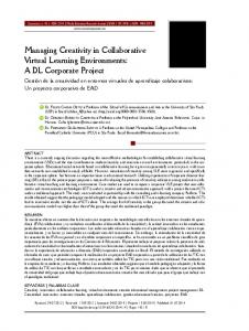
Toy Story (figure 14) is the first film in the history that was completely rendered by computers. It was released in 1995. The rendering of 114'240 frames of the film would take 43 years on a single processor computer of those times. The work distribution to 117 Sun graphics workstations (dual, quad, and and 8-processor) shortened the rendering time to 46 days [Sun 1995][SunWorld 1995]. Many other films followed, such as Bug's Life (1998), Final Fantasy (2001), and Cars (2006, figure 15).
Fig. 14: Computer rendered film Toy Story
Fig. 15: Computer rendered film Cars
17
2 State of the Art Distributed Radiance
Radiance [Ward 1994] is photorealistic rendering system based on ray-tracing techniques. Raytracing is extremely computationally expensive. University of Bristol is investigating possibilities of rendering acceleration by parallel processing on the cluster of computers [Debattista 2007]. Some plans even exist for a project of real-time radiance on a large cluster of computers.
Fig. 16: Scenes rendered by radiance
Computer Workload Distribution: Distributed Simulations DIS
Project DIS – Distributed Interactive Simulation [ANSI 1993] is a large simulation project. Since it enables also interaction of people, it was already mentioned above in this section. Earth Simulator
Earth Simulator [ESC 2007][Wiki 2007] was developed for global warming effect prediction. It was the fastest supercomputer from 2002 to 2004. It consisted from 5'120 processors and 10 terabytes of memory.
Fig. 17: Earth Simulator for global warming effect simulations
18
2.2 Examples of CVE Simulation of Merging of Two Massive Black Holes
The purpose of the simulation of merging of black holes [NASA 2006] was to prove Einstein theory of relativity, particularly one of its consequences – the existence of gravitational waves. These gravitational waves are racing out from two black holes when these black holes are about to merge and they are rotating around each other. The task has two steps: –
to simulate the gravitational waves according to Einstein theory – to get the idea how the waves should look like
–
to measure the real gravitational waves and compare the results with the simulation – this shall prove whether the Einstein theory is correct
The simulation was more computing expensive than all other NASA simulations before. The results are shown in the figure 18. The second step – the real measurement – already started: In November 2005, Laser Interferometer Gravitational-Wave Observatory (LIGO) was finished and started to monitor gravitational waves. The measurements are not easy because LIGO has to be able to detect length contraction of the size of a single atom per one meter. The outcome of the comparing the reality and the simulation is still open.
Fig. 18: The results of gravitational waves simulation and the used cluster of computers
2.3
CVE as Multi-area Research
This section describes the relation between CVE research and the research in other areas. CVE is closely related, for instance, to distributed systems and it has taken many concepts and research outcomes from this area. This section lists the close research areas and their importance for this thesis.
19
2 State of the Art The important related research areas include: •
Parallel and Distributed Simulations: CVE is often distributed simulation application that is running in real time and that is visualizing its results.
•
Distributed systems: CVE is usually realized by several applications running at different computers. From this point of view, it is a distributed application that operates on a shared data.
•
Network communication: Network latency, bandwidth, reliable/unreliable protocol, and multicast support – all of these are in the scope of CVE systems.
•
Real-time systems: CVE systems are often real-time simulations and/or the systems from which the user requires very short response times. In most common applications, the required response ranges from milliseconds to hundreds of milliseconds.
•
Virtual reality: CVE applications maintain the data set that represents the virtual environment. The virtual environments are domain of computer graphics and virtual reality.
•
Database systems: Database algorithms are used in CVE rarely even although both areas are working with the replicated data sets. One of reasons for omitting database algorithms in CVE is the different performance requirements in CVE and databases. The performance reason is overcome in this thesis and some new algorithms and techniques were introduced that are similar to those used in database systems.
In this thesis, the special attention will be given to distributed systems, especially to replication consistency models, and database systems from which some new ideas will be introduced into CVE applications.
Three Layers in CVE Applications Three layers can be recognized in CVE systems, as shown in the figure 19. The layers have different roles, briefly characterized as: network communication, handling of data replication, and smooth visualization for an user.
Dead-reckoning and Interpolation Layer
Message Distribution and Consistency Handling
Network Layer Fig. 19: Three Tiers in CVE applications The middle layer (non-hatched area) is the main interest of the thesis.
20
2.3 CVE as Multi-area Research The layers are related to different aspects of CVE Systems. The main aspects are: Responsiveness
– Capability of the system to respond to the user requests in the specified time frame.
Consistency
– Several consistency models have been designed. They can be studied for consistency guarantees, limitations, and properties in the context of different application requirements.
Scalability
– The ability of the system to continue working as the system's context changes in size or volume.
Persistence
– The ability to stay active even when some/all users have left the session.
Reliability
– The resistance against bad conditions that may appear in the system. Network overloading, lost packets, or some machine failure are often the case.
The figure 20 shows the relations between CVE layers (in blue), close research areas (grey), and the relation to the most important aspects of CVE systems (in yellow). Dead-reckoning and Interpolation Layer (CVE Smoothing)
Virtual Reality and Real-time Systems
Responsiveness
Message Distribution and Consistency Handling (CVE Kernel)
Parallel and Distributed Simulations, Distributed and Database Systems
Consistency, Scalability, Persistence
Network Layer
Computer Networks
Reliability
Fig. 20: Three tiers and their relations to research areas and CVE properties
The focus of this thesis is on the middle layer – handling of the consistency and replication models. The layer will be called CVE kernel in the thesis as it is the cornerstone of whole system and its design determines the main characteristics of each particular CVE system. Other layers are mentioned because they have deep influence on the design of CVE kernel. The network layer partially determines the properties and the guarantees of the network connections in different physical network conditions. The properties of network connections should be reflected by the CVE Kernel layer. For example, unreliable network connections usually does not work properly with active replication. The CVE smoothing layer provides the user smooth results of the simulation. If some updates are delayed, it is able to predict object behavior. Sometimes, the simulation is done in steps. In that case, the natural role of this layer is to interpolate between the simulation steps to give the user the impression of the smooth simulation that is more natural for human perception. 21
2 State of the Art
2.4
Distributed Systems
Scene Replica
Scene Replica
update scheduled
Replicated Scene
Scene Replica
distribution of updates
Scene Replica
Scene Replica
Fig. 21: CVE system with replicated scene
In most cases, a CVE system consists of several remote processes sharing the data set that represents a virtual environment, as shown in the figure 21. The processes are usually distributed among many (possibly distant) computers that are connected through a network. From this point of view, it is a distributed system that usually meets following characteristics: –
virtual environment data are replicated
–
updates propagation is time critical
–
update operations are asynchronous (e.g. Non-blocking)
The replication of the data is important for performance reasons. Each computer participating in CVE simulation typically renders the scene 30-100 times per second. This means that the part of the scene that is rendered must be read from the memory and sent to the rendering device. The amount of the data depends on the application but it can easily overcome even the highest speed network devices for many applications. Therefore, the scene is nearly always replicated. Some protocols for data sharing were developed for distributed shared memory (DSM) systems [Li 1989]. However, CVE systems are usually using data replication, although the protocols are similar or the same. Replication protocols, used in Distributed Systems, may be split into the two categories. Primary-based protocols (also called primary-copy protocols) are centralized approach making one replica primary and all others are secondary replicas, often called backups. Updateeverywhere protocols are non-centralized approaches. They usually perform the updates in parallel on all the replicas. The list of important protocols follows: –
–
Primary-Based Protocols (Passive Replication) –
Remote-Write
–
Local-Write
Update-Everywhere Protocols –
Active Replication
–
Delta-time
–
Quorum-Based 22
2.4 Distributed Systems The replication protocols are described bellow. Replicated scene requires asynchronous updates delivered as quick as possible. Asynchronous updates are required because blocking operations are not acceptable for CVE. They may lower the performance rapidly. On the other side, asynchronous updates result in more complex consistency models compared to the systems using synchronous operations. Quick update distribution is important for good responsiveness of CVE application. They are caused mainly by the network latency (section 2.6) that usually can not be eliminated. Therefore, CVE systems developed several techniques to minimize its effect. They will be shown in the section 2.8. Other important concepts are atomic multicast and distributed timestamp generator. Atomic multicast is an important communication primitive that is often used for the update distribution in CVE and network communication in general. Distributed timestamp generator is another primitive used in distributed systems that is required by many applications. The following subsections are showing the replication models, atomic multicast, and distributed unique timestamp generator in the detail.
Primary-Based Protocols – Remote-Write
Primary Copy 2. 3.
4.
Backup Replica 1.
3.
3.
4.
4.
Backup Replica
Backup Replica
5. Fig. 22: Primary-backup remote write consistency model
The primary-based protocols require one replica to be primary, while all others are secondary replicas, also called backups. The primary is responsible for coordination of all the updates. The update is usually performed on the primary first and then, the primary updates all its backups. Primary-based remote-write protocol [Budhijara 1993] functionality is depicted in the figure 22. One of the replicas is the primary while all the others are backup replicas. If a client wants to update the data item (1.), it has to send an update request to the primary (2.). The primary performs the update locally and asks all the backup replicas to update their values (3.). Backup replicas update themselves and send acknowledge back to the primary (4.). Then, update-initiating replica acknowledges the update completion to the client (5.). Primary-based remote-write protocol is often used in CVE systems. Especially, large simulations are often using it. The disadvantage may be a single point of failure – the primary replica. However, some algorithms exists to overcome the problem even if the computer with the primary replica crashed. Such algorithm may, for example, reconcile the backups values and perform the voting among backups for a new primary.
23
2 State of the Art
Primary-Based Protocols – Local-Write
2.
4. 5.
Backup Replica
4.
4. 5.
5.
Backup Replica
Primary Copy
4.
5.
Backup Replica
3.
1.
Fig. 23: Primary-backup local write consistency model
Primary-based local write protocol (shown in the figure 23) is similar to Remote write protocol except that primary replica migrates. When the write request is issued on a backup replica (1.), the primary migrates to the backup replica (2.). The update is performed locally and the client receives the acknowledgment (3.). Then, all other replicas are contacted to update their values (4.). After the collecting of the acknowledgments (5.), the write operation is completed. One of main problems of primary migration is keeping track of where the primary is located. Broadcasting facilities, forwarding pointers, or home-based approaches can be used. The last two were used in distributed shared memory systems [Li 1989] that are using primary-based replication. Primary-based local write protocol is used in CVE systems in ownership consistency models. Just the computer with the ownership of the data item is allowed to update the value. The disadvantage is the single point of failure as in the previous replication model.
Update-Everywhere Protocols – Active Replication 2.
Atomic Multicast 3.
Replica 1.
3.
3.
Replica
Replica
3.
Replica
4. Fig. 24: Active replication consistency model
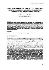
Active replication [Schneider 1990] is a non-centralized approach. Its functionality is depicted in the figure 24. When a client issues write request (1.), it is atomically multicasted to all replicas (2.). Atomic multicast (see bellow) provides reliability even in the presence of failures and guarantees the same receive order of different updates on all replicas. When the update is received by the replica from the atomic multicast, the replica is updated (3.) and the client can be informed about the completion of the write operation (4.). 24
2.4 Distributed Systems Active replication (also called Machine state approach) relies on the determinism: Provided by the same inputs, all the replicas will produce the same outputs. The atomic multicast is used for the distribution of the updates to the replicas. If the determinism is kept, the replicas will stay synchronized. Active replication may seem to be simple, however, its complexity is hidden in the atomic multicast. The requirement of determinism that is required for the update processing is often mentioned as one of the main disadvantages of active replication. Typical examples of nondeterminism sources are multi-thread processing and floating point computations that may not be bit-by-bit equal on different architectures and compilers [Monniaux 2007]. A famous hardware bug exists in first Pentium processors that returns sometimes wrong results when multiplying two numbers [Intel 2004]. Other source of non-determinism are different implementations of the same functionality. For example, many compilers are compiling programs to use MMX and SSE instructions instead of standard x87 code if they are available. However, Intel does not guarantee that the results will be bit-by-bit equal for all instructions for today's processors.
Update-Everywhere Protocols – Delta-Time Memory coherence models usually work with the following criterion: “a read of a data item returns the most recent write to that location”. However, it is not easy to determine the most recent write on a replicated data item in a distributed system. Delta-time consistency model [Singla et al. 1997] takes the network delay into account and uses following criterion: “a read of a data item returns the last value that was produced at least delta time units preceding that read operation”. Assuming that delta is big enough compared to the network latency, each write can propagate to all its replicas in time. The order of writes that may be done by different processes is established and all replicas are able to provide the user with consistent results of the read operation according to Delta-time model. Example timeline of Delta-time model is shown in the figure 25. Three processes are depicted and they are reading and writing to the data item. The read operations are represented by tr and the writes by tw. At first, 0 is written by the process P1. After the delta time, the new value is available at all processes. Then, P1 writes 1. The read on P3 happens before the delta time is reached after the second write, therefore P3 reads 0 because it is already stable value. Finally, P2 reads 1 because the delta time after the second write has already passed.
P1
tw(x)0
tw(x)1 tr(x)1
P2 tr(x)0
P3 ∆
∆
Fig. 25: Delta-time consistency model
The model was extended to Time Sensitive consistency model [Krishnaswamy 2001] that provides timed and non-timed reads and writes. The timed reads and writes provide the user by consistent data view. The non-timed operations are available for the cases when the data freshness is preferred over the data consistency, providing the user by possibility to choose required consistency level. 25
2 State of the Art The figure 26 shows the example timeline. The non-timed reads are shown as r and the writes as w to distinguish them from timed counterparts tr and tw. At first, P2 performs two timed writes followed by non-timed and timed read of process P1. The non-timed read may return 15 because the value may already propagate through the network and the non-timed read is not obliged to obey the delta time. On the other side, the timed read is forced to return 10 in order not to break the consistency requirements because the delta time after the second write did not already passed. However, the non-timed read of the process P3 returns 15 because timed writes force both – timed and non-timed reads to return the new value after the delta time has passed.
r(x)15
P1 P2
tw(x)10
tr(x)10
tw(x)15 r(x)15
P3 ∆
Fig. 26: Time sensitive consistency model
Update-Everywhere Protocols – Quorum-Based The write operation in quorum protocol can be issued on any replica. Then, the replica starts to contact other replicas for performing of the update. If it succeeds at least smallest majority of replicas (half of the replicas plus one), the update is successful. The read operation requires once again to be contacted at least the smallest majority that contains the same value. Then, the value is considered the correct return value of the read operation. Some optimizations and details are in [Tanenbaum and Steen 2002]. Quorum based protocols are nearly not used in CVE application because they require network communication to be done even on read operations and that is not acceptable for the most of CVE systems.
Atomic Multicast Atomic multicast is a communication primitive for delivering messages to the process group with the following properties: –
reliability
–
virtually synchronous
–
total message order
These properties have to be kept even in the presence of process failures. Atomic multicast is based on reliable multicast (see section 2.6) that guarantee the message is delivered to all non-crashed processes in the process group. However, the processes may leave and enter the group and reliable multicast does not answer the question which messages are delivered to the joining or leaving processes. 26
2.4 Distributed Systems Virtually synchronous reliable multicast [Birman 1993] introduces “group views” that keeps track of the members of multicasting group. It establishes a new group view whenever any process enters or leaves the group. The messages sent to the group view Gi have to be delivered before the next view Gi+1 is established. This provides additional guarantees of message delivery. The messages are allowed to be undelivered just in the case of sender failure during the multicasting of the message. If virtually synchronous reliable multicast provides totally-ordered message delivery, it is called atomic multicast [Birman 1993][Whetten et al. 1994]. Totally-ordered delivery means that all the messages are delivered to all processes in the same order. According to [Hadzilacos and Toueg 1994], three types of sender orderings exist: –
Atomic multicast (unordered)
–
FIFO atomic multicast
–
Causal atomic multicast
Unordered atomic multicast does not guarantee that the sending order (viewed by the sender) will be kept. Atomic multicast will deliver them to all the processes in the same order but it may differ from the order in which the messages were seen by the sender at the time of sending. FIFO atomic multicast order preserves the sending order while causal order respects just the order of the causally related messages. For the simplicity of the text, only FIFO atomic multicast will be considered in the thesis and when referencing to atomic multicast, the FIFO atomic multicast is meant.
Distributed Unique Timestamp Generator Distributed unique timestamp generator is based on ideas presented by Lamport [Lamport 1978]. He pointed out that although the time synchronization is possible, it may not be absolute. What really matters is usually the order of the events that all the processes have to agree on. He assigns a time to each event. If some event occurs before other event, it must have lower time, and if it occurs after the event, it must have greater time value. If some events are not related to each other, their order does not matter. The event relations have to be kept throughout the distributed system even in the presence of non-precise clock synchronization. 0
0
0
0
0
0
8
10
6
8
10
12
16
20
12
16
20
18
24
30
18
24
24
32
40
24
32
40
30
40
50
30
40
50
36
48
60
36
48
56
70
42
61
70
64
80
48
69
80
54
72
90
70
77
90
60
80
100
76
85
100
6
A
42 48
D
B
C
A
D
(b)
(a)
Fig. 27: Lamport timestamps (a) Three processes, each with its own clock. The clocks run at different rates. (b) Lamport's algorithm corrects the clocks.
27
B
C
30
60
2 State of the Art The figure 27a shows three different processes and their communication. The process clocks are running at a slightly different rates. The event A is sent at the time 6 and received at the time 16, although it is 12 according to the clock of the first process and 20 according to the third process. However, Lamport does not require to use absolutely synchronized clocks and only the event order matters. The event B is sent at 24 and received at 40 without any problems. The event C is sent at 60 but it should be received at 56. And similar situation happens with the event D. Lamport's solution follows the causality and if event C is sent at 60, it has to be received later. So, the local clocks are adjusted to, for example, 61 to keep the causality in the system. The figure 27b shows the situation after the correction: The event C is sent at 60 and received in 61 and the event D sent at 69 and received in 70. The uniqueness of timestamps throughout the distribute system can be realized by appending the process number or its unique identification as a low-byte end of the time, as Lamport suggests.
2.5
Parallel and Distributed Simulations
CVE applications are often simulating real world, city traffic, weather prediction simulations, etc. and the simulation is visualized on the computer screen. The distribution of the simulation is used either for performance reasons to distribute the workload to more computers, or for interaction purposes – the simulation is synchronized among the computers to give the impression of the shared virtual environment that several users can examine and manipulate. At the beginnings of simulations, the abstraction of sequential discrete event simulator was introduced. It is composed of state variables, event list, and clocks. The events have their timestamps that contain the time when they should be executed. They are taken out of the event list and executed when the clocks reach their timestamp. Through the event execution, other events can be generated that are appended to the event list. There are sequential simulators connected with links in the area of distributed simulations. Those links are used for exchanging of messages. The main problem of distributed simulator is the time synchronization because each event can produce other events for different simulators and simulation of any event should not start until the system is sure it will not receive the event with lower timestamp from other simulators. Chandy-Misra-Bryant (CMB) [Chandy and Misra 1979][Bryant 1977] approach uses link times that indicate the last timestamp of the simulator that sends the message (one-directional links are used and some granularity of time is used). When there are no communication, null-messages are used to update the link time. Any simulator is able to determine the moment when it is safe to get its event with the lowest timestamp out of the event list and to start its simulation. High amount of null-messages is usually considered the main disadvantage of CMB approach. Time Warp [Jefferson 1985] is the most known optimistic protocol that avoids them. It process the events optimistically on all simulators. The causality errors are detected later and the system has to be able to roll back erroneously executed events. Many further optimizations have been developed for both – optimistic and pessimistic approaches. Some of them are related to the thesis and they are mentioned bellow. Many others are omitted, such as simulation cloning [Hybinette and Fujimoto 2001][Chen et al. 2003], concurrent replication [Bononi 2005], and partitioning problem [Morillo et al. 2005] because they are not really relevant for the thesis. 28
2.5 Parallel and Distributed Simulations Temporal Uncertainty
Temporal Uncertainty was proposed by R. Fujimoto at [Fujimoto 1999]. He proposed to relax strict causality of event execution and to use time intervals instead – each event is associated with a time interval and any two events whose intervals overlap at least in one point in common are considered concurrent events that can be executed in parallel. In most simulations, the impact on results is negligible while the performance increases rapidly. Another quite important motivation for temporal uncertainty approaches were, according to Fujimoto, differences between research of distributed simulations and CVE. These differences were quite important because many projects are considered to be both – distributed simulation and CVE system, such as DIS project [ANSI 1993]. But the differences between the both systems make it difficult to connect many of those systems together in federated simulations [Riley et al. 2004]. One of the differences was that CVE usually do not support rollbacks, but temporal uncertainty is able to overcome this limitation. Latency Hiding
According to [Hybinette and Fujimoto 2002], it is possible to locally simulate, for example, an object behavior during the user interaction with the scene and to provide the user with immediate effects on its screen, while it takes some time before the operation really takes the effect. The delay may be caused by the system response time, network latency, or light speed. For example, the communication with robot on the moon will always take about two seconds because of the moon distance. The latency hiding is also important technique for CVE. Real-time Simulations
Many simulations coupled their simulation time with the real time. One of reasons is human-in-theloop simulations, such as training application – the person is trained in the virtual environment (pilots military training, car driving simulations, etc.). Some simulations are used for hardware-inthe-loop testing, like missile tracking sensors and many others. DIS project [ANSI 1993] is one example of real-time simulation including human-in-the-loop, with the possibly of many people participating in the simulation while they are virtually present in the simulated collaborative virtual environment.
2.6
Computer Networks
Computer networks were often mentioned in CVE research papers in the 90's [Waters et al. 1997] because every CVE highly depends on network conditions. Overloaded network switch or lost packets of a wireless connection may cause many difficulties to CVE applications. CVE applications may require as short packet delivery time as possible. Often, reliable and high bandwidth connection is necessary and special abilities such as multicast or broadcast support may be required for scalability reasons. The properties of computer networks are influencing the design of CVE. Particularly, latency, bandwidth, and reliability are usually the most important properties that correspond with responsiveness, scalability, and fail-resistance of CVE systems. 29
2 State of the Art
Reliable and Unreliable Network Connection Two basic protocols are used on today networks based on IP (Internet Protocol): TCP and UDP. UDP is based on datagrams that are transmitted from a sender to a receiver without any guarantees. the datagram may arrive quickly, or be delayed, it may be lost on the way, dropped by some switch, or it may not find a route to the destination. Therefore, this type of connection is often called unreliable. To use UDP usually means for a programmer that he has to face the problem of lost packets and the problem of the order of datagrams that may come in a different order than they were sent. TCP protocol is used for reliable connections. The protocol takes care about resending lost packets and reorders the packets at the destination to the order of sending computer. It is based on UDP, but it is much more convenient for a programmer because of the reliability guarantees. Some discussion can be made what is better for CVE applications. TCP is more convenient than UDP but it has some overhead that may be noticeable for some applications. Particularly, latencylimited applications may require more aggressive time-outs for lost packet resending or lost packet recovery based on additional recovery data. The simple lost packet recovery algorithm was realized in [Lincroft 1999] by duplicating the data of previous packet in the following packet. Even if one of the packets is lost, the data stream can still be reconstructed without the cost associated with the packet resending. To avoid doubling the bandwidth, algorithms based on Hamming code [Hamming 1950] can be used to optimize the network requirements. In conclusion, UDP was often used in the 90's and it enabled better performance. Today, most projects are using TCP because Internet connections and its back-bones improved much in quality and bandwidth. Therefore, UDP does not give so many advantages over TCP as is was before. Moreover, UDP communication is often firewalled on many gateways, making UDP communication not possible.
Multicast and Broadcast CVE applications often send the same message to many computers. As a CVE system grows in size, it became quite performance consuming to send the same message to each one of, for example, hundred computers or even more. Multicast and broadcast are addressing this issue. Broadcast is used from ancient times of computer networks. If a computer sends a broadcast message, it is usually delivered to all computers belonging to that network. This approach was used in DIS [ANSI 1993] and in the first version of DOOM [Roehl 1995a]. Often mentioned broadcast disadvantage is that all computers in the network have to process the message, including the computers that are not interested in it and that it puts extra load on large network infrastructures because the broadcast spreads through the whole network. Multicast is more network friendly approach because a multicasted message is delivered just to computers belonging to the multicast group. This eliminates the main disadvantage of broadcast – network over-flooding that may have deep impact on its performance with increasing amount of broadcast traffic. However, multicast is not supported properly by some switches and routers. In that case, some fallback, such as standard TCP/UDP connection, may be used. Multicast and broadcast are unreliable – there is no guarantees on the message delivery and that all computers really received the message. For this reason, only CVE systems that do not require reliable network connections or that are able to recover lost packets are using multicast and broadcast directly. Otherwise, some reliability layer has to be introduced. Some research was done 30
2.6 Computer Networks on reliable multicast [Chang and Maxemchuk 1984]. Reliable multicast is usually facing a problem of resending packets that is based on negative acknowledgments – correctly received packets are not acknowledged but retransmission is requested for the missing packets. This may lead to feedback implosions when a large group of computers does not receive some packet. The implosions may temporarily overload the sender and the network. Scalable reliable multicast [Floyd et al. 1997] was developed to overcome the problem. It is using feedback suppression. The retransmission request is multicasted and other computers can suppress their request and wait until the message is retransmitted.
Bandwidth CVE applications are used over wide range of network connection types, ranging from slow dial-up connections (typical value today: 56k bps), through DSL connections (typical values: 512kbps to 4Mbps), to highest speed networks (10G bps). It is necessary to design particular CVE application with the respect to the expected type of network and available bandwidth. If the network is overloaded, it may easily result in the application malfunction. Therefore, careful consideration has to be done for safe handling of this issue. The network overloads can be classified into the two categories: •
overloading of some network point, such as router, switch, or local network connection
•
overflow of network buffers managed by operating system
The first category can be avoided by designing the application with the respect to the type of the network connection it will be used on to not exceed the limits of the particular network. However, this can not avoid some extreme situation, such as short peak network loading because of some extraordinary activity of some network users, or overloaded wireless hot-spot on some scientific conference. The second point can be caused by the first one, when the network is not able to deliver the packets quickly enough and the network sending buffers start to fill up. The experience shows that certain level of lost packets results in automatic slowing down of TCP/IP connection. These lost packets are often caused by an overloaded network point. However, the connection accommodates too slowly to higher speed even if there is again enough bandwidth. Another reason for the buffer overflows are some burst send operations, such as sending whole scene to the client when the client is starting and connecting to the server. The scene data often greatly exceeds the default size of sending buffers available for the network connection. If not handled properly, data loss and scene corruption may follow. For example, atomic joins are problem at this point because they require large amount of data to be quickly transmitted (section 3.4). Increased size of the buffers may be an option together with the careful application design avoiding buffer overflows.
Network Latency It can be said that the network latency is a special type of communication latency between two processes. Latencies may vary on different kinds of networks. Typical values for today networks follow: 100us 1-10ms
– quick local networks – hi-speed network connections in one country of a size similar to Czech Republic
31
2 State of the Art ~ 30ms ~ 350ms 100-2000ms
– dial-up connections to a server in the same country (measured in Czech Republic) – connection from Europe to Australia – GPRS Internet connection (between different Internet providers) – may vary
Therefore, a synchronous access to the data of a remote process can be quite time-expensive operation for the local process. Many optimizations have been developed in distributed systems to avoid the cost of the communication. Especially relaxed data consistency and data replication techniques address the issue. CVE system faces the problem of network latency because it is typically updating and rendering the scene even 100 times per second. It means that sometimes 10ms latency may be too long to exchange all the updates between processes. Different CVE approaches are presented in the chapter 3 to face the problem together with some approaches to overcome the problem of the network latency. The network latency measurement is in the appendix – chapter 7.
2.7
Real-time Systems
CVE applications are often real-time systems and it is unacceptable for an user to wait a second for completing of some operation. Such property is important for the most of virtual reality applications that are often rendering the scene fifty or even one hundred times per second. This shows that even the latency of ten milliseconds can be undesirable. In the section 2.6, the network latencies were deeply analyzed. The conclusion may be made that it is not a bad choice to design an application for expected latencies in the range of 10-60ms. For long distance connections, it can be even more. Real-time systems are often constrained by operation deadlines. If the operation is not completed until its deadline, the operation has to be canceled or special handling has to take place. In the worst case, missed deadline could lead to system crashes on some systems. CVE applications has to quickly respond to the user activity and to manage its internal representation of the virtual environment. However, the processing of the virtual environment takes some time because it requires network communications. The latencies of the communication are sometimes unpredictable as shown in the section 2.6. As a result, CVE applications can not use hard deadlines that may crash the application if they are missed. So they should be designed to be safe even under unexpected network conditions, handling temporary connection unavailability, and to give the computer a chance to reconnect after sudden loose of the connection, etc. This tolerance of varying network conditions can be separated into the two areas: –
low-level networking robustness
–
adaptability of CVE Kernel to the current network conditions
The low-level networking was discussed in the chapter 2.6 that was dedicated to computer networks. The adaptability of CVE kernel includes the ability to safely handle delayed updates and temporary unaccessible computers. Another valuable property is adaptability to short/long latencies to provide the best possible performance based on actual network conditions. A special issue is network loading adaptability for the applications that are bandwidth greedy or that are transmitting many 32
2.7 Real-time Systems data in bursts. A performance issue may be the number of simulation steps per second and simulation loading because these may overload some slower computers that may not be able to perform so many simulation steps, resulting in possible instability of the whole system as operation deadlines are no longer met.
2.8
Virtual Reality Systems
CVE systems deal with the data representing a virtual environment. The virtual environment is usually represented by a 3D model composed of triangles. The triangles are efficiently handled by today hardware and other 3D representations, such as NURBS [Piegl and Tiller 1997], implicit surfaces [Bloomenthal 1997], and CSG [Tilove 1984], are usually converted to the triangle representation before they are visualized. OpenGL [OpenGL] is widely accepted standard API for 3D rendering. Another standard is Direct3D [Direct3D] from Microsoft that is also often used, however it is not available on nonMicrosoft platforms. Many applications are using OpenGL directly, sending their 3D data directly to OpenGL for rendering. OpenGL API
Application
Per-Fragment Operations
Per-Vertex Operations
Rasterizer
FrameBuffer Fig. 28: OpenGL pipeline
The figure 28 shows simplified OpenGL rendering pipeline. The data for rendering are sent by the application through OpenGL API. The first stage processing is vertex-based. Roughly said, it transforms all vertices and associated data by the transformation matrixes and passes them to the rasterizer. The rasterizer takes the geometry formed by the vertices (triangles, quads, lines, points) and produces fragments. The processing of fragments includes among other functionalities texturing and depth test. The resulting pixels are written into the framebuffer. The framebuffer is periodically read (depending on the screen refresh frequency) by the graphics hardware and the data are sent to the display. 3D data are usually sent to the OpenGL for rendering. To get the impression of a smooth non-jerky animation, about 20-30 rendered frames per second are often mentioned as minimum. In practice, the refresh rate of the monitor is often used. The monitor refresh rates ranges from 60 (on LCDs) to 90 (CRT) and sometimes even more. Some applications are using high-level libraries for representing virtual scenes, such as Open Inventor [Inventor], OpenSceneGraph [OSG], OpenGL Performer [Performer], and many others. They provide encapsulation of many graphics algorithms and routines thus shortening the
33
2 State of the Art development time of the application. Many CVE systems put their collaborative algorithms inside these libraries, changing their virtual scenes to collaborative scenes. Some examples are DIV [Hesina et al. 1999], [Peciva 2005], Avango [Tramberend 2001], and Blue-c [Naef et al. 2003]. The user of such libraries is usually able to profit from the collaboration using simple API that encapsulates possibly really complex CVE algorithms. Immersive virtual reality
Immersive virtual reality became a term for virtual reality that is so similar to the reality for the user perception that he is nearly able to forget he is in the virtual world. The level of the immersion can be different depending on used hardware. Some special hardware for increased immersion follows: –
Head-Mounted Display [Forte]– typically two display screens, one for each eye, and motion tracker; The displays provide the user by 3D scene view while motion tracker continuously measures head position and orientation to update the scene view. The first widemarket attacking HMD was VFX1 from Forte. It is shown in the figure 29.
–
Stereoscopic viewing – perception of depth and the sense of space
–
Gloves – sense of touch; The user is able to feel the objects through gloves, manipulate them, and interact with them.
–
Haptic – sense of touch; The user is able to touch and manipulate objects through a haptic device [Haptic]. A haptic device is shown in the figure 30.
–
Sound – provides the user by audio perception
–
VirtuSphere [Technovelgy] – free walking; sphere rotates freely as the user is moving (figure 31)
Fig. 29: Head-Mounted Display (HMD)
Fig. 30: Haptic device
Augmented virtual reality
Augmented virtual reality usually uses a 3D glasses with a small camera inside. The camera signal is going into the computer, it may be processed, and it is mixed with virtual scene objects. The picture 32 is showing two users interacting with virtual objects in augmented reality on Vienna university [Kaufmann 1999].
Fig. 31: VirtuSphere
34
2.8 Virtual Reality Systems
Fig. 32: Augmented Virtual Reality
Collaborative techniques Several techniques are used in virtual reality applications when collaboration of virtual environments is used. The techniques are aimed especially to lower the network bandwidth and to provide smooth and non-jerky animation to the user. Dead Reckoning
Dead reckoning was used long time ago for the ship navigation. With stellar observation, the navigation is “live”, working with the stars and the movement of the planet. With logs, compasses, clocks, but no sky, the ship navigator is working “dead”. “Dead reckoning is the process of estimating one's current position based upon a previously determined position, or fix, and advancing that position based upon measured velocity, time, heading, as well as the effect of currents or wind.” (Wikipedia, 2007) In CVE systems, it is usually not possible to distribute scene updates on per-rendered-frame basis because 60-100 frames is often rendered per second. That would lead to high network traffic, or even to reach network limits. It is also possible to eliminate the effect of the network latency by estimating the object position from the last known data. The term “dead reckoning” [Roehl 1995a][Cai et al. 1999] was introduced to CVE in the project SIMNET [Calvin et al. 1993] in the 80's. SIMNET was predecessor of DIS project [ANSI 1993]. DIS used dead reckoning for objects behavior, such as tank, airplane, and missile movements. Because the simulation was including thousands of them, it was necessary to lower the number of updates. Since these objects often follow straight paths or easily predictable paths. So, dead reckoning can be used to predict the object position for the close future based on, for example, current position and velocity vector. DIS is computing the difference between the predicted position of the unit and its real position. When the difference reaches some threshold, the next update is sent to all replicas. The replicas will receive the update that consists of object's position, the time of the position, and object's velocity vector. Then, dead reckoning on the replicas updates the unit state and smoothly interpolate the unit position to the new trajectory. This way, huge network traffic reduction can be reached. 35
2 State of the Art
Fig. 33: Fighter using dead-reckoning
The similar technique is prediction [Hor and Yonekura 1999] that may be used, for example, for reduction of the network latency impact on the user. Key-frame Interpolation
Key-frame interpolation is sometimes used, for example, in computer game simulated environment. The simulation is running in steps, for example, 10 steps per second. Each step produces a number of updates that are synchronized among the computers. The slowest computers may render just 10 frames each second and the highest performance computers may render 100 frames per second while they interpolate the object positions between the last two simulation steps. The approach was used in the computer game Age of Empires and the algorithm is described in [Bettner and Terrano 2001]. S
R S
R
R
R R
R
S
R
R
R
S
R R
R
S
R S
(S – simulation step, R – rendering step) Fig. 34: Key-frame interpolation
The figure 34 demonstrates the collaborative simulation. The first line shows processing of the high performance computer. The computer is performing five rendering steps between any two simulation steps. The position and behavior of object is interpolated through the time between the key positions given by the simulation steps. The high performance computer is three time more powerful than the second computer shown on the second line. The computer is capable to perform just the simulation step and render it only one time. However, both simulations are running synchronously because the same number of the simulation steps is done. Active replication (see section 2.4) is often used in such environments. Area of Interest
Area of Interest [Benford et al. 1993] eliminates number of updates and associated network and processing resources. The unnecessary updates are detected by awareness algorithms [Benford et al. 1994]. The simplest awareness models are often based on spatial distance – the distant objects do not need to be synchronized because they are far away from the users view and they do not have any direct consequences on the part of the virtual environment that is close to the user. The example of car and city traffic simulator can be given: The cars positions from an other quarter of the city do not need to be synchronized as the cars are not rendered until they get close to the users car. Thus, they do not have to consume network and computing resources. 36
2.8 Virtual Reality Systems The same algorithm was also used in DIS [ANSI 1993] project. Earth was spatially divided to the areas and each unit send updates just to the areas that were spatially close enough to the unit.
2.9
Database Systems
Distributed databases are related to CVE systems because both of them are working with the data that are distributed and replicated. Virtual scene data are often called scene database. The question can be asked, how much do they have in common. The scene data can be converted into database data and stored in database tables, so the scene data can be theoretically treated as database data. The performance requirements can be fulfilled by real-time databases that are focused more on performance than traditional requirements of safety and durability of the data. A typical difference is in the kind of access – CVE systems are accessing the data directly, winning the performance, while databases are usually using SQL [SQL-92] as intermediate language to communicate with the database. If it is possible to store 3D scene into the database, it is also possible to think about replication models in databases and distributed database models and to consider their application in collaborative virtual environments. Databases and transactions
Database may be considered as (possibly remote) data stores. The access to them is usually realized by transactions. The transaction is ordered list of operations that can be executed by the database while fulfilling ACID properties [Gray and Reuter 1992]: –
atomicity – all effects made by the execution of the transaction are either applied all to the database or the transaction has no effect (the case of abort or failure)
–
consistency – if the database is consistent before the transaction execution, it is also consistent after the execution
–
isolation – even if transactions are executed concurrently, the system guarantees that for every pair of transactions Ti and Tj, it appears that Ti either finished execution before Tj started, or Ti started execution after Tj finished
–
durability – after the transaction is finished, the changes it has made persistent even if there are system failures
The process of the transaction execution is depicted in the figure 35. Client Transaction issued
Database Scheduler
Execution
Fig. 35: Transaction processing
37
Datastore
2 State of the Art The transaction is issued by a client and it is usually specified in SQL language [SQL-92]. Then, the transaction is received by the database. The scheduler contains the list of all pending transactions. It may reorder them to get the best database performance because the transactions can be executed concurrently and good scheduling order may avoid many concurrency violations followed by many execution restarts, thus increasing the performance. The transaction execution results in reads and writes that are performed on the datastore. If the transactions are executed concurrently, some concurrency control protocol has to be used when reading and writing to the datastore. Otherwise, concurrency violations may result in data inconsistencies if not handled properly. The transaction execution is finished by the commit or abort. The commit results in permanent record of the changes in the database and the abort removes all the effects of the transaction that may be already made. Consistency Models – Locking Protocols
Locking protocols avoid consistency violations by locking the data that the transaction is accessing. If the transaction wants to read or write some database record, it has to get the read or write lock for the record. All the locks are released at the transaction commit or abort. If the transaction wants to access the database record that is already locked by another transaction, it tries to get the lock. If the lock is compatible with the first lock, it can safely proceed. Usually, shared locks and exclusive locks are used as shown in the lock compatibility table (see table 1). The shared locks (S) allows only reading of the data item, but several transactions can get shared lock. The exclusive lock (X) allows both – the read and write access to the data item, while only one transaction can own exclusive lock at any time. If the current lock is not compatible with the requested one, the lock is not granted. A straightforward solution is to abort and restart the transaction that failed to get all required locks. The waiting for lock to be released may be other option, however it may lead to dead-locks. S
X
S
true
false
X
false
false
Table 1: Lock compatibility table
Consistency Models – Timestamp Ordering Protocols
Timestamp ordering protocol [Reed 1983] assigns each transaction its own unique timestamp. Each data record has associated two timestamps. One of them is holding the timestamp of the transaction of the last read operation, and the other the timestamp of the last write. Six rules are described in [Silberschatz et al. 2002] that are used for concurrency violations detection. Roughly speaking, it works like this: If the transaction is trying to read the record and the record has higher write timestamp than the transaction, the value has been already overwritten and the transaction has to be aborted. The write timestamp has to be lower than transaction's timestamp for the read operation to proceed. The write operation obeys similar rules: If the transaction is trying to write the record and the read timestamp is higher than transaction's timestamp, the transaction has to be aborted because another transaction already used the record's value. If the read timestamp is lower, write timestamp is tested also to be lower, otherwise the transaction is trying to write obsolete value and it has to be aborted. Several optimizations were developed, lowering the number of consistency violations and number of transaction aborts. The most important for this thesis are multiversion databases [Reed 1978] that 38
2.9 Database Systems are used, for example, by Oracle [Silberschatz et al. 2002]. Multiversion databases keep several versions of data records. Therefore, if the transaction is trying to read and the record has higher timestamp, it is not necessary to abort the transaction, but the appropriate value from the multiversion database is returned. Distributed and Replicated Databases
Distributed and replicated databases involve cooperation of several computers on whose the database is distributed or replicated. Distributed databases splits the data of the database so that different parts of the database reside on different computers. A frequent reason for distributed databases is storing of large databases that overcome the limits of a single computer because either performance limits or hardware limits. Another possible reason is localization and data migration depending on the access requirements. So, the data can be available at the server that is the most closest one to the client that most often uses the data. Replicated databases are used in order to increase data availability. The data can be replicated among the number of database servers, increasing the overall database performance because any of the servers is able to respond to the data access requests. However at most cases, any write requires advanced coordination to update the data on all the servers. The updating all the replicas is usually handled by the replication protocol. Replication protocols were described in the section 2.4 Both the replicated and distributed databases are requiring the coordination on their transaction execution to prevent data inconsistencies in the cases of failures. Two phase commit protocol [Lampson and Sturgis 1979] is often used. Three phase commit protocol [Skeen 1981] is used to avoid possibly long database restorations after the failures. Real-time Databases
Real-time databases are usually keeping the database in main memory for performance reasons. The main memory is more expensive than disk space, but disk performance and its data access latency – about 10 ms, limits the performance of the database and execution of hundreds or thousands of transactions per second is usually not possible. Main memory databases [Garcia-Molina and Salem 1992] are able to provide such performance, but data durability is a problem in the case of system crash. One option is to store system log in stable storage. In such case, the log re-execution makes the database restoration possible after the system crash. However, even if disk I/O bottleneck was removed for main memory databases, other bottlenecks may be reached. Creation of system log can be one candidate, depending on stable storage throughput. Another possible bottleneck is in locking operations and transaction execution planning. It can be optimized for main memory databases. Real-time databases are real-time systems. Real-time systems are such systems that works with deadlines [Silberschatz et al. 2002]. The deadlines are characterized as follows: –
Hard deadline. Missing the deadline can cause serious problems, such as system crash.
–
Firm deadline. The task completed after the deadline has zero value.
–
Soft deadline. The task has diminishing value if finished after the deadline.
The transaction management and transaction execution planning should take deadlines into account and they may even abort other transactions holding the lock required for the execution of the transaction with close deadline. The transaction processing in real-time databases are discussed in [Abbott and Garcia-Molina 1992] and [Dayal et al. 1990]. A problem with real-time databases is that it is difficult to predict time cost of transaction 39
2 State of the Art execution. It is often important to ensure that excess of processing power is available. Otherwise, the system may not be capable to handle all the transactions with deadlines in time.
40
3 Analysis
3
Analysis
This chapter describes the consistency models used in Collaborative Virtual Environments (CVE) and investigates their properties. The properties are summarized and weaknesses and strength of different approaches are shown. Finally, the suggestions are given for a new and robust CVE approach. The new approach, that takes the suggestions in the account, is presented in the chapter 4. CVE is long-term trend in visualizations and interaction. One reason is success of Virtual Environments (VE) because the human perception can easily perceive them and to treat them in a similar way as the reality. Moreover, some situation can be visualized or simulated in virtual environment, while they may be much more expensive in reality. For example, a virtual car simulator that is able to show all difficult traffic situations in few minutes while several hours drive is necessary in reality and it includes the risk of an accident. Completely synthetic virtual environments are useful in many cases but people often want to use them for interaction with others (pilot training) or to collaboratively share the data (collaborative CAD software). Social context of collaboration can be seen in some computer games that require cooperation of group of people for reaching some goal. These are often more popular than singleuser games for the inclusion of social feeling. Since the collaboration abilities importance is growing and human social context can be clearly seen, CVE is an important trend in computer graphics for the future. The collaboration is not trivial to realize. It often requires replication of the data among all participating computers (see section 2.4) and keeping the data consistent. Several data consistency models already exist for this purpose. They provide different consistency strength and different system performance characteristics. However, the trade off exists between the consistency strength and the performance unless some sophisticated methods are used. It is often difficult to design the system with strong synchronization because of performance reasons. Weaker models are, in general, making application design more complex and they are more difficult to design and to be understand by the programmer. Although this thesis primarily focuses on strong consistency, it addresses both issues – the performance and usability, and tries to meet the requirements of both. The model with stronger consistency provides additional consistency guarantees over the basic guarantees of the weak models. The additional guarantees are often superior to the basic ones, so they will be called high consistency guaranties throughout the thesis. The term consistency guaranties is used just with the relation to the strength of the consistency; therefore, it is not defined in the presented work. The chapter has three main parts: At first, the short introduction is made on consistency problems in the section 3.1. Then, the classification of different consistency models' designs is introduced (section 3.2) and the typical CVE consistency models are presented and classified according the given classification (section 3.3). The classification of consistency models is important for the design of a new approach and it is aimed to the requirement of performance. Another classification is introduced in the section 3.4, based on consistency model properties and convenient usability. The models are classified and the final section 3.5 summarizes the state and gives the requirements and possible ways for the new approaches. Since no suitable classifications exist in bibliography available to me, I proposed both classifications by myself and used them. The typical CVE configurations were chosen also by me while the main distinguishing factor is data replication model. I described the models and their 41
3 Analysis behavior. The main contribution of the chapter is the classification of consistency models and their properties that can be used as a foundation for a new consistency model. The whole chapter does not provide exhaustive description of consistency models in CVE. It just characterizes those ones that are considered the most important for this thesis. The text does not consider all nuances of already existing consistency models and some aspects that are not important for this thesis may not be covered.
3.1
Consistency Issues
Consistency models are designed to keep application data consistent. Replication protocols [Wiesmann et al. 2000] are already handling basic consistency problems, such as concurrent writes of different computers on the same data item. However, the level of the consistency given by the replication protocols is not high enough for many applications. They may require additional guarantees because some relations may exist among data items that have to be kept by the consistency protocol. This section demonstrates several typical consistency problems that the replication protocols are not intend to handle and they may be required by the application.
Texture node dimensions
Computer A 1. Update texture dimensions 2. Texture data update
data
3. Data update is delayed
Computer B Texture node
4. Replicated dimension update
dimensions data
5. Access to non-consistent texture node
Fig. 36: Partial object update consistency problem
The figure 36 shows a consistency problem caused by partial object update. Two updates that should be applied atomically are applied in different moments and an access to the object is done between the updates. The access will read the object in non-consistent state that may lead to application failure. The problem is studied in this thesis as scene access level property of consistency model and as an ability to group the read and write operations accessing the scene.
42
3.1 Consistency Issues Computer A Texture node dimensions
1. Update texture dimensions 2. Texture data update
data
3. Dimensions update is delayed
Computer B Texture node dimensions data
4. Replicated data update (without updating dimension first!!!)
Fig. 37: Out-of-order update consistency problem
Many CVE systems are not forcing the updates to be executed in the order of their sending. This helps to gain some performance but it is source of consistency problems. One example is shown in the figure 37. The example contains texture node with two attributes: dimension and data. The dependency exists between the dimension attribute and amount of memory allocated for the data attribute. If the user sets the dimension first and then he updates the data, there is no problem on Computer A. But if the dimension update is delayed and Computer B receives the data update first, serious problem occurs. The processing of texture data update without processing the dimension update first may cause writing behind the allocated memory block because the dimension update is meant to reallocate the memory according to the texture size. Thus, the message delivery order may have serious consequences for the application stability. The problem is studied as message ordering property in consistency models. Computer A
1. Node created
5. Delayed update: node replica created
Computer B
Computer C 2. Node replica created
4. Update message for non-existing replica
3. Node updated
Fig. 38: Causality consistency problem
43
3 Analysis The figure 38 shows causality consistency problem. The node is created by the Computer A. Then, the computer B receives the scene update of node creation and creates its own node replica. Immediately, it decides to updates its value. The update message is sent to Computer A and Computer C. However, it may happen, because of strange network conditions, that Computer C has not already received the message about the creation of the node from Computer A, thus it has not created its replica yet. But it may already receive the update from Computer B for a node that does not exists at Computer C. If the situation is not properly handled, serious application stability problems may occur, such as writing to unallocated memory.
3.2
Design Concepts of CVE Systems
I have investigated many projects to find different design concepts used in CVE. Based on the investigation, I chose several criteria that will be used for the classification in this thesis. The classification is focused on design concepts and performance: Criterion
Used Options
Architecture
client-server (1-server, N-clients) distributed-server (M-servers, N-clients) peer-to-peer
Replication protocol
primary-based (local-write, remote-write, ownership protocols) write-everywhere (active replication)
Message ordering
no-order FIFO causal-order total-order
Message delivery guarantees
reliable unreliable
Scene replication type
full partial
Validation
strong strong with the limited access weak
Access level
single operation hard-coded atomic action programmable atomic action user-defined message model Table 2: Consistency models classification criteria
The architecture describes the system configuration and the role of computers. A popular architecture is client-server for its simplicity. One computer is the server and all the others are clients. When using primary-based replication protocols, the server holds the primary scene and the clients are backup replicas. Such configuration is simple to design and good solution for small scenes. 44
3.2 Design Concepts of CVE Systems Distributed server architectures increases the performance limits by distributing the primary scene among more computers, ranging from a small server cluster to large computing servers counting thousands of computers. Peer-to-peer architecture is often used with active replication (see section 2.4). It is non-centralized approach and its advantages include strong consistency and better fail resistance. The replication protocol describes the type of the replication in the system. The most often used protocols in CVE are primary-based (see section 2.4). The primary-based replication requires one replica to be the primary and all the others are backups. All the updates have to be performed by accessing the primary, that, as a consequence of its update, updates all the backups. The opposite approach is active replication (see section 2.4). All the replicas are peers and any update is sent to the all replicas by atomic multicast (see section 2.4). The atomic multicast guarantees that all replicas receives the updates in the same order. If the determinism requirements are met, the processing of the updates in the same order results in the same replicas state on all computers, thus, computers are kept completely synchronized. Message ordering (or updates ordering) influences deeply the consistency guarantees. Three basic types of message ordering can be distinguished: –
per-computer orderings (no-order, FIFO order, causal order)
–
per-item orderings
–
system-wide orderings (causal order, total order)
The per-computer orderings provides per-computer-pair ordering – between source and destination computer – guaranteeing that all messages sent from the source computer will be delivered to the destination computer in the correct order. Often used orderings are no-order, FIFO order, and causal order. No-ordering means that the messages sent in certain order are received in unspecified order. The message re-ordering is caused, for example, by the non-constant network delay and packets routing. Some applications do not accept to work with unordered messages. Others may benefit from it ([Roehl 1995a]). For example, the application may not be interested in previous update if newer update already arrived that replaces the effect of the previous one. Waiting for the previous update would just lower the application performance. Unordered messages are used more often in weaker consistency models and with unreliable communication. FIFO ordering guarantees the receiving order of messages to be the same as their sending order. FIFO order is widely used ordering and it can be easily realized by TCP protocol that is the most used Internet communication protocol today. Causal ordering is weakening of FIFO requirement. The correct order is required just for the causally related messages. This may result in higher performance compared to FIFO ordering. The per-item orderings (compared to per-computer orderings) provides the ordering on different granularity level – on per data item level. Usually, this ordering is not often used because the percomputer ordering is created anyway as a consequence of single-threaded execution of the application or by serialization on a single network card. However, special architectures, multiprocessor servers, and multi-network-card configurations may benefit from this. But such special cases with per-item orderings are rare and they are even more weakening the consistency guarantees. This thesis is focused especially on models with strong guarantees. Therefore, they are not studied here. 45
3 Analysis System-wide orderings shift the consistency guarantees to the higher level. Total order requires all messages in the system to be seen in the same order by all computers. Causal order, when applied in system-wide context, forces just causally related messages to be seen in certain order on all computers. System-wide orderings provides more consistency guarantees, possibly simplifying the application design while trading of scalability. The most often used message orderings are total order and FIFO order. One of the reasons to not using weaker orderings can be high qualities of today networks, compared to early and middle 90's. Now, it seems that the benefits gained by weaker orders are not so important for the most of mainstream applications. Message delivery guarantees provided by computer networks are usually of two types: reliable and unreliable (see section 2.6). Unreliable communication does not take care about lost packets and message receive order. Some messages may be lost and others may be received in a different order than they were sent. Reliable communication handles these things automatically. I have found three types of the most often used connection types: –
UDP communication and unreliable multicast
–
TCP communication
–
reliable multicast protocol [Chang and Maxemchuk 1984], [Floyd et al. 1997]
UDP is sometimes used when no high consistency requirements exist and high performance is required. TCP is probably the most often used communication for its usage convenience. Reliable multicast is the subject of research of some papers because the original multicast concept does not provide reliability. Scene replication type is full or partial. The full replication is nearly always required by active replication. The requirement of full scene replication is in the contrast of the optimizations based on Area-of-Interest techniques (section 2.8) that do not replicate the parts of the scene that are not in the interest of the client because they are, for example, too far away from the user view. Validation is used for concurrency control because many computers may access the scene at the same time and some operations may be not compatible with operations of other computers. The validation may not stay only at lowest level of accessing variables, but it may include some high level behavior, such as scene constraints, user-defined code, and collision detection that avoids penetrating solid objects to each other by refusing the updates that broke penetration condition. client
server
clients
execution update request created
validation
update
update
Fig. 39: Update processing with validation
A typical update processing with validation is depicted in the figure 39. Some client creates the update request and sends it to the server. The server performs the validation and if everything is right, it applies the update to its scene and all clients are asked to update their replicas. If the validation is not successful, the update request is refused and the scene is left unchanged. Some advanced applications may try to reconcile the request with the current scene content and avoid the update refuse. 46
3.2 Design Concepts of CVE Systems The need to validate the update request is the result of concurrent scene access that is performed through the network, thus it suffers from the network latency. The problem of concurrent access is shown in the figures 40a-d. The figure 40a shows Client A that accesses the server to perform a scene update. The server accepts the update and acknowledges it to Client A. It can be seen that the scene state on the server is transformed directly from the state 1 to the state 2. The same happens on Client B, but it is delayed by the network latency that may vary in time and among the computers. The state transfer on Client A that issued the update request is, however, different. The scene is transferred from the state 1 to state 2a. The state 2a is considered temporary and it means that some update happened locally but it is not acknowledged by the server yet. After the acknowledgment, the state is transferred to the state 2. In the case of the update refuse by the server, the scene state turns back to state 1. The same situation is shown in the figure 40b when the update happened on Client B. The same schedule of events applies. Client A
Server
Server
Client A
Client B
State 1
State 1 State 1
State 1
update
update accepted update accepted
State 2 State 3
State 2
State 3
b) Client b updates the scene
a) Client A updates the scene Server
State 1
Client B
Client A
State 1
State 1
State 1 update
update accepted update rejected
State 2 State 2
Server
Client B
State 1 State 1
update
State 2a
State 3a
State 3
State 2
Client A
update
State 1
State 1 State 2a
Client B
update
update
State 2a
State 3a
State 2 3a rollback
update accepted
State 2
update accepted
State 3
State 2
State 3
c) Concurrent updates of client A and B, the updates are non-compatible
State 3a State 2 State 3
d) Concurrent updates of client A and B, the updates are compatible
Fig. 40: Update concurrency
The different situation occurs if the update requests on Client A and Client B occur simultaneously. The situation is depicted in the figure 40c. The update is requested on both clients at about the same time. Both of them are sent to the server. The server receives them in certain order. One of them, usually the first one, is executed first. It is validated and applied. Then, the second one is validated and if the updates are not compatible, the update is refused. In the figure 40c, the update of Client A 47
3 Analysis is accepted and update of Client B is refused. The negative acknowledgment is sent to Client B and it rolls back all the changes related to the update. The state changes on Client A are the same as in the figure 40a. The server state is the same too because the update request from Client B was refused. However, the client B state changes differs from the figure 40b. The state 3a is present after the update request is sent. Then, the update from Client A is received that may not be compatible with the state 3a, therefore it may replace the effect of the unacknowledged update request and the scene enters the state 2. Then, Client B receives the negative acknowledgment of its update and it rolls back all the remaining effects of the state 3a. Another situation occurs if both update requests happened concurrently, but they do not interfere with each other and both of them are accepted. The situation is shown in the figure 40d. The server accepts the first update and sends update to the clients. Then it accepts the second update and sends next update to the clients. All clients are progressing in the state from 1 to 3. The differences are just in the temporary states (state 2a and 3a) and in the time of applying of the update. The validation will be called strong in this thesis, if it uses up-to-date data only – that is the primary data in the case of primary-based replication. If the client-server architecture is used, the server holds the primary scene and it is able to perform strong validation while clients can do only weak validation unless they are sure they have up-to-date data. On distributed primaries architectures, the primary scene does not reside on one computer, but it is distributed. This fact makes the strong validation more difficult to realize because much of the data available locally are just backups. The validation has to either not access backup data or to make remote access to their primaries. If none of the two is an option, the validation may be relaxed to use weak validation. Weak validation allows the usage of the backup data that may not be up-to-date. It may result in scene inconsistencies and the application has to be designed robustly enough to be able to live with them and reconcile or converge them quickly enough. On the other side, weak validation usually increases the scalability and performance of the application. Some applications with distributed primaries may use a special kind of strong validation that does not require any access to the backups. Such validation uses only the primaries that are available locally and it will be called validation with limited scene access because the validation process is limited just to the part of the scene that is composed of primaries. On the other side, the validation process, that is allowed to access whole scene state, either because a weak validation is used or the whole scene is up-to-date, will be called non-limited. Access level can be one of the following: –
single operation
–
hard-coded atomic action (often called event)
–
programmable atomic action (generalized event)
Single operation is, for example, one read or one write operation performed on the scene. These operations are issued by computers and they are accepted or refused by the validation process. The reasons for refusing are usually some consistency restrictions, collision detection, scene defined constraints, etc. However, single operation does not provide abilities for atomic access to a group of data items. For example, it is difficult to handle situations when partial update of several data items of an object would lead to the object inconsistency. In such cases, some higher access level may be a better option. Hard-coded atomic action is a sequence of operations that are executed atomically. It is similar to stored procedures [Silberschatz et al. 2002] used in database systems. If the action is well designed, 48
3.2 Design Concepts of CVE Systems it provides atomicity and gives the programmer advanced access to the data items. Many systems, such as DIVE [Frecon and Stenius 1998], are using term “event” for what is called hard-coded atomic action in this thesis. The idea of programmable atomic actions is quite similar to the transaction concept [Gray and Reuter 1992] used in database systems. Programmable atomic actions extend hard-coded atomic action concept by possibility to specify the action in run-time while hard-coded actions have to be known in compile-time. Programmable actions give the programmer extensible access to the scene that is not limited to the set of hard-coded actions. A typical example that can not live with limited set of actions is a CVE library encapsulating CVE algorithms. The library can not know all the varieties of actions that different kinds of applications may need. Or, there may be a requirement of scene extensibility by new object types and actions that are not known at the application compile time. Programmed actions can be specified at run-time. Users can define what the action shall read and what it shall write. The next step forward would be not using static read and write set. Instead, the transaction would be specified by a script that may create read and write set dynamically. The advantage of using scripts should be that they may take current scene state into the account while the current scene state is not known in the time of the transaction creation. This may avoid many transaction aborts and increase the application performance. However, the scripting is going far beyond the scope of this thesis.
3.3
Typical CVE Configurations
I identified several the most used configurations used in CVE systems: –
Centralized Primaries model
–
Distributed Primaries model
–
Data Ownership
–
Active Replication
The configurations can be classified according to the criteria given in the section 3.2. The classification based on architecture and replication model is shown in the figure 41 and the complete classification of all criteria is in the table 3. The details related to each of the four configurations will be explained in the following subsections. The subsections do not define the configurations formally because it would be difficult to make the definitions abstract enough to cover all possible nuances and specialties of different CVE systems. Centralized Server
Centralized Primaries
Distributed Server
Distributed Primaries
Data Ownership Primary-based Replication
Fig. 41: Architecture classification of consistency models
49
Peer-to-Peer
Active Replication Active Replication
Table 3: Classification of consistency models focused on design
3 Analysis
50
3.3 Typical CVE Configurations
Centralized Primaries Centralized primaries consistency model is based on primary-backup replication model. Depending on the implementation, either primary-backup local write protocol or remote write protocol (section 2.4) from distributed systems can be used. At this model, all primaries reside on one computer called server and they are forming primary scene. All other computers are called clients and they hold just scene backup replicas. All backup replicas in the system are readable and write access is allowed only into the primary replicas. Whenever a client wants to update some data, it has to send an update request to the server. The server may perform some scene consistency checking and accept or refuse the update. If the update is accepted, the primary replica is updated and the message is sent to all backup replicas to update their values.
Replicated Scene
Scene Replica
Scene Replica
distribution of updates
Primary Scene
Scene Replica
Scene Replica
update request
Fig. 42: Centralized primaries consistency model
The figure 42 shows five computers. The computer at the bottom is the server containing the primary scene. All other computers are clients. The computer at bottom-right wants to update the scene. It sends the update request to the server. The server processes the request and if it accepts the request, it sends the update to all clients.
client
server
clients
execution update request created
strong validation
update
Fig. 43: Validation in centralized primaries model
51
update
3 Analysis The update processing is shown in the figure 43 in more detail. The processing has four stages: 1. creation of update request at a client 2. update validation on the server 3. performing of the update at the server 4. update on all clients Client A
Request latency
Server
Client B
Re qu est Up da te
te da p U
Update latency
Fig. 44: Client update latency in primary-based models
The figure 44 depicts the time line of the scene update processing. Two types of latencies can be seen. They are called request latency and update latency here. The request latency is the latency on Client A between sending the request and actual updating of its scene after the server confirmed the update. Update latency reflects the time between the server process the update and the time when the particular client receives the update. The system using centralized primaries model has to be designed to live with these latencies. The request latency is important for the responsiveness of the application. It can be masked by providing the user by some visual or audio feedback (see section 2.8), or the updates can be applied temporarily and validated/reconciled after the server response. The update latency is related to the scene consistency and to the concurrent access of clients to the server scene because the access suffers from inherent network latency. Since the updates are not immediately seen on clients the backup scenes can be temporarily out of synchronization until the updates arrive. This may lead to sending update requests by clients that are not based on up-to-date scene data and therefore they may not be valid sometimes. The server has to be able to refuse invalid updates or to reconcile them with the current scene state. More details concerning validation were described in the section 3.2. From the point of this thesis, centralized primaries consistency model is interesting for centralizing whole primary scene at one place. Such property enables the kinds of scene processing that requires the access to the whole up-to-date scene or to large part of it. A typical algorithm that requires such access is collision detection that has to process all the scene objects for collisions. Since it is the primary scene, no delayed updates exist, and collision is performed on up-to-date data resulting in always correct results. Another interesting thing of the primary scene centralization is validation (see section 3.2) that can be used, resulting in strong consistency and better usability of the consistency model. The disadvantage of the client server architecture is its scalability because the server may quickly become a bottleneck if the system loading is too high. From the point of safety, the server is single 52
3.3 Typical CVE Configurations point of failure of the system. It is safe against client crashes, but the server crash usually results in the failure of the whole system. Advantages: –
strong validation
–
simple design
Disadvantages: –
limited scalability
–
single point of failure
Although centralized primaries model has its advantages, it does not often appear in the research papers. Many projects are using other primary-based models. One reason is data access latency as different data may be required to be placed on different computers for minimizing cost of accessing them.
Distributed Primaries Distributed primaries consistency model is similar to centralized primaries model except that the primary scene is distributed among the computers. The parts of the scene are “owned” by different computers and each computer is allowed to write only to its part of the scene. If a computer wants to write to the part that belongs to another computer, it has to send a request to that computer to update the scene. Clearly, this approach is based on primary-based local write or remote write protocol (section 2.4) from distributed systems.
Pri./Repl. Scene
Pri./Repl. Scene
Replicated Scene
distribution of updates
Pri./Repl. Scene
Pri./Repl. Scene
update Pri./Repl. request Scene
Fig. 45: Distributed primaries consistency model
The processing of the updates and update requests is depicted in the figure 45. It is quite similar to centralized primaries model. The difference is that the update request has to be sent to the correct 53
3 Analysis computer that holds the primary of that particular data item or data items. The primary parts of the scene are marked red in the figure, and backup parts are in blue. After the processing of the update request, the computer that holds the primary is responsible for updating the backups on other computers. The timing and latencies of the update/update request is the same as with centralized primaries. However, the problems of concurrent access and scene consistency are even more difficult because there is no central point of validation like the server in centralized primaries that was validating all the update requests. Each computer has to perform the validation for all it's primaries by its own because of the distribution of the primary scene. However, the validation is usually using some scene data to verify that the update will not break some consistency rule in the scene. Proper validation should use only primary data that are up-to-date by their nature. But the validation may require to access even the data that does not have its primary on the local computer. Moreover, the validation process on many computers may require the access to the same primary, thus moving the primary to any computer does not help. This problem usually leads in weakening the consistency requirements and using also the backup data for the validation, resulting in some degree of inconsistencies among the scenes on different computers. The validation process is depicted in the figure 46.
client
distributed server
clients
execution update request created
weak validation
update
update
Fig. 46: Validation in distributed primaries model
Accepting to live with the inconsistencies among the scenes in distributed primaries model often leads to different design style of the application. Small inconsistencies may tend to grow rapidly when not reconciled quickly. Therefore, the application should be designed to handle theoretically all possible differences among the scenes. On the other side, distribution of primary scene overcomes the scalability problem of centralized primaries model by distributing the loading among the servers. Weakening of consistency requirements may improve performance and scalability. Especially the scalability, with introducing area of interest technique (see section 2.8), may be increased enormously, ranging from a small server cluster to the large spatially distributed systems with hundreds of computers where each computer can be a server for a part of the scene, enabling extreme scalability, such as DIS [ANSI 1993] that used thousands of computers running large simulation, and several others (SIMNET [Calvin et al. 1993], HLA [Kuhl et al. 2000], VR Group [VR Group]). Advantages: –
scalability
Disadvantages: –
weak validation/consistency
54
3.3 Typical CVE Configurations update ordering
ordering type
communication reliability
network protocols / other
no order
per-item
unreliable
UDP, broadcast
FIFO
per-item
reliable
TCP / active and passive replication
DIV
total order
global
reliable
reliable multicast
DOOM
total order
global
unreliable
UDP, broadcast
DIS Repo-3D
Table 4: Distributed primaries applications and their properties
Data Ownership Data ownership consistency model is similar to distributed primaries model except that it allows the primary to be transferred among computers. When the computer has an ownership of a data item, it can read and write its value. If it writes to the data item, the update is sent to all other computers. If another computer wants to access the data item, it may ask for its ownership. Without the ownership, it can only read backup value that is not guaranteed to be up-to-date.
Pri./Repl. Scene
Pri./Repl. Scene
Replicated Scene
distribution of updates
Pri./Repl. Scene
Pri./Repl. Scene
ownership Pri./Repl. transfer Scene
update
Fig. 47: Data ownership consistency model
The figure 47 shows the update process when data ownership is used. When the update is requested on the computer at the bottom, the ownership is transferred from the current owner that is top-right computer. When the ownership transfer is complete, the data item is updated and update message is sent to all other computers. Such approach may be useful, for example, for CAD style applications – if the user moves the mouse pointer over the object, the ownership can be gained before the user actually starts the manipulation. Utilizing such prediction, the user may not notice any delay. 55
3 Analysis On the other side, some systems that are doing intensive scene processing may not perform well on data ownership model because the computers may start to fight for the data ownership and ownership transfer may become a bottleneck. Possible solutions at that point can be application redesign to reduce the amount of concurrent access or scene consistency requirements may be revised. Some systems support advanced ownership transfer control, such as MASSIVE [Greenhalgh 1999]. Another extension are updates without ownership transfer that enables to send update request directly to current ownership holder and the holder will perform the update. Such approach may be useful in some situations when the ownership transfer is not required. In that case, primary-based remote write protocol (see section 2.4) is used instead of local write protocol.
client
distributed server
clients
execution update request created
strong/weak validation
update
update
Fig. 48: Validation in data ownership model
The system can be designed to use either strong validation or weak validation, depending on the consistency, performance, and scalability requirements. The update process with validation for data ownership model is shown in the figure 48. Advantages: –
flexibility of ownership (moving primaries)
–
strong consistency if strong validation is used
Disadvantages: –
weak consistency if weak validation is used
–
ownership request competitions
–
ownership request deadlocks
Data ownership consistency model was used in MASSIVE-3/HIVEK [Greenhalgh 1999], CIAO [Sung et al. 1999], Blue-c [Naef et al. 2003], Spline [Anderson et al. 1995][Waters et al. 1997] and others. update ordering
ordering type
communication reliability
network protocols
MASSIVE-3/HIVEK
causal, FIFO
per-item
reliable / unreliable
TCP (updates can be UDP)
Blue-c
FIFO
per-item
reliable
reliable multicast
CIAO
FIFO
per-item
reliable
TCP, reliable multicast
SPLINE
FIFO
per-item
reliable / unreliable
TCP, UDP, multicast, HTTP
Table 5: Data ownership applications and their properties
56
3.3 Typical CVE Configurations
Active Replication Active replication model is peer-to-peer approach taken from distributed systems (see section 2.4). All computers are replicating all collaborative scene data while keeping the scenes completely synchronized. Active replication relies on deterministic presumption – provided with the same input, all the processes will produce the same outputs. Therefore, if the scenes are synchronized at the beginning, all updates are applied at the same order on all computers, and the update processing is deterministic, the scenes will be kept synchronized.
Scene Replica
Scene Replica
Replicated Scene
atomic multicast
Scene Replica
Scene Replica
Scene Replica
update scheduled
Fig. 49: Active replication consistency model
The figure 49 depicts active replication model. All the scenes are synchronized. When any computer wants to issue an update request, it sends the request by the atomic multicast to all the computers. Atomic multicast [Birman 1993] (described in the section 2.4) is distributed system communication primitive that guarantees total order of the updates and the reliability. Utilizing atomic multicast, all the computers are processing the update requests in the same order and if the deterministic execution is guaranteed, the scenes are kept synchronized. The determinism is often named among the disadvantages of active replication because multithreaded applications and heterogeneous systems may often not fulfill this requirement. issuing computer
all computers execution
update request created
strong validation
Fig. 50: Validation in active replication model
57
update
3 Analysis The update processing is changed (see figure 50) because the updates are executed on all computers, thus no synchronization is necessary after the update is performed. The validation is strong because the scenes are completely synchronized and it should not be weakened because it may break the determinism requirement of active replication. Peer A
Request latency
Peer B
st ue q Re
Peer C Re qu es t
Fig. 51: Update latency in active replication model
The figure 51 shows the request latency of active replication. Compared to the primary-based architectures, the request-update latency shorter – it is reduced to just one network communication compared to two communications of primary-based approaches. From that point of view, it can be said that active replication has better responsiveness. Another advantage is the property of completely synchronized scenes. They are result of the same order of deterministic update execution on all computers. Active replication is suitable for small and middle-sized scenes as all the computers have to process all the updates sent to the system. Otherwise, the scenes may go out of synchronization. On the other side, active replication systems shows sometimes low network requirements because the computers are exchanging just requests that are applied on the data. So, the data are often not communicated, while primary-based approaches are usually exchanging the data values that may be expensive in the case of geometry data, texture data, or similar large data sets. Active replication may utilize the determinism and it may need to transmit just the type of operation to perform on the dataset, while the same functionality may be limited on the primary based models depending on the strength of the consistency model. Peer-to-peer architecture is nearly always used with active replication. The applications using active replication are relatively not too difficult to design and it is usually fail-safe architecture because if well designed, there is no single point of failure and crash of one of computers will not lead to the failure of whole system. The disadvantages are the determinism and scalability limits of active replication (see section 2.4). Advantages: –
completely synchronized scenes
–
strong validation
–
short latency
–
fail resistance
Disadvantages: –
determinism of execution
58
3.3 Typical CVE Configurations –
limited scalability
Active replication consistency model was used in computer game Age of Empires [Bettner and Terrano 2001], Avango [Tramberend 2001], DIVE [Frecon and Stenius 1998], and others. update ordering
ordering type
communication reliability
Age of Empires Avango
network protocols UDP-based reliable protocol
total order
global
reliable
DIVE
Ensemble system reliable multicast
Table 6: Active replication applications and their properties
59
3 Analysis
3.4
Consistency Models Evaluation
The section 3.3 classified the consistency models from the design point of view. This section classifies the consistency models based on their usability and their properties for an user. The table 7 shows the classification criteria that was chosen. The criteria and their values are explained in the following subsections.
Criterion
Values
global scene state
centralized distributed delayed
immediate read of global scene state
yes (usually local availability and push protocols) no
immediate writes
yes (often asynchronous writes and pull protocols) no
scene constraints
strong strong on server only strong on owned items only weak
concurrent object/attribute manipulation
reconciliation everywhere reconciled on server only reconciled on computer holding data ownership user-defined
grouping of operations
not supported hard-coded actions programmable actions
Area of Interest (AoI)
supported not supported clients only
late join
atomic state transfer AoI style joins pre-caching joins Table 7: Consistency models classification criteria focused on usability
60
3.4 Consistency Models Evaluation
Global scene state I realized that global scene state is either centralized, distributed, or delayed. The type of global scene state is closely related to the replication model used in CVE system as shown in the figure 52.
Passive Replication Centralized Global Scene State
Centralized Server
Distributed Server Distributed Global Scene State Data Ownership
Delayed Global Scene State
Active Replication
Fig. 52: Global scene state type depending on the CVE consistency model
Centralized Global Scene State
Centralized global scene state (figure 53) is used in client/server configurations when server holds all up-to-date scene state. All updates have to be done through the server because all primary replica copies are placed on it. The clients holds just back-up replicas that may not be up-to-date always. Centralized global scene state has its benefit in the up-to-date scene centralization that makes the strong scene validation easy to realize.
Scene Replica
Primary Scene
Scene Replica
Scene Replica
Fig. 53: Centralized global scene state
61
Scene Replica
3 Analysis Distributed Global Scene State
Pri./Repl. Scene Pri./Repl. Scene
Pri./Repl. Scene
Pri./Repl. Scene
Pri./Repl. Scene
Fig. 54: Distributed global scene state
Distributed global scene state (figure 54) means that global state is distributed among several (possibly all) computers. Such configuration usually provides much more scalability. However, it is more difficult to access global state efficiently because of its distribution. The problem is usually seen from two sides: –
consistent reading of whole scene state
–
atomic update of several data items
Both problems are related to strong/weak validation described in the section 3.2. The first problem is related to tasks like saving whole simulation to a file for the sake of restoring it later or to recover it in the case of a system crash. Another task requiring access to whole scene is collision detection algorithms that avoids all solid objects to penetrate to each other. The most straightforward solution for the saving scene to file is to stop the simulation, wait until all the remaining updates are communicated, read the scene state, write it to a file, and start the simulation again. The reading the scene state can be done locally only if area of interest techniques (see section 2.8) are not in use. Otherwise, some additional communication may be necessary. Applications are usually trying as much as possible to avoid atomic access to the whole scene state as it is performance expensive. The saving of simulation to the file is usually a rare operation and short simulation pause may be acceptable. But collision detection usually has to be performed in real-time many times per second and it is not possible to pause simulation each time the collision test should be done. This leads to optimizations like partitioning of the scene and to weakening of the scene consistency that may enable objects to temporary penetrate other objects until the collision is safely handled. Another problem in distributed scene state configuration is atomic update of several data items. An application may want to update two objects as a result of their interaction, however the objects primary replicas may reside on different computers. One of the computers may refuse the update and it is not trivial to guarantee atomicity because and it is necessary to rollback the write on the other computer. The topic was investigated in database systems as two and three phase commit protocol [Lampson and Sturgis 1979], [Skeen 1981]. Another solution is weakening of the atomicity requirement. Distributed global scene state systems are often used for large simulations [ANSI 1993][Calvin et al. 1993] while they are using weak consistency models to reach high performance even on large data sets. 62
3.4 Consistency Models Evaluation Delayed Global Scene State
Delayed global scene state is based on principles of Delta Time protocol (section 2.4). The scene state is not known at present time t. The application can observe consistent scene state just at the time t-delta. The time interval delta should be longer than the longest possible network latency in the system. The system uses roughly synchronized clocks on each computer and it assigns a timestamp to each update on its creation time tc. The update is delivered to all computers and it is put into the waiting queue. It waits until the time tc + delta. Then, the update is applied to all computers. That way, delta time consistency is kept. update issued
Replicated Scene Replicated Scene
Reliable Multicast
Replicated Scene Replicated Scene
delta delay
Fig. 55: Delayed global scene state
Delta time protocol provides also possibility to perform “non-timed” reads (and theoretically “nontimed” writes) that does not keep the delta restrictions and gives the user the latest available value. Even although non-timed data values may not be consistent, they can be used speculatively to provides the user with better responsiveness. But such data have to be used carefully, otherwise the scene consistency may be broken. The details on non-timed reads and writes are in the section 2.4. Delayed Global Scene State is often used together with active replication, such as in [Bettner and Terrano 2001]. It is often used on small scenes providing high consistency guarantees. Moreover, applications may utilize determinism, like in [Peciva 2006] to minimize network bandwidth and run complex simulations even on low bandwidth network connections like dial-up modems. This thesis is focused especially on delayed global scene state because it is able to provide strong consistency guarantees, good responsiveness, and provides another possibilities for optimizations based on “non-timed” reads that will be described later.
Immediate reads Immediate read on replicated data item means that the valid data value can be obtained immediately, without need of network communication because the communication may introduce unacceptable delay. The requirement of immediate reads usually forces CVE to have up-to-date values of replicated data locally available. Immediate reads and writes are closely related to push and pull update propagation strategies [Wiesmann et al. 2000]. Immediate reads are usually realized by the data replication that uses push63
3 Analysis update propagation strategies. As a result, the user's read operation can be performed locally without any need of network communication and associated latency. Push propagation strategies ensure that each update at any replica immediately starts new value propagation to all other replicas. In the contrast, pull propagation strategies delay the update propagation until the value is requested by, for example, some other replica because the user issued a read operation on it. So, the update propagation is postponed until the value is required. Push propagation strategies are nearly always preferred in CVE over pull strategies as they enable the user to read data immediately but write operations usually take more time to proceed because all replicas have to be contacted to update their values.
Immediate writes Immediate writes means that the user can issue write operation while it is finished immediately, without need of network communication that may introduce unacceptable delay. Immediate writes are somehow fighting against immediate reads. For example, they can be realized using pull update propagation strategies, compared with push strategies used in immediate reads. Immediate writes can be obtained by these approaches: –
pull update propagation strategies
–
client-server architecture while writes are done on server only
–
writes on primary replicas only
Pull update propagation strategies are used only in special cases because they fight against immediate reads that are usually more important. Immediate writes can be realized on client-server architectures, particularly on centralized primaries consistency model (section 3.3). In such case, the write operations have to be performed on server only. Then, no network communication is required. Actually, the communication is required for updating other replicas, but this can be done asynchronously [Wiesmann et al. 2000] as it is usually done in CVE systems. Asynchronous writes mean that the write operation can be finished without waiting for all the other replicas to update their values. Synchronous writes block all the execution until all replicas in whole system are updated and the acknowledgment is received from all of them. Weakening of this rule by using asynchronous writes makes the consistency and safety more complex but blocking of synchronous writes are usually not acceptable in CVE systems. Therefore, CVE systems nearly always look for the consistency models and concepts that accept to live with asynchronous updates. The third way to realize immediate writes is to perform writes on primaries only. If the data ownership is used, just “owned” data are writable immediately.
Scene Constraints The scene constraints are restrictions and rules that may be specified for the scene. They force the scene to obey this constraints and, for example, updates may be refused if they violate some constraint. The constraints may be considered as advanced topic and they were not much addressed by research papers in the 90's. But it is improving in this decade. The name “scene constraints” is used in this thesis because no term is currently settled for it. 64
3.4 Consistency Models Evaluation An example of scene constraint is collision detection that avoids penetration of solid objects in the scene into the each other (DOOM [Roehl 1995a], projects of VR Group [VR Group], and many others). Other examples are scene semantic constraints, such as elevator can carry just 11 people at the time. No more people in virtual scene are allowed to enter it. The shared manipulation is another example: some task in virtual environment can be completed only by cooperation of two people using the correct tools, as shown in Constructing virtual Gazebo [Roberts et al. 2003]. The scene constraints are easy to design for standalone applications. Primary-based CVE applications may require advanced design to use scene constraints, however CVE applications using active replication are easy to realize but they require well defined abstraction of scene constraints because of the nature of active replication that executes the updates on all replicas. The scene constraints are often implemented as a piece of code that is executed when certain update occurs. The constraints may influence the behavior of the update. They usually just allow or refuse the update. For example, a position update may be canceled because a constraint exists that allows people to move just in limited scene area and not outside of scene. Advanced architectures may enable constraints to do something more than just allow or refuse the update. They may perform some additional computing or, for example, reconcile the update with the current scene state, thus enabling execution of the update that should be refused otherwise. The constraints are usually evaluated through the validation process (see section 3.2). The validation is strong or weak. If the validation for certain constraint is strong, the constraint will be called strong in this work. If the validation is weak, the constraints will be called weak too. The table 8 summaries usual constraint types for different CVE architectures: Replication model
Constraints type
Determinism required
Centralized Primaries strong on server
no
Distributed Primaries
weak (strong constraints possible with limited validation model)
no
Data Ownership
strong constraints on owned items (weak otherwise)
no
Active Replication
strong
yes
Table 8: Constraint types in different replication models
Strong constraints are never violated and all update requests that are violating them are rejected. Thus strong scene consistency is kept all the time. Weak constraints are not so strict in validation. They may use backup data that may be out-of-date for the constraint evaluation. It results in higher performance but the validation is not strict and the constraints and scene consistency may be temporarily violated. The limited and non-limited validation model used in the table 8 was explained in the section 3.2. Roughly said it indicates whether validation can use only “primary” data for validation that are upto-date but no all scene data are primaries (limited validation model) or it can use any data (nonlimited val. model) but they may not be consistent. The determinism requirement is important for active replication architectures. There are various sources of non-determinism of the same execution performed on different computers. Some of them are:
65
3 Analysis –
differences in the scenes caused by delayed updates that already arrived to some computers but not to the others
–
execution non-determinism: Some sources of non-determinism exist when executing the same code repeatable, or on different computers. They include followings: –
different machine code – Different compilers or even different compiler options may result in different machine code of the application. Some code differences may produce different results. For example, using SSE instructions instead of regular x86 code is not guaranteed to produce bit-by-bit equal results.
–
different software libraries – Many libraries exist throughout different platforms that provides some standard functions for the applications. The behavior of the libraries may not be the same in all the cases because they may handle some conditions in a different way. For example, some libraries may use high precision float routines even for low precision float numbers, resulting in different rounding error, thus breaking the determinism.
–
hardware differences – Hardware differences ranges from bugs to accepted differences. A famous floating point bug was found in first Pentium processors, introducing some small error for some multiplications [Intel 2004]. An example of accepted difference is precision of sin(p) that for p=14885392687 may return 11.5% different value between Intel and AMD processors. The reason is because Intel is using 66-bit approximation for π, but AMD is using 256 bits [Monniaux 2007].
–
using of multi-threading – task switching happens differently on different computers thus requests are served in unspecified order, breaking the determinism requirement
–
dependency on some local computer property. For example, using system time, access to random number generator, dependency on rendering speed (FPS), on CPU speed, and so on breaks the determinism.
One more type of constraint validation exists in some applications – some of them are using deadreckoning, frame interpolation, and similar techniques applied on user-view scene (see section 2.8). Weak constraints are often applied to user-view scene to avoid visual artifacts. These constraints usually has no real effect on shared collaborative scene because the constraints are applied to the user-view scene only and the changes do not propagate back to the collaborative scene.
Concurrent Object/Attribute Manipulation Concurrent object and concurrent attribute manipulation were deeply studied at University of Salford in this decade [Otto et al. 2005][Roberts and Wolff 2004] and the problem was named closely coupled interaction. They made a distinction between concurrent manipulation of an object attribute and concurrent manipulation of an object when different attributes are manipulated. They demonstrated the problem on constructing virtual gazebo [Roberts et al. 2003]. During the construction, several people are interacting together for constructing the gazebo. For certain tasks, two people are necessary, such as moving heavy load. If two people are carrying heavy load, both of them are moving the object and both of them are manipulating the heavy object position attribute at the same time. If both users are changing the attribute at the same time, it is not clear, which user's values are valid. Moreover, there is some latency until other side realizes the update of each other. However, the expected behavior is different. In the reality, both users are contributing to the 66
3.4 Consistency Models Evaluation movement of the heavy load and they are cooperating on its real position. [Wolff et al. 2004] suggest solution to use object behavior scripts and the problem was shifted to application level. Each application should handle the closely coupled interaction by itself while the scene consistency has to be kept. The table 9 shows possible guarantors that may be responsible for scene consistency and update reconciliation: Replication model
Reconciliation of closely coupled interaction
Centralized Primaries
reconciled on server
Distributed Primaries
user-defined (not trivial to solve)
Data Ownership
reconciled on computer holding data ownership (on rare event occurrence, ownership transfer may be used also)
Active Replication
reconciliation everywhere (i.e. on all computers in parallel) Table 9: Closely coupled interaction consistency solving
In conclusion, closely coupled interaction is not trivial to solve and it is not easy to generalize it. Therefore, it is not trivial to make it part of a CVE library.
Grouping of Operations Going through the recent research in CVE area, it can be said that two approaches are used: –
event based
–
data centric
Event based approaches model any scene processing as an event. The event is created at a computer and sent to other participating computers. When the event is received, it can be processed (or executed) immediately, or its processing may be delayed, for example until some consistency requirements are met. The event is the way to propagate changes among the computers. Data centric approaches focus on the fact that the scene is composed of replicated data items. Usually, all the reads can be finished immediately because the data are replicated and available locally. However, writes require network communication to be done and it takes some time to finish the write. The replication algorithms are responsible for synchronization of the scenes among computers. The different kinds of scene data access levels were introduced in the section 3.2 as single operation, hard-coded actions and programmed actions. The event based approaches are usually able to perform several operations in one event and to execute group of operations atomically. It corresponds with hard-coded action level. On the other side, the data centric approaches often does not allow grouping of operations at all (single operation access level). Finally, the flexibility of generating actions dynamically is rarely investigated or supported. The table 10 summarizes typical scene access levels used.
67
3 Analysis Scene processing
Scene access type
Comments on usage
event based
single operation
supported
hard-coded actions
usually used
programmed operations
advanced architectures only
single operation
often used
hard-coded operations
often used as an extension to the single operation to provide robust solution for real applications
programmed operations
investigated in this thesis
data centric
Table 10: Scene access levels
Area of Interest Large scenes and large simulations often grow beyond performance limits of the system. As the simulation grows, more messages are transmitted through network and more computer resources are needed to process all the messages. Finally, some performance limit, such as network bandwidth or CPU performance, is reached and it is not possible to extend the simulation any more. A general optimization to extend CVE system scalability is to introduce Area of Interest (AoI) technique already described in the section 2.8. When using AoI, the messages are not transmitted to the computers that do not need them. For example, the user in his virtual room in fourth floor is not interested in updates produced by his colleague in third floor until he leaves his room and enters third floor. Until that, updates in third floor may not be sent to him. If we consider that there are for example teen floors, number of updates can be reduced to 10%. Another benefit is that it is not necessary to replicate data of other floors until they are needed. That is quite important in large simulations when the amount of replicated data is much higher than available memory at any computer. AoI was used in SIMNET [Calvin et al. 1993] and DIS [ANSI 1993] projects. Usage in the different replicated models are in the table 11: Replication Model
AoI supported
Centralized Primaries
clients only
Distributed Primaries
supported
Data Ownership
supported
Active Replication
not supported (however this thesis suggests a solution in the section 5.3 for extending active replication to support AoI) Table 11: Area of Interest in different consistency models
68
3.4 Consistency Models Evaluation
Late Joins In CVE applications, it is often required that even after the application is started, additional computers can join the simulation. The join operation is usually composed of the two steps: 1. replicating the scene state to the joining computer 2. registering the computer as a regular member of the simulation (e.g. creating an avatar for the user and other user defined actions) The second step is mainly application dependent. However, the first one is challenging problem, especially for large dynamic scenes, because the join operation may overload the network and other resources. If not considering such cases, the straightforward solution is to replicate the scene by copying the up-to-date scene state to the joining computer. Such option is perfect for small scenes. Surely, some optimizations can be used. Static scene parts can be placed into the non-replicated scene, so replicated part may be quite small. Anyway, there are still many applications that may need to transfer so much data to the joining computer that it may overload the network or processing resources of involved computers resulting in temporal simulation stall that is not acceptable in many cases, such as in human-in-loop systems where user is perceiving or participating in the simulation and any system stall is noticeable to him. I have identified three general approaches for late joins: –
atomic state transfer
–
AoI style joins
–
cache and validate algorithms
The atomic state transfer (used in Avocado [Tramberend 1999] and DIV [Hesina et al. 1999]) is the most straightforward approach when strong consistency is required. It can be implemented like: 1. the simulation is paused 2. the scene state is transferred to the joining computer 3. the simulation is resumed with joined computer The state transfer can be done from any computer or several computers can be used to minimize transfer time. It is also desirable to eliminate need to pause simulation. That is sometimes possible even when strong consistency is required. But it requires special application and consistency model design. However, if the scene is large, atomic state transfer may take too long time and may possibly overload network or processing resources of computers involved. For such cases, additional optimizations are necessary. Different approach is using a kind of Area of Interest (AoI, see section 2.8). At the time when join operation starts, the joining computer is interested just in a small piece of the scene. When the scene is successfully replicated, the area of interest is increased causing additional parts to be replicated. This way at the end, the whole scene may be replicated without causing system pauses, network bandwidth spikes or temporal system overloads. Some applications, especially those using active replication, can not use AoI style joins because they do not support AoI, as already stated in the section 3.4. The atomic scene state transfer may be not acceptable for some applications because of the amount of data that has to be transferred is too big, or some other reason. The solution may be to pre-cache the data that should be replicated and to 69
3 Analysis validate them during the join operation. When some pre-cached data are found to be not valid, they are transmitted once again in atomic state transfer operation. But the validation of pre-cached data and state transfer has to be done atomically. Pre-caching may provide more smooth joins, but it is application dependent. Summary table for late joins: Replication Model
Atomic state transfer
AoI style join
Pre-caching joins
Centralized Primaries
yes
yes
yes
Distributed Primaries
not used
yes
not used
Data Ownership
not used
yes
not used
yes
no
yes
Active Replication
Table 12: Late joins in different replication models
3.5
Results of Analysis
The comparison of the consistency models based on their usability and properties for an user is in the table 13. The table contains four models studied deeply above in the section 3.4. The fifth column are expected properties of a novel approach of this thesis. The new model and discussion of its properties is bellow. The most important property of consistency models in this thesis are the consistency properties because they are directly related to the strength of the consistency and the usability of the consistency model. The strongest consistency guarantees are provided by active replication models. Active replication has the advantage of keeping the scenes completely synchronized. Since the primary-based approaches presented here do not provide complete scene synchronization, active replication is a good foundation for consistency models with high consistency guarantees. The next important property is the way that the scene access is done. That is represented by several properties in the table 13: immediate reads and writes, concurrent object/attribute manipulation, and grouping of the operations. If not considering special cases, only active replication can read up-todate scene state of the whole scene at any computer. So, immediate reads are supported by active replication only. Immediate writes are usually not supported by any consistency model except the direct write to primary copy. Only server on centralized primaries model can write to whole scene directly. Immediate writes are the topic that should be addressed by the new consistency model. Concurrent manipulation can be easily solved on centralized primaries model by server, or distributively on active replication. Grouping of the operations is usually solved on application level, not in consistency model. The new consistency model should address all the issues of the data access. The chapter 4 will take a look at transactions as a way of data access used in database systems and it will propose a new model that is similar to transactions in databases, but the model will be designed with the respect to the particular requirements of CVE systems. 70
3.5 Results of Analysis The table 13 shows the expected properties of the new consistency model that should be based on transaction concept and active replication. The combination of transactions with active replication should provide additional benefits. Especially, grouping of operations and abstracting of the scene access may lead to additional optimizations such as speculative execution that is attacking problem of immediate writes that no consistency model presented here solves sufficiently. The new model should bring many benefits for the scene consistency and usability. It would be probably perfect solution for small and middle-sized virtual environments providing them with high level of data consistency.
71
72
Table 13: Classification of consistency models focused on model usability
(*) speculative execution is used in Active transactions approach and it is explained in the section 4.8 (**) except special arrangements (see section 5.3)
3 Analysis
4 Active Transactions
4
Active Transactions
This chapter presents the novel contribution of this thesis. It describes a new consistency model for Collaborative Virtual Environments (CVE). It is a novel approach whose theoretical foundations are using proved and widely used algorithms of database and distributed systems. Using database algorithms in CVE were neglected in the past for different performance requirements of CVE and database systems. CVE are requiring short responsiveness and high throughput while database systems honor consistency, durability, and fail resistance. Therefore, the algorithms of distributed systems were considered more appropriate for CVE systems. However, the situation is changing and real-time databases [Abbott and Garcia-Molina 1992] may better fit the requirements of CVE. This thesis is using different approach and instead of using highest performance databases, it proposes novel algorithms that provides the flexibility of database systems and performance of distributed systems. The approach is focused on usability, consistency guaranties, and system performance. One of the most important characteristics is using of strong consistency that brings advantages from the usage point of view. An argument can be given that strong consistency lowers the system performance. It is not true in many applications. I have found also applications that benefit from the strong consistency and provides higher performance with strong consistency than with the weak one, as discussed in the chapter 5. The name “Active transactions” was chosen as active replication (section 2.4) is used together with transaction concept similar to the one used in database systems (section 2.9). The transaction concept is adapted to the requirements of CVE and active replication. Active replication is used for the strong consistency guarantees (see section 3.2). The details of connecting transactions and active replication will be presented in the following sections. The first section 4.1 introduces the basis of the consistency model. Then, the model is compared with widely used consistency models that were described in the chapter 3. Finally, the consistency model is described in the detail. The evaluation is left for the chapter 5.
4.1
Overview of New Approach
The consistency models were described in the chapter 3. They provide different consistency guarantees and different performance. Unfortunately, there is a trade-off between consistency and Scene access
Shared scene
Speculative transaction execution
Active Transactions
Active replication
Multiversion database
timestamp consistency control
distributed timestamp generator
Fig. 56: Main concepts of Active transactions
73
4 Active Transactions performance. Even although this thesis is focused on as high consistency guarantees as possible, it still provides the similar performance as the most consistency models today. Moreover, some applications may benefit from the strong consistency, providing higher performance than weaker consistency models, as shown in the chapter 5. Following concepts (shown in the figure 56) were chosen for the consistency model: –
active data replication
–
scene access by transactions
–
consistency control based on data timestamping
–
total transaction order based on distributed timestamps generator
–
speculative execution
These concepts are put together to provide similar or even better performance characteristics than other total message order approaches while providing much higher consistency guarantees. Active data replication is used for strong consistency and complete scene synchronization. Using timestamp based consistency, it has also shorter update time than primary-based approaches. Active replication requires 0.5 round trip time (RTT) while primary-based replication requires 1 RTT, as shown in the section 3.3. The transaction approach is inspired by database systems. Especially, replicated databases [Wiesmann et al. 2000] and multiversion databases [Reed 1978] brought key ideas for abstracting virtual scene as database, thus enabling transaction approach to be used. However, the transaction concept had to be adapted to better fit the requirements of CVE applications.
Scene database
Scene database
transaction scheduled
Replicated scene database
atomic multicast
Scene database
Scene database
Scene database
Fig. 57: Transaction distribution in replicated scene database
The figure 57 depicts the simple CVE system composed of four computers. Each of them holds a copy of the scene data. Actually, “scene database” is used instead of “scene data” or “scene graph” because it better reflects the nature of the data as replicated dataset as will be explained in the section 4.2. Each computer can read its local copy of the scene database. When any computer wants to update the database, it has to create and schedule a transaction. During the scheduling process, the transaction is multicasted to all participating computers. The computers are receiving the transactions and executing them to apply their updates to their local copies of the scene database. If 74
4.1 Overview of New Approach the atomicity of the multicast is kept and the receive order of the transactions are ensured to be the same on all computers, all the scenes remain synchronized according to the requirements of active replication. Active transactions provide programmable atomic action scene access level. It is a core property of the transaction model. Hard-coded atomic action limits the available set of actions that can be performed in the scene. The single operation is even more limited, lacking the support for grouping of the operations that may be required to be executed atomically. The details were already mentioned in the section 3.2. To summarize the reasons of using the transactions together with active replication: They provide natural access to the scene database guaranteeing atomicity, grouping of the operations, and total order of updates. These properties are essential for Active transactions, and they are often not present in other consistency models named in the chapter 3. The timestamping is used for advanced concurrency control. The timestamp concurrency control [Reed 1983] is often used with multiversion databases [Reed 1978] for advanced throughput of the system. Since multiple transactions may be scheduled before the first is committed, it is natural for CVE systems to cope with multiple versions of the data. Therefore, multiversion concept is used in Active transactions approach. The timestamping and multiversion concepts are rarely used in CVE systems. The reason can be their complexity and need of well designed protocol. Details of timestamping and data multiversioning will be described in the section 4.5 Total transaction order is guaranteed by atomic multicast (described in the section 2.4). Atomic multicast is time expensive communication primitive for its high guarantees. In [Birman 1993], fail safe atomic multicast takes 3 RTT before the transaction can be delivered to the application. This thesis uses different approach based on timestamps and distributed timestamp generator. The generator generates system-wide unique timestamps based on time and roughly synchronized clocks. The generator assigns timestamp to each transaction when it is scheduled. The transactions timestamps totally order the transactions in the system. Using this approach, the transactions can be delivered to the application usually after 0.5 RTT, more precisely, after half of longest RTT in the system. The details are shown in the section 3.3. Primary-based approaches delay is usually 1 RTT (round trip to the server). Active replication often provides also delay of only half of the longest RTT in the system, such as in [Bettner and Terrano 2001]. The transaction approach may often outperform other approaches in the responsiveness. The responsiveness is usually quite important. Higher responsiveness compared to traditional approaches is enabled by speculative execution. The transactions can be speculatively executed to predict the most up-to-date scene state. The speculative scene state may be used to provide the user with much better responsiveness. The speculative execution can be coupled with dead-reckoning, prediction, and extrapolation algorithms, further improving the visual perception of the user. The speculative execution will be described in the section 4.8. Another noticeable advantage of Active transactions is advanced consistency control. It is based on transaction concurrency control used in multiversion databases [Reed 1978] called timestamp concurrency control [Reed 1983]. Such consistency control was used in high performance databases like Oracle [Silberschatz et al. 2002], however the concept was adapted for the particular requirements of CVE. The details are left to the section 4.7. The table 14 compares Active transactions approach with active replication and primary-based approaches. To limit the size of the table, the properties of hard-coded scene access level is compared only. The hard-coded level was chosen for its wide usage.
75
4 Active Transactions
data abstraction access type access properties
total order total order cost speculative execution
Active Transactions
Active Replication
Primary-based
replicated multiversion database
replicated data set
replicated data set
transactions
hard-coded actions
hard-coded actions
not limited set of actions total order, atomicity, concurrency control
limited set of actions, total order
limited set of actions, total order
timestamps
usually logical clocks
sequencer
0.5
0.5
1.0
yes (by design)
usually not supported or limited support
Table 14: Comparison of Active transactions with traditional consistency models
The most important advantages of the transaction can be summarized as: –
database approach – usually simplified application design compared to complexity of distributed system approaches
–
high responsiveness – provided by speculative execution
–
higher consistency guarantees – better usability
–
peer-to-peer architecture – better scalability and crash tolerance
In conclusion, Active transactions are bringing new abilities and concepts for advanced control of CVE scene and distributed simulations processing as will be explained bellow in more detail. The advanced consistency mechanisms provide additional consistency guarantees that may result in simplified application design, moving it from the complexity of distributed systems to much simpler setting of transaction parameters. Their usability will be verified on several applications demonstrated in the chapter 5. Active transactions model is using formally proved algorithms of database systems. Although the algorithms were adapted and used in a novel way, they are still equal to them. Therefore, it is not necessary to formally prove Active transactions model here because of the equality.
4.2
Replicated Scene Database
The 3D graphic scene is usually represented by scene graph, sometimes just by scene data. The scene data can be 3D coordinates, normals, textures, matrices, etc. Theoretically, it is possible to easily store all these data in the database. Each 3D coordinate can be stored in one record in coordinate table while each shape will reference set of 3D coordinates that compose 3D shape. The similar approach can be applied on normals, textures, transformations, and all other entities. However, traditional databases are considered too slow for usage in real-time virtual environment applications as the user is expecting to render the scene one hundred times per second. It means that the database has to retrieve the scene one hundred times per second. Such requirement can not be carried out on standard databases, but special architectures, such as real-time databases [Abbott and Garcia-Molina 1992][Dayal et al. 1990], can achieve such task.
76
4.2 Replicated Scene Database Anyway, this thesis is not using any existing database system nor the experiments in the chapter 5. There were two reasons: database overhead performance cost and the need to adapt database architecture according to particular needs of CVE. For example, SQL [SQL-92] data access is something that CVE system user does not expect. Therefore, the adaption was necessary, removing some database overhead and better fitting the performance requirements of CVE systems. The most important concepts of database systems are as follows: –
real-time multiversion database
–
timestamp based concurrency control
–
active replication of database among the computers
Multiversioning is necessary for speculative execution and event processing in general and it will be described in the section 4.5. Timestamp concurrency control guarantees advanced scene consistency and it is explained in the section 4.7. The scene data are replicated among the computers using active replication (sections 4.5 and section 4.6). Moreover, the explicit control of transaction processing and access to multiple data versions is required. Since no such specially configured system exists as far as I investigated, I implemented my own system that behaves like a database that is highly optimized for the particular usage as CVE system. The system will be described in the chapter 5, including the testing applications and experiments.
4.3
Transactions
Transactions are used in database systems as a way to access (possibly remote) data store. Usually, they are specified in high-level language, such as SQL [SQL-92]. They are designed to be able to perform multiple reads and writes on the data store while keeping ACID properties (Atomicity, Consistency, Isolation, and Durability) [Gray and Reuter 1992]. More details were already presented in the section 2.9. Transaction creation
Scheduler
E x e c u t i o n
Transaction creation
Update Update
Execution Atomic Multicast
Update
Execution Execution
Fig. 58: Transaction execution in database systems
Fig. 59: Active transaction execution
One traditional transaction execution used in database systems is depicted in the figure 58. The transaction is created by a client and scheduled for execution. The scheduler is collecting all the incoming transactions and reorders them to the new order that is more efficient for the performance of the database. Then, the transaction is executed. During the execution, read and write sets of the transaction are computed. The read set is composed of the data items that the transaction is reading and the write set of the items and the new values that should be written. Then, the concurrency control is validated and if everything went right, the transaction is committed. In the other case, the transaction is aborted. The abort means to restore the database state to the point before the transaction execution started. The commit means to write all the data from the write set to the database. If the database is replicated, it includes the update of all the replicas on the remote sites. 77
4 Active Transactions The explicit mentioning of the read and write set during the transaction execution is not important if the transactions are not executed concurrently. If the concurrent execution is used, the read and write sets are important for concurrency control. For example, if two transaction's read and write sets does not overlap, the transactions can be executed concurrently without worrying about concurrency control. In the other case, special algorithms has to be used to ensure correct execution. Two kinds of the approaches are used: optimistic and pessimistic. The optimistic approaches [Bernstein and Goodman 1981] executes the transaction and then checks for concurrency violations while pessimistic approaches are trying to avoid concurrency violations by good execution planning before the transactions are executed. To go forward, Active transactions approach is the optimistic approach that uses speculative execution (section 4.8) and precomputed read and write sets for concurrency control (section 4.7). This traditional transaction concept has to be adapted according to the needs of CVE systems. The list of the most important changes follows: –
CVE programmers usually expect API, not intermediate language like SQL
–
read and write sets are precomputed during transaction creation
–
optimized timestamp ordering protocol
–
active replication is used instead of passive style transaction execution
Using intermediate language is really not a good option for CVE because the programmer usually wants just to specify which data is he operating on and new values that shall be written to the database. This problem is no longer the case for Active transactions because the user is required to specify the read and write sets at the transaction creation. The read and write set is computed, in classical databases, when transaction is executed. The explicit knowledge of read and write set may help to optimize transaction execution planning. For instance, the scheduler may delay execution of some transaction because its read or write set is overlapping with the other transaction. Such optimization may avoid many concurrency violations followed by many restarts of aborted transactions. Active transactions concept is going even further and puts the responsibility of computation of read and write sets to the client issuing the transaction. More precisely, the transaction is ready to be issued when its read and write set is specified by the client. Such crucial change has several important consequences and makes transactions much better fit the requirements of CVE systems. More details about transaction specification is in the section 4.4 and the concurrency control, that is based on precomputed read and write sets, is described in the section 4.7. One of consequences of precomputed read and write sets is necessity of timestamps or some other data versioning control system. Such system is necessary for concurrency control reasons. Active transactions are using timestamps that are assigned to each transaction and to all the data items in the database. To avoid designing something that already exists, the gaze shall be again directed to the databases. Multiversion database concepts [Reed 1978] already exist. They are used in the systems like Oracle [Silberschatz et al. 2002]. Multiversion databases are using two timestamps for each data item – one for the read and one for the write operation. They are usually using timestamp ordering protocols [Reed 1983] for concurrency control. The protocol is composed of several rules that guarantee correct concurrent transaction execution. However, timestamp ordering protocol can be simplified much. The reason is that transactions order is explicitly known by atomic multicast while traditional databases can reorder transactions and execute them in whatever order they want. Forbidding such freedom in Active transactions concept simplifies the algorithms and brings higher performance for the system. Anyway, the reordering of 78
4.3 Transactions transactions is unwanted property because it breaks the determinism requirement of active replication. As a result of the simplification, the database contains just one timestamp per data item and six rules of timestamp ordering protocol (as stated in [Silberschatz et al. 2002]) is reduced to just one rule winning both – the simplicity and the performance. The details are described in the section 4.7. The transaction execution is modified as well. One traditional database execution scheme was descri-bed above and depicted in the figure 58. The figure is using passive-style replication that is much more used in database systems. Active transactions concept is using active replication. The transactions have to conform to several requirements given by active replication. The requirements are listed bellow. If the transactions conform to the following requirements, they are called Active transactions in this thesis: –
transactions have to be executed on all computers
–
transactions execution have to be deterministic
–
transactions have to be executed in the same order on all computers
–
the database has to be fully replicated
The adapted concept of transaction execution to use active replication is shown in the figure 59. Atomic multicast [Birman 1993] is used for distributing the transactions to all computers. Multicast's atomicity has two important properties here referred as atomic delivery and atomic order. Atomic delivery means that the transaction is delivered to either all computers or no one. No one is just special case, for example, when sending computer crashes through the sending. Atomic order means that all computers are receiving the transactions in the same order. More about atomic multicast is in the section 2.4 and details of atomic delivery and atomic order are in the section 4.6. Going through the list of active replication requirements, the first point is solved by executing the transaction after it is received from atomic multicast, the second point – it is easy to guarantee determinism for transactions composed of read and write set because everything is precomputed. The third point is guaranteed by the atomic multicast and fourth point is completely in the hands of the programmer. Following sections are describing the Active transactions in more detail.
4.4
Transaction Structure
Database transactions are usually specified by a query written in database language, such as SQL [SQL-92]. However, this paradigm is altered here for the reasons shown in the section 4.3. Let's recall just the most important change from traditional database concepts that read and write set is not computed during the transaction execution, but it is precomputed by the computer that is creating the transaction. The transaction is composed of its timestamp and its read and write sets, as shown in the figure 60. The read and write sets are specified at the time of the transaction creation. The read set specifies the data that the transaction is reading. It contains references to the data items and their timestamps. The timestamps are used to specify the version of data because multiversion database is used. The read set is used for concurrency control that Fig. 60: Transaction structure
79
4 Active Transactions is explained in the section 4.7. The write set is containing the references to the data items and new values that the transaction is writing. The timestamp is assigned to the transaction by the computer that created it immediately before it is multicasted to other computers. The timestamp is system-wide unique (see section 2.4) and it is used for total ordering of the transactions in the system – all transactions with lower timestamp will be executed before the transaction and those with higher timestamp will be executed after it. Each computer orders the incoming transactions by their timestamp and then executes them in that order. The details are explained in the section 4.6. The write set contains the references to the data items that should be updated and the new values. If the transaction is committed, the new values are written to the database. Because the multiversion database is used, the current value is not overwritten. Instead, a new data version is created containing the new value and timestamp of the transaction. The timestamp is necessary for concurrency control reasons. The read set references the data that the transaction is reading. The reference is composed of two parts: the reference to the variable (item ID) and timestamp of the data version. The read set can be created automatically just by logging all the reads made to the database through the transaction creation process if such functionality is available, or it can be specified explicitly by the programmer. The read set is necessary for concurrency control reasons. When the transaction is about to be committed or aborted, the read set is used to make sure no other computer concurrently modified the database in a way that violates concurrency between transactions and that the transaction can be safely committed. More details about concurrency control is in the section 4.7. From the point of view of access level, Active transactions are able to perform atomically any update to the database. The update can be of any complexity, not limited by an intermediate language, such as SQL [SQL-92], because the computation is done locally on the computer that is creating the transaction. To go even further, some computation may be enabled also when the transaction is about to commit or abort. It may reconcile changes to the database that were done concurrently by other computers with the content of the current transaction. In other words, it would reconcile the transaction with the current database data, eliminating concurrency violations and lowering the number of aborted transactions. However, these ideas are putting many questions about the determinism and they are going too far behind the original Active transactions idea. Therefore, they are left unexplored as one interesting idea for the future research.
4.5
Timestamps and Multiversion Databases
Timestamps have important role in Active transactions concept. Particularly, they are essential for timestamp ordering concurrency control in multiversion databases. Both of them are used in Active transactions concept. They were just adapted for the particular requirements of Active transactions and CVE systems in general, as was shown in the section 4.3. Timestamps are used for the following two tasks: –
transactions total ordering
–
data versioning and concurrency control
Both tasks are requiring the timestamps to be unique, to support test on equality, and test on younger/older relation. Any generated timestamp has to be unique throughout the whole system. 80
4.5 Timestamps and Multiversion Databases Moreover, it is required that each computer is able to generate such timestamps because it is not acceptable to use any network communication to get unique timestamps for example from dedicated timestamp server. So, distributed unique timestamp generator has to be designed. One solution is proposed by Lamport [Lamport 1978]. He suggests that timestamps can be generated by roughly synchronized clocks. Usually, the rough synchronization can be realized by exchanging the time information and adjusting it by the half of the network latency. Anyway, the system has to avoid some anomalies like receiving the message “from the future” that may happen because, for example, a small drift between clocks speed or strange network conditions avoiding precise enough clocks synchronization. In such situation, it is sufficient to shift local clocks forward to contain a slightly higher time than just received one. Lamport also suggests the way to realize the system-wide unique timestamps. If the timestamp generator produces timestamps that are locally unique, system-wide uniqueness can be achieved by appending some unique suffix to the timestamp, for example computer's IP address. Even if two computers generate the same timestamp with the same time value, the timestamps are different as each of these computers appended to the timestamp its own IP address that can be considered unique in most cases. More details were presented in the section 2.4. If the timestamp is defined according to Lamport suggestions, it is easy to define equality and younger/older relation. The transaction equality means that all components (time and suffix in this case) of the timestamp are equal. The younger/older relation is based on comparison of times and suffixes of the transactions. If the time value, that can be represented by a float number, is higher, the timestamp will be called higher (they are sometimes called younger timestamps). If the time is lower, the timestamp will be called lower (sometimes called older). If the times are equal, the transaction's suffix is used to decide younger/older relation. Total transaction order
Utilizing system-wide unique timestamps, it may look straightforward to realize total transaction order. The transactions are received on each computer. At first, just the transactions from the computers with the lowest network latency are received. The transactions are put into the queue in the order of their increasing timestamps. But the order is not finalized as many transactions did not arrive yet. Later, even the transactions from the most distant computers are received. At that very moment, the part of the transaction queue, that is complete now, is totally ordered and all computers see these transactions in the same order. The remaining question is how to determine the part of the transactions queue that is complete. More precisely: How to determine the oldest missing transaction that is splitting the queue to the complete and incomplete part. Atomic Multicast List of Highest TimeStamps Transaction Creation
Reliable Multicast
Lowest Highest TimeStamp
Speculative Queue
TimeStamp Generator
Fig. 61: Transaction processing
81
Execution Queue
Execution
(Commit, Abort)
4 Active Transactions The process of a transaction execution is depicted in the figure 61. The figure 62 shows the same scenario in the context of three computers. The transaction is created on some computer and unique timestamp is assigned to it. Then, the transaction is multicasted to all computers including the sending one. For the simplicity, let's expect using of FIFO reliable multicast only. Then, all the computers receive the transaction. However, different computers may receive transactions in the different order and with different latency, especially if the computers are located around the world and different latencies are noticeable between different computers. So, the transactions are stored in the speculative queue and their timestamp is used for updating “list of highest timestamps”. Speculative queue got its name because it can be used for the speculative execution that will be explained in the section 4.8. Speculative queue is “non-complete” part of the transactions queue. The list of highest timestamps is used for determination which transactions can pass to the execution queue that is “complete” part of the transactions queue. Execution queue holds the transactions in total order of their increasing timestamps. The transactions are taken from execution queue, the oldest first, and they are executed. The execution results in the transaction's commit or abort. The details of transaction's execution are left for the sections Execution Stages 4.6 and Concurrency Control 4.7.
Current TS List of Smallest TS
transaction scheduled
Smallest TS
Execution
Transactions Queue
Current TS
Smallest TS Execution
atomic multicast
List of Smallest TS Transactions Queue
Current TS List of Smallest TS
Smallest TS
Transactions Queue
Execution
Fig. 62: Transaction processing for three computers
The list of highest timestamps determines which part of the transactions queue is complete. It holds one timestamp for each computer that contains the timestamp of last received transaction from that computer. Since only FIFO reliable multicast is considered, the transactions received from the same computer are received in the sending order and timestamp of each next transaction is higher than of the previous one. It means that list of highest timestamps contains for each computer the lowest “border” and only the transaction with higher timestamp can be received. The lowest value in the list of highest timestamps has the special meaning – no transaction with lower (and equal) value can be ever received. So, all the transactions with the lower (and the one with equal) value can be moved from the “incomplete” speculative part of transactions queue to the execution part of the queue without worrying that any transaction will come and change the order of transactions in the execution part. 82
4.5 Timestamps and Multiversion Databases Data versioning and concurrency control
More transactions can access one data item at a time. For example, ten transactions are issued, one after the another, in the interval of 100 ms. Each one of them is shifting the ball one meter forward, resulting in the distance of 10 meters after one second. Since the computers are quite distant with the latency of 600 ms, the time to the transactions commit is about the 600ms. So, ten transactions may exist in the system concurrently, waiting for commit, and an user may want to access them, use their values for prediction algorithms, object position extrapolation, interpolation between simulation frames, or for other reasons. Since the transactions are marked by unique timestamps, it is easy to distinguish between different data versions. Even if the transaction is committed, its timestamp is used for the written data – so the data version is the same before and after the commit, making it easy to access the data. When the programmer is creating a new transaction and he is creating the read set and more data versions exists for that data item, he can choose which data version he wants to use for fine-tunning the application. The default is to use the last version (the youngest one), that is the best option in the most cases. However, some optimizations may be possible.
4.6
Execution Stages
The Active transactions are going through the several stages, starting at their creation and finishing at their commit or abort. The stages are: 1. Creation 2. Scheduling 3. Receiving 4. Speculative execution 5. Validation Transaction creation
Scheduling Multicasting
Receiving
Speculative Execution
Execution
Receiving
Speculative Execution
Execution
Receiving
Speculative Execution
Execution
Fig. 63: Transaction execution
The transaction is created on some computer. The process of the creation usually includes the algorithm that computes the read and write sets. The algorithm is reading the data from the database. The reads may be logged and used for automatic read set construction. The writes can not be written directly to the database because all the scene changes must be done through the transactions only. So, they are not really writing, but they can be logged and used for automatic write set construction. Open Inventor and similar libraries are good candidates for the automatic creation as they provide functionalities to catch read and write operations on the scene graph, as 83
4 Active Transactions shown in my paper [Peciva 2005]. Another option is to let the user specify the read and write set explicitly. When the read and write sets specification is complete, the transaction is ready to be scheduled for execution. The process of the issuing of the transaction will be called transaction's scheduling. Through the process of the scheduling, the timestamp is assigned to the transaction and it is passed to the network layer for multicasting to all participating computers. All participating computers are waiting for the incoming transactions. When the transaction is received, no guarantees are given concerning the atomicity of the multicast. Atomic multicast has two properties here named as: –
atomic delivery – the transaction is delivered to all computers or no one
–
atomic order – the transactions are delivered in the same order to all computers
The details of atomic multicast are described in detail in [Birman 1993]. Atomic delivery and atomic order validation are started whenever any transaction is received. Since it may possibly take a quite long time, depending on the network latencies and current network conditions, it may be a good idea to let these algorithms work in the background and to pass the transaction to the next stage for speculative execution. Speculative execution provides the user by immediate results and even on long latency connections, the user shall still perceive a good system responsiveness. However, the results may not be accurate, and some transactions may be rolled back when concurrency is violated. But the concurrency is violated just for small number of transactions in the most of CVE applications (see figures 104 and 105). The small number of aborted transactions is usually more than justified by a good system responsiveness. The details of speculative execution is described in the section 4.8. When atomic order is validated, the transaction can pass from the speculative execution stage to be really executed. According the transaction ordering presented in the section 4.5, when the atomic order validation is finished for a given transaction, all previous transactions are already validated. So, the transactions are executed in the order of their increasing timestamps until the first transaction with not finished validation process is found. The execution is composed of the checks for concurrency violations (section 4.7) and user-defined constraints. User-defined constraints can be specified for the scene and they can be used, for example, to avoid penetrating of two solid objects to each other by utilizing collision detection algorithms. The list of user-defined constraints can be specified for each transaction, so the transaction may perform just tests that are necessary, like, only close objects, skipping all the others, and saving the valuable computing resources. The user-defined constraints are required to be deterministic and the result of their evaluation has to be the same on all computers. Let's recall that all scenes are completely synchronized, thus deterministic execution of the user-defined constraints will produce the same results on all computers. If the transaction passed all checks, it is committed and the state of speculative data changed from speculative to committed. Finally, the transaction may signal commit to the user if required. Otherwise, the transaction is aborted, removing all its speculative data from the database. The atomic delivery validation can be done independently to the process above. Until atomic delivery is validated, the transaction stream should be kept in the memory for the case of resending if some computer would be missing the transaction. If the computer is missing the transaction, it should ask the sending computer to re-send it. However, the computer may be temporarily not 84
4.6 Execution Stages responding or it may crash. To avoid disconnect of all the computers that did not received the transaction, other computers that received it before the crash have to be able to resend it. If no such computer exists that received the missing transaction, the sending computer may be considered as crashed before it send the transaction and it can be safely kicked off the multicasting group without loosing the synchrony among the scenes. If the late joins are supported (see the section 3.4), the crashed computer may join the group again after it comes to life.
4.7
Concurrency Control
The source of concurrency control problems in CVE systems is network latency. Typical values range nowadays from 100us on high speed local networks to half of second for intercontinental connections. Such latencies make problems for two reasons: –
long delay before the scene updates take effect
–
concurrent updates may interfere and break the scene consistency
The special hardware can be used to lower the network latency. However, the application may be used inter-continentally and the light speed is the limit anyway, making impossible to move the latency below light speed threshold that is about 1 ms per each 300 km. However, each 1 ms network delay may results in 3'000'000 waiting cycles of 3 GHz processor per each network communication. Therefore, CVE systems are usually designed to be able to perform well on whole range of network latencies they will be used on. The effect of the first problem can be minimized by using dead-reckoning (section 2.8) and prediction, as shown in [Hor and Yonekura 1999]. However, different approach is presented in this thesis based on speculative execution. That way, the user or scene processing are producing transactions. Although the atomic multicast validation, particularly atomic order validation, is just starting, the transaction is speculatively executed and the user is perceiving perfect responsiveness even if the atomic order validation takes, for instance, about a second as some of participants computers are from the opposite side of Earth. More details on speculative execution are in the section 4.8. The second problem of concurrency control brings questions like: What will happen if two users from the opposite side of Earth are trying to modify the scene in a non-compatible way? For example, two users are sharing the scene of three balls and the task is given to them to select one of them. By clicking on one of them, the remaining two are removed from the scene. If two users, each one on the opposite side of Earth, click at the same moment at different ball, the application may try to remove one ball two times. If there is no concurrency control, application malfunction may follow or even application crash if removing of non-existing ball incorrectly handled and it will perform, for instance, non-allocated memory access. As can be seen, concurrency control is often quite important and high consistency guarantees may eliminate may problems that have to be taken care otherwise by an application designer. For the remaining text, let's expect that the balls are not removed but just their visibility flag is changed. That simplifies the problem because no hierarchical data relations have to be considered. Typical solutions are based on data ownership or primary-based replication (section 3.3). However, object ownership requires transmission of ownership each time the data item is modified on different computer. If different computers are often trying to do so, it is quickly leading to ownership competition and performance drops rapidly. Moreover, deadlocks may occur, if two 85
4 Active Transactions computers are holding one lock and waiting for the lock of each other. Primary-based replication should use hard-coded atomic action access level to be able to hide two balls atomically. If atomicity is not guaranteed, it may happen that all three balls disappear or ownership dead-lock may happen. Hard-coded atomic actions can solve the problem but they have to be designed for each particular task while Active transactions can handle the situation automatically. Active transactions may perform the task in the following way. Since Active transactions are totally ordered, one of them has to be the first. So, the first transaction is executed. When the second one is about to be executed, the concurrency violation is detected, the transaction is aborted, and the concurrency problem is safely solved. The concurrency control is based on causality. It checks transaction's read set against the current state in the database. If all the referenced data contain the same timestamps as those in the read set, the transaction does not violates the concurrency. The three balls example can be easily solved that way. The solution is shown in the figure 64. Initial state ball 1:
true [0,3]
ball 2:
true [0,3]
ball 3:
true [0,3]
Transaction T1 timestamp: [1,4] read set:
write set:
ball 1 [0,3]
ball 1 false
ball 2 [0,3]
ball 2 false
State after T1 false [1,4] false [1,4] true [0,3]
Transaction T2 timestamp: [1,5] read set:
write set:
ball 2 [0,3]
ball 2 false
ball 3 [0,3]
ball 3 false
State after T2 false [1,4] false [1,4] true [0,3]
Fig. 64: Causality in transaction processing
At the beginning, all three balls visibility flags are set to the initial state. It means, they are set to true and their timestamps are set to, let's say, [0,3], while 0 is the time value and 3 is unique computer identification that generated the timestamp and the transaction that originally wrote this value. When the first transaction T1 is created, its read set is composed of visibility flags of ball 1 and 2 with timestamp [0,3]. The write set contains just visibility flags of ball 1 and 2 with new values set to false. The transaction timestamp is set to [1,4]. Then, the second transaction T2 is created concurrently with the timestamp [1,5]. As can be seen, it has the same time value, but the unique computer identification is different. Because its timestamp is higher, it will be executed as the second transaction. Its read set contains visibility flags of balls 2 and 3 with timestamp [0,3]. The write set contains false visibility values for these balls. When the transaction T1 is committed, the database contains balls 1 and 2 with visibility set to false and visibility timestamps are set to [1,4]. The third ball visibility is still true and timestamp is [0,3]. When the transaction T2 is executed, read set timestamps are checked. The ball 3 has still correct timestamp, but ball 2 with value [1,4] does not agree with the requested value [0,3]. Therefore, the transaction is aborted and the state after T2 is the same as before T2. If there is a need to restart the scenario, any computer can issue a transaction that sets the scene to its initial state. The situation is depicted in the figure 65. The computer that issued T2 is issuing T3 for reseting the scene. T3 is generated with correct timestamps and, if the concurrency will not be violated because other computers may try to restart the scenario also, the transaction will be committed and the scene set to its initial state.
86
4.7 Concurrency Control
Transaction T1
Initial state ball 1:
timestamp: [1,4]
true [0,3]
ball 2:
true [0,3]
ball 3:
true [0,3]
read set:
write set:
ball 1 [0,3]
ball 1 false
ball 2 [0,3]
ball 2 false
State after T1 false [1,4] false [1,4] true [0,3]
Transaction T2 timestamp: [1,5] read set:
write set:
ball 2 [0,3]
ball 2 false
ball 3 [0,3]
ball 3 false
State after T2 false [1,4] false [1,4] true [0,3]
Transaction T3 timestamp: [2,4] read set:
write set:
ball 1 [1,4]
ball 1 true
ball 2 [1,4]
ball 2 true
ball 3 [0,3]
ball 3 true
State after T3 true [2,4] true [2,4] true [2,4]
Fig. 65: Causality in transaction processing
One can argue that it looks too expensive to abort a transaction just for a differences in timestamps. However for the data consistency, it is necessary to do so. Let's consider two architects designing new building on their computers. One of them may delete a wall to make different room organization while the other may place the picture on the wall that is about to be deleted. Both operations are handled by issuing of a transaction. If the transactions are issued in about the same time, it may happen that the picture is placed on non-existing wall. Although the wall existed in the time of issuing of “place picture” transaction, it may not exists in the time of transaction commit. Thus, the transaction should be aborted. Another argument can be given that some reconciliation can be done before the transaction execution and if the wall no longer exists, the picture should be placed into the space on the same place but without the wall. That way, the architect would not be disturbed so much by disappeared picture and he may manipulate it easily to another position. Such “advanced” computation and reconciliation at the time of transaction execution is interesting from the research point of view. But it is going far beyond the original Active transactions concept and it will require additional research efforts that are out of the scope of this thesis.
4.8
Speculative Execution
The speculative execution of transactions can rapidly increase responsiveness of the CVE system. It attacks the problem of network latency. The latency problem was already addressed by many people suggesting some prediction algorithms like dead-reckoning [Roehl 1995a][Cai et al. 1999] or object behavior extrapolation [Roehl 1995b]. Such approaches are usually extrapolating validated data. Using the same approach in this work would result in extrapolating of committed data. However, this thesis is going even further and shows the straightforward way for using noncommitted data that are more recent than committed data, thus prediction efficiency is improved much, resulting in better application responsiveness. The speculative execution is the optimistic approach [Bernstein and Goodman 1981] taking advantage of the fact that the most of the transactions are committed and just small amount of them are aborted in majority of CVE applications. The purpose of the speculative execution is to provide the user by the speculative results while some small risk may exists that the results may not be accurate. The probability is usually small enough and rarely shown inaccurate results are, in most cases, more acceptable than delaying the execution until all the update validation is finished. The execution delay may be unacceptable for many applications while inaccurate results may appear just for hundreds of milliseconds. They are often too small, and it is possible to hide their effect in Dead-reckoning and interpolation layer (see section 2.3). Finally, if the latency is not too high, the user may not notice anything even when inaccurate results has been speculatively predicted.
87
4 Active Transactions Transaction creation
Multicasting
Speculative Execution
Validation
Speculative Execution
Validation
Speculative Execution
Validation
Total Order Establishment Atomic Delivery Validation
Fig. 66: Speculative execution in transaction processing
The speculative execution in the context of Active transactions processing is shown in the figure 66. The transaction is multicasted, but the computers are not waiting for atomic multicast validation as it may take an unacceptable long time. Instead, as soon as each computer receives the transaction, it executes it speculatively and atomicity validation is started. The validation is composed of atomic order establishment and atomic delivery validation. Actually, just the atomic order establishment has to be finished before the transaction execution because atomic delivery can be validated independently on background as described in the section 4.6. When atomic order establishment is complete, the transaction can be executed resulting in its commit or abort. During the transaction's commit, the results of speculative execution are replaced by permanent records. The speculative execution has the following requirements: –
the scene has to be fully replicated and active replication is used
–
speculative database is used
The first point is fulfilled because these are the requirements of Active transactions concept. The realization of the second point is depicted in the figure 67. Distributed Server
Clients
Committed Database Computer 1
Scene Replica
Speculative Database
User-view Scene
Computer n
Scene Replica
Speculative Database
User-view Scene
Fig. 67: Database model
The data item may have associated several data versions. The committed data are consistent and they may differ among the computers only by the progress of transaction commitment – some computer may already commit some transactions in advance and some may be behind in the progress of others. But for the same transaction commitment progress, the scenes have to be the same. 88
4.8 Speculative Execution The speculative database can be realized in either separate database or in multiversion database. If multiversion database is used, the speculative database may be stored together with committed database as a speculative versions that were not yet committed. Their commit is delayed because the atomic order of their transactions is not established yet. So, they form the speculative scene state that can be used immediately for a quick response to the user, improving the responsiveness of the application. Another reason of speculative scene state is multiversion execution that is shown in the section 4.9.
4.9
Multiversion Execution
Many versions of the data may exist in the database. Some of them may be just sequence of updates in the time and some of them may interfere with the other updates. And it may take several hundreds of milliseconds or even seconds, depending on network conditions, before the transactions are committed. Therefore, it is desirable to evaluate the transactions and realize which ones seem to be going to be committed and which seems to going to be aborted. For this purpose, each transaction has assigned commit predictor that indicates the commit probability. The algorithm is going through not committed transactions according to their order of increasing timestamps. The concurrency violations are evaluated and commit predictors are set accordingly. Because the algorithm can perform the evaluation just on the transactions that were already received and whose total order is still not complete, the predictors are just estimating the commit probabilities and they are not final commit indicators. Distributed Server
Clients
Committed Database Computer 1
Scene Replica
Speculative Database
User-view Scene
Computer n
Scene Replica
Speculative Database
User-view Scene
Predicted State Fig. 68: Predicted state in database model
The figure 68 shows speculative database with predicted state. The predicted state is formed by the most recent data items that belongs to the transaction with commit flag set to true. This is considered the most recent speculative scene state. If a good responsiveness is required, this state can be immediately presented to the user. Sometimes, the predicted data are not suitable for the user. For example, the application may be able to render the scene one hundred times per second and to perform just ten scene updates to save the network bandwidth [Bettner and Terrano 2001]. The user will be seeing jerky movements because of ten scene updates per second. To provide the user by output that is more natural for human perception, another database called “user-view” is introduced. The database contains the 89
4 Active Transactions data that is shown to the user. These data are different from the predicted one because of smoothing, keyframe interpolation, dead-reckoning [Roehl 1995a][Cai et al. 1999], and prediction algorithms may be applied on predicted scene and produce a new “user-view” scene that is optimized for the user perception. Moreover, the negative effect of transaction aborts and network latency spikes may be hidden by those algorithms. However, these algorithms belongs to the Dead-reckoning and interpolation layer (see section 2.3) and they are not in the scope of this thesis. They are mentioned just for completeness of the whole CVE design concept.
4.10
Conclusion
This chapter presented the Active transactions consistency model. It is a novel approach for CVE. It is based on unique combination of active replication from distributed systems and transaction concept from database systems. Precomputed read and write set
Multiversion database Active Transactions
Active replication
Speculative execution Timestamp consistency control
Distributed timestamp generator
Fig. 69: Overview of used concepts (novel ideas in red, known concepts in blue)
The main used concepts are shown in the figure 69. Novel ideas of this thesis are shown in red and already known concepts are in blue. The active replication is supported by the idea of precomputed read and write set and Lamport's distributed unique timestamp generator that can be used for system-wide update ordering. The idea of accessing data by transactions comes from database systems. Using transactions and active replicated database is rarely studied combination, so I am not referencing any work of this kind. The data consistency model adapted Timestamp-ordering protocol from databases. At first, the protocol was simplified according to particular requirements of CVE and requirements of Active transactions, then I extended it to reach its optimal performance if data multiversioning is used. Because of fundamental changes, Timestamp consistency contol is also considered one of contributions of the thesis. Data multiversioning was taken from multiversion databases and enabled me to design the concept of speculative execution. The concept was tested with Active transactions resulting in rapidly improved application responsiveness particularly when network latency is noticeable. The whole system was implemented, including several testing applications, for verification of Active transactions concept (see chapter 5). Many used ideas mentioned above are already verified and proved, such as active replication, Lamport's unique timestamp generator, timestamp and multiversion timestamp ordering protocols. Proposed consistency model is adapted to requirements of Active transactions, but it is still equal multiversion timestamp ordering protocol. Therefore, it is not proved here.
90
5 Experiments
5
Experiments
To verify the ideas of Active transactions, the software system were developed, including several demonstration applications. The kernel of the system is CVE library. The library uses Open Inventor [Inventor], whose API is extended to provide collaborative abilities. Several demonstration applications are presented that are using the library. This chapter shows the integration details briefly, followed by the demonstration applications and measurements of the performance of the library.
5.1
CVE Library
Open Inventor [Inventor] is a high level rendering library using the concept of scene graph. Thus, CVE Library was developed to handle hierarchical data organization. The scene graph is composed of nodes. Different node types are carrying different kind of information, such as coordinates, materials, textures, geometry, and many others. The nodes usually contain fields that are holding the data of nodes. The fields are providing the abilities to load and store the values to file, notification abilities, and other functionalities. Detailed Open Inventor overview is in the [Mentor] and [Peciva 2003]. The important property of Open Inventor, compared to OpenGL Performer [Performer] and some other libraries, is abilities to catch read and write events on fields. The used principle is called notification. A notification event propagates from the modified item up to the root of the scene graph as shown in the figure 70.
Fig. 70: Notification in Open Inventor scene graph
The notification is important for re-rendering the scene whenever it changes, for keeping Inventor caches (render caching, bounding box caching,...) up to date, and for other functionalities. CVE library took the idea to utilize notification for catching all write events and to distribute them to other computers, resulting in collaborative scenes that update themselves distributively (see figure 71). The details of the work are described in my paper [Peciva 2005]. However, the distribution of updates does not guarantee that the scenes will stay consistent. Timestamp consistency [Nijholt et al. 2005][Nijholt et al. 2007] may be used to provide the data 91
5 Experiments with consistency while preserving the high performance of the system. High level of consistency based on Active transactions were presented by me in [Peciva 2006] and it is described above in this thesis in more detail. CVE library is easy-to-use Open Inventor based CVE library with high consistency guarantees provided by the Active transactions concept. Its main benefits are responsiveness based on speculative execution, strong consistency, and high performance.
Fig. 71: Scene synchronization in Open Inventor
5.2
Demonstration Applications
Several applications were developed for testing of CVE library. They are presented in this section. To introduce the consistency problem, the simple example of two moving balls is explained at first. Then, several demonstration applications are shown. The outline of the applications follows: –
Moving Balls Example
– simple Active transactions application
–
Advanced Balls Example
– collision detection with Active transactions concept
–
Simple Space Simulator
– non-transaction CVE demonstration
–
Collaborative Data Sharing
– advanced interaction
–
Collaborative Viewer
– CVE encapsulation into the Open Inventor
–
Collaborative Maze
– CVE encapsulation into the Open Inventor
–
Multi-user Flight Simulator
– Collaborative landscape exploration
–
Distributed Virtual Meeting Room
– advanced interaction among distributed meeting participants
–
Distributed Billiard
– interaction intensive environment demonstration
–
Distributed Cyclotron
– computing intensive simulation
Some of the applications are available for download at http://www.fit.vutbr.cz/~peciva/CVE/.
Moving Balls Example Moving balls example demonstrates the Active transactions processing in the 3D environment with the collision detection. The system was built using Open Inventor [Inventor] graphics library with 92
5.2 Demonstration Applications CVE extension developed for this thesis. The figure 72 shows a single ball that is moving. At the time 0 ms, the ball is at its initial position. The mark means it is committed position. The updates to the ball position are issued, for example, each 100 ms. So, at the time 100 ms, a transaction is scheduled with an updated ball position. At the time 200 ms, another transaction is scheduled. Both of the new transactions are speculatively executed, however they are not committed as not all consistency requirements are fulfilled yet for the safe commit (see the atomic multicast requirements in the section 4.6). At the time 300 ms, another update is scheduled and the system may indicate that the first speculative transaction can be committed, so it is committed. At the time 400 ms, one more transaction is scheduled and the second transaction may be committed. The programmer can use the latest speculative value (the right-most) to show the user the most recent ball position if Fig. 72: Transaction processing of Moving he prefers the responsiveness. Or, he can use the most balls example recent committed value if he prefers to give the user always-consistent view of the scene. The responsiveness is usually better option because the artifacts caused by the transaction aborts are often not so important or noticeable and they can be hidden by another techniques mentioned in the section 2.8. The yellow arrows are showing the dependencies among the transactions. Actually, they are graphics representation of relations between read and write sets of the transactions. As shown in the figure 73, the second ball is dependent on the first one, the third on the second and the fourth on the third one.
Fig. 73: Sequential transaction scheduling Transactions are scheduled in the order of object position updates.
Sometimes, different dependencies exist, such as in the figure 74.
Fig. 74: Concurrent transaction scheduling Transactions are scheduled "concurrently". Only one of them can be committed.
Such dependency graph can be result of, for example, concurrent write of three computers. Because of the dependencies, only one of the transactions can be committed. The result is shown in the figure 75. 93
5 Experiments
Fig. 75: Concurrently scheduled transactions after the execution
When the first update is committed, other two have no longer valid read sets. They are aborted (represented by ) and the scene consistency is kept.
Fig. 76: Cascade abort caused by the second transaction
The abort of one transaction may lead to cascade aborts of other transactions. The cascade aborts are one of the consequences of Active transactions concurrency control. The figure 76 shows an example when the second transaction is aborted. Because its write set does never appear in the database, the third transaction can not commit because its read set depends on write set of the second transaction. Thus, the third transaction can be safely aborted. The figure 76 may show an scenario when the second transaction is aborted because of a collision with another object. The collision usually results in the change of the object's trajectory at the point of the collision. Therefore, the third and fourth transactions are not valid any more. The dependency on the second transaction is expressed by their read sets, and it is marked by yellow arrow. Abort of the second transaction makes recursive abort of all dependent transactions, thus resulting in the cascade abort. It may seem performance expensive to abort possibly many transactions, but aborts are necessary for consistency reasons. On the other side, cascade aborts are usually rare on short latency networks and their number can be even decreased by well designed dependencies among the transactions.
Advanced Balls Example The advanced ball example shows a collision of two balls in the scene. Such situation is not trivial to be handled properly in CVE systems. These are the typical problematic points: –
invariance problem: the collision is detected on some computers but not on the others
–
multiple handling: the collision of two objects of two different computers is detected. Which one of the computers should handle the collision? Or, can it be solved by both in parallel? The problem that is appearing is that some operations like removing object from the scene must be ensured to be done only once because multiple removals may cause problems to the application.
–
stability: handling of the collision may shift the colliding objects on a new positions, so that they are not penetrating to each other. But the new positions may produce collisions with other objects. This has to be safely handled.
The invariance problem is already solved by Active transactions as the scenes are completely synchronized among the computers and the collisions are detected on all computers in the same way 94
5.2 Demonstration Applications with the same results. Otherwise, one of crucial requirements of active replication would be broken. Multiple handling problem can be solved by the idea: “Let's each computer handle just its own objects.” All computers see all collisions, they evaluate all crashes, but they adjusts the new positions just to its own objects. Such approach requires introduction of a kind of ownership. As a ball owner, I used the computer responsible for sending update transactions of the ball position. Another, less optimized, option may be to use inherent property of Active transactions to handle concurrent writes, and let all the computers handle all the collisions, updating position of all involved balls, while concurrent writes are solved by the transactions, therefore the problem is solved automatically. This would result in the commit of transactions from a computer that scheduled the transactions with the lower timestamp and abort of transactions of the other computer. The last option would be to let all computers solve the collision and update the position of the objects without sending any transactions. If the determinism would be guaranteed, the same results would be produced on all computers. However, this idea is requiring some advanced computation while the transaction is executed and it is not covered by the original Active transactions concept. But it stays as a hot topic for a future research. Stability is usually not a problem of Active transactions because there is always committed value until it is overwritten by a new committed value. Therefore, even if the simulation is unstable and the system is not able to create committable transaction, the last consistent state is always available that can be, for example, saved to disk as the result of the simulation.
6 5
3
1
4 2
Fig. 77: Two colliding balls
The figure 77 shows typical collision scenario: two balls are going to collide, while the 4 th transaction is the first one that fails to commit because a collision is detected. The collision is detected on all computers connected to the system. The figure 78 is showing the first abort: The 4th transaction is aborted and it calls abort on all dependent transactions. The transaction 6 is aborted because of cascade dependency while 5th transaction has to be aborted explicitly in the collision handling code.
95
5 Experiments
Fig. 78: Colliding transaction execution
The collision handling code aborts the transactions of the collision counterpart object and then new trajectory is computed for red and blue objects, as can be seen in the figure 79.
7
8
Fig. 79: Collision after the handling the collision
However, the multiple handling problem has to be solved properly. Therefore, following scenario is used when the collision is detected: –
counterpart object transactions are aborted (done in parallel on all computers)
–
computation of new object trajectories (done just by the computers responsible of red and blue ball movement)
–
new transactions are scheduled – the transaction 7 is scheduled by the computer responsible of blue ball and transaction 8 by red ball computer
Finally, the results of the collision handling are shown in the figure 80.
96
5.2 Demonstration Applications
Fig. 80: Collision solved
The figure 81 shows an advanced interaction of three balls. All balls are starting at the same moment and the blue ball is the first one that causes the collision. The collision is detected at the transaction's commit; therefore, there may be few non-committed transactions of both balls pending for the execution. At that moment, all the non-committed transactions of red and blue balls are aborted and new balls positions are computed. The blue ball continues without other collisions, but the new position of the red ball after the collision is causing the collision with yellow ball. The situation is repeated once again, resulting in new positions and directions of red and yellow ball.
Fig. 81: Transactions in more complex object interaction
The simulation is usually done in discrete steps that are usually small enough, so the user has impression of smooth simulation. In the figure 81, the simulation step is higher to better demonstrate the problem. Anyway, the applications with longer simulation steps may exist for various reasons, such as small computer performance or low network requirements, and the object animation should be smoothed by key-position interpolation [Bettner and Terrano 2001] and other
97
5 Experiments techniques that belong to Dead-reckoning and interpolation layer (see section 2.3). The layer should produce the balls trajectories as shown by the blue, red, and yellow lines in the figure. The user should not see discrete balls positions but the smoothed balls movements. Smoothing techniques are often used in CVE systems. One of their purposes is to minimize the effect of wrongly predicted object behavior – wrong behavior is smoothly interpolated back to the correct object behavior. This advantage is applicable to transaction concept also and the effect of transaction aborts may be minimized – the wrongly predicted balls positions are interpolated back to their correct trajectories that were produced by the proper collision handling.
Simple Space Simulator Space Simulator is a simple application supporting free flight in space with the collision detection. Two users can control two space ships interacting with each other. The application was developed by me in pre-research times. It is just a demonstration application that is not using Active transactions and that suffers from the several consistency problems described above in the section 3.1. The application is synchronizing the positions of the two space ships. Therefore, it is possible to violate invariance problem and the collision may be detected on one computer and not another because network latency caused delaying of some updates, thus space ship positions may be different on both computers. Or, the collision is detected on both computers, but one of them may detect “touch” collision while other detects “crash” that damages the space ship.
Fig. 82: Space Simulator
The multiple handling problem and invariance problem were not even attempted to be solved. The collisions among movable objects would require much of additional coding and therefore, just movable-static object collisions are handled properly. However, movable-movable object collisions would be possible to handle properly using Active transactions and similar scenarios like presented above in the moving balls examples. As a conclusion, object attribute synchronization, like in Simple Space Simulator, may be not considered sufficient for robust CVE system. It tends to be difficult to design from the point of data consistency and heavy to maintain when adding new behavior and new types of objects. Active transactions concept is designed to address those issues and handle the most of them for an user.
98
5.2 Demonstration Applications
Collaborative Data Sharing Collaborative data sharing (CDS) was developed for AMI (Augmented Multi-modal Interaction) European research project using Active transactions. The application enables group of people to collaboratively manipulate and examine the shared data set. A typical usage is group of engineers designing some mechanical parts and discussing the best solution of the design, or group of architects responsible of a design of a large building. They may need to consult their ideas and receive impressions from their clients or other architects. Medical doctors may need to consult some aspects of a surgery while they may not have enough time to invite foreign experts. CDS application enables them to discuss various aspects of the surgery while they can collaboratively interact, manipulate, and examine shared virtual model of the organ or the part of the body that was made, for example, by 3D CT/MR scanner. CDS application provides two main abilities: –
collaborative examining of the model
–
collaborative model manipulation
Collaborative model examination is realized by consistent camera position and orientation synchronization using Active transactions concept. The camera can be concurrently manipulated, but Active transactions guarantee that any consistency violations caused by concurrent manipulations are handled correctly.
Fig. 83: Collaborative data sharing
Collaborative model manipulation is realized by a tool that can alter the model shape. The cut operation was used and the tool can extract pieces of the geometry from the model. Open CASCADE library [OpenCASCADE] was used for geometry cutting and Open Inventor with CVE extension for visualization of the model. When the application was designed, two replication approaches were possible: active or passive. Passive approach would result in object geometry transmissions on each object alteration, thus large bandwidth would be necessary. Active approach transmits just the tool and model positions and orientation while the model alterations are computed on each computer in parallel, thus saving bandwidth because only object positions and orientations have to be synchronized. However, the 99
5 Experiments determinism of the cutting algorithm has to be ensured that all computers will compute the new geometry with the same results. Fulfilling this condition of active approach, the application has quite low network requirements that is linearly dependent on the amount of updates. Active transactions were used for tool and object position and orientation synchronization. Cut operation was made by a special Active transaction that has empty read and write set, but that triggers function execution on its commit. Through its commit, the new object geometry is computed. If the cut transaction is aborted, nothing happens. Active transactions concept guarantees that even concurrent cut operations scheduled at different computers are handled consistently.
Collaborative Viewer Collaborative viewer is an application for the collaborative object viewing. The viewer is based on Open Inventor and it was developed to verify the idea that some stand-alone applications can be turned to the collaborative one by just extending the scene graph by the collaborative algorithms. Not even a single line of code was changed inside ivview, just the Open Inventor library was changed. The scene graph classes were extended by collaborative algorithms. Fig. 84: Collaborative viewer The network setup was done by setting environment variables and the collaborative viewer experiment proved, that collaborative algorithms can be well encapsulated in some high-level scene graph libraries. More details are in [Peciva 2005].
Collaborative Maze Maze is one of standard demonstration games coming with Open Inventor library. Maze is designed in a way that not all scene-related state is stored in the scene graph. As a result, if Open Inventor library is changed to the one that contains collaborative extension, the user is experiencing jerky movements. The scene consistency is never broken, but Collaborative Maze is one example of applications that should be adapted to be smoothly used as collaborative applications.
Fig. 85: Collaborative Maze
100
5.2 Demonstration Applications
Multi-user Flight Simulator Simple Flight Simulator application was easily changed, without much of programmer efforts, into the collaborative one. Two fighters are flying over the infinite landscape. They can see each other and fly together. The movements of fighters are synchronized using Active transactions. The landscape does not requires any synchronization as active replication approach was used and landscape is generated by a fractal algorithm producing the same landscape on each computer.
Fig. 86: Multi-user flight simulator
The application was demonstrated at INTETAIN 2005 conference [Peciva 2005] and proved usability of Active transactions in practice with real human users. The standalone application was developed by Martin Havlicek [Havlicek 2005] and extended to collaborative one by me.
Distributed Virtual Meeting Room Distributed Virtual Meeting Room is an application for collaborative interaction of more people in a shared virtual room. The application was developed with cooperation between University of Twente (NL) and Brno University of Technology (CZ) for AMI (Augmented Multi-modal Interaction) European research project using Active transactions.
Fig. 87: Distributed virtual meeting room
101
5 Experiments The meeting room provides the participants to see others, their gestures, the direction that they are gazing, and it is enabled for them to collaboratively interact with remote control object. They can pick it, manipulate it, change color, and discuss its design. The other participants can connect over the Internet to the meeting room and participate on the meeting. Flock of birds is used for participant movements tracking. The movements are immediately applied to the virtual avatar that represents the person in the virtual meeting room. Active transactions are used for automatic data synchronization among all participating computers. The system proved the usability of Active transactions in non-trivial distributed interaction applications.
Distributed Billiard Distributed Billiard is a CVE application for testing and demonstration of advanced features of Active transactions. It simulates movements of several moving objects with big amount of interaction. The balls are moving and they are crashing to each other. During the collision, new object velocity vector is computed. Since each ball movement is computed on the different computer, it is not a trivial task to consistently detect the collision. According to Active transactions concept, the collision test has to be performed at the transaction's commit. If the collision is detected, the transaction is aborted.
Fig. 88: Distributed billiard
The speculative execution makes the collisions even more complex. Speculatively executed transactions are shown as a gray circles in the figure 88. The colored ball is the committed ball position. If the collision is detected during the commit, the transaction is aborted and all speculatively executed transactions of the ball are aborted also because the trajectory is no longer valid. Then, the new ball position and velocity vector are computed and the ball movement is restored on the different trajectory. Distributed Billiard is the example of the application of high amount of interaction, concurrency violations, and transaction aborts. It shows that Active transactions are suitable for such kind of applications.
Distributed Cyclotron
Fig. 89: Distributed cyclotron
Distributed Cyclotron is computing intensive distributed simulation to measure performance characteristics of Active transactions. The electrons are emitted from emitter and accelerated by magnetic field until they left the cyclotron. The electrons are distributed among the computers to distribute the computing load. The electron trajectory is computed on one computer and results are transmitted to all other computers. The simulation was tested with about 1000 electrons distributed among three computers. 102
5.3 Measurements
5.3
Measurements
Active transactions processing should be analyzed to get performance characteristics of their usage in real conditions. Two applications were chosen from the section 5.2 for the analysis. Distributed cyclotron is a performance intensive application, therefore it is a good candidate for measurements of performance characteristics of CVE library and Active transactions. The interest of measurements will be network and CPU load. The measurements should prove linear dependency of CPU and network load on number of simulated electrons. Another application was needed for measuring of the scenes with high level of interaction among the objects. It's analysis will address dynamic properties of the transaction execution, such as transaction processing latency, length of speculative queue, and number of aborts depending on network latency. Distributed balls application was chosen for these measurements.
Distributed Cyclotron The performance measurements focused on two important areas: network load and CPU load. The network load was analyzed on varying number of moving electrons in the cyclotron that resulted in varying number of transactions exchanged among the computers. CPU load analyzed the required processing time of these transactions. The first measurements were using adaptive simulation step to keep the constant frame rate. The number of electrons were changing from 0 to 50 and the network load grew from 0 to 180KB/s as shown in the figure 90. The measurements were done using 2, 3, and 4 computers with Intel® Celeron® 2.66 GHz processor. 90
Network loading [KB/s]
160 140 120 100
2 com puters
80
3 com puters 4 com puters
60 40 20 0 0
10
20
30
40
Processing time of transactions [ms]
180
80 70 60 50
10 electrons
40
30 electrons 50 electrons
30 20 10 0
50
1
2
3
4
Number of computers
Number of objects per computer
Fig. 91: Distributed cyclotron CPU loading (processing time of transactions per simulation step)
Fig. 90: Distributed cyclotron network loading (adaptive simulation step)
It can be seen that the network load is increasing with the number of simulated electrons, but it does not grow linearly. The non-linearity is caused by adaptive simulation step. The CPU load is shown in the figure 91. Depending on number of electrons and number of computers, it grows up to 80ms per each simulation step when using 4 computers while each of them is holding 50 electrons. Such performance requirements were not bad for the first prototype, but they were not acceptable for the next development. 103
5 Experiments
Network Loading Characteristics New detailed measurements were done after many improvements of the first prototype. They focused once again on network and CPU load. All the measurements were done on Intel© CoreTM Duo 1.8 GHz processors. 3,50
140 120 100 80
2 computers 3 computers
60
4 computers
40 20
Network traffic per computer [MB/s]
Network traffic per computer [KB / simulation step]
160
0
3,00 2,50 2,00 2 computers 3 computers
1,50
4 computers
1,00 0,50 0,00
0
50
100
150
200
0
Number of objects per computer
25
50
75 100 125 150 175 200
Number of objects per computer
Fig. 93: Network traffic per computer when doing 20 simulation steps per second
Fig. 92: Network traffic per computer per simulation step
The figure 92 shows the network load of each computer. It counts number of sent and received bytes of the computer per simulation step. The amount of traffic grows linearly with number of simulated electrons. The figure 93 shows the traffic when 20 simulation steps are performed each second. 350
Total network traffic [KB / simulation step]
300 250 200
2 computers 3 computers 4 computers
150 100 50 0 0
100 200 300 400 500 600
700 800
Number of objects in the system
Fig. 94: Total network traffic in the system per simulation step
The total network traffic is shown in the figure 94. It shows the sum of all the data transmitted over the network. The traffic grows with the number of simulated electrons and with the number of computers. The traffic is composed mainly of update transactions, each counting about 100 bytes.
104
5.3 Measurements Although the transactions are carrying whole 4x4 position matrix in text format, the decision was made to not optimize it to better prove network characteristics.
Network traffic per computer [KB / simulation step]
The conclusion from the figures 92, 93, and 94 can be given that network load of my implementation of Active transactions grows linearly with number of simulated objects. The open question is scalability on the increasing number of computers. It is addressed in following graphs. 200
Number of electrons:
180
0
160
40
140
80
60 120
120
160
100
180
80
240
200 300
60
320 400
40
450
20
600 800
0 0
2
4
6
8
10
12
14
16 18
20
Number of computers Fig. 95: Network traffic of each computer
The network traffic dependency on number of computers is shown in the figure 95. The network traffic grows asymptotically to some value as the number of computers grows. Because the traffic is not growing over some threshold until number of computers is equal to number of electrons, there is no scalability limit until this point (assuming there are no other network bottlenecks in the system). The only limit is the throughput of the network card of each computer. 2000
Number of electrons:
1800
0 40
Total network traffic [KB / simulation step]
1600
60 80 120 160
1400 1200 1000
180 200 240 300 320 400 450 600 800
800 600 400 200 0 0
2
4
6
8
10
12
14
16
18
20
Number of computers Fig. 96: Total network traffic dependence on number of computers
105
5 Experiments Total network traffic, according to the figure 96, grows linearly with the number of computers and with the number of simulated electrons. The linearity is given by point-to-point communication used for distribution of each message to all the computers. Using of multicast or broadcast (see section 2.6 may improve scalability much and avoid possible overloading of internal network switches throughput. The figure 97 depicts expected total network traffic when using broadcast. Number of electrons:
Total network traffic [KB / simulation step]
120
0
100
40 60 80
80
120 160
60
180 200 240
40
300 320 400
20
450 600 800
0 0
2
4
6
8
10
12
14 16
18
20
Number of computers Fig. 97: Expected total network traffic when using broadcast
As it can be seen, the network traffic is constant for the same number of simulated electrons. So, the number of participating computers does not influence the total network traffic. However, broadcast is usually not reliable and it is often limited to local network only. Therefore, reliable multicast, such as SRM [Floyd et al. 1997], is often used instead. The final conclusion of network loading is that it grows linearly with the number of electrons. If using point-to-point communication, total network traffic grows linearly on growing number of computers while per-computer network traffic grows asymptotically until number of electrons becomes closer to the number of computers. Broadcast can make network loading constant and independent on number of computers.
106
5.3 Measurements
CPU Loading Characteristics
300
Processing time of transactions per computer and simulation step [ms]
Processing time of transactions per computer and simulation step [ms]
To get correct CPU load, only time for processing of transactions was measured, skipping all the visualization time and simulation computations.
250
200
150
2 computers 3 computers 4 computers
100
50
0 0
25
50
300
250
200
150
2 computers 3 computers 4 computers
100
50
0
75 100 125 150 175 200
0
100 200 300 400 500 600 700 800
Number of objects in the system
Number of objects per computer
Fig. 98: CPU loading - processing time of transactions per simulation step
Fig. 99: CPU loading – processing time of transactions depending on the number of objects
The figure 98 shows the processing time of non-optimized version. It can be seen that the processing time is increasing with the number of computers and with the number of simulated electrons that produce more transactions. The figure 99 shows that there is a small additional performance cost when increasing the number of computers even though the number of simulated electrons stays the same. The additional cost is caused by the lower amount of owned electrons and increased number of incoming update transactions for “non-owned” electrons. The optimized version brings big performance boost by factor 5 just by switching the compiler code optimizations on. The figures 100 and 101 shows the results of optimizations. 50
45 40 35 30 25
2 computers 3 computers
20
4 computers
15 10 5 0 0
50
100
150
Processing time of transactions per computer and simulation step [ms]
Processing time of transactions per computer and simulation step [ms]
50
45 40 35 30 25
2 computers 3 computers
20
4 computers
15 10 5 0 0
200
100 200 300 400 500 600 700 800
Number of objects in the system
Number of objects per computer
Fig. 101: Processing time of transactions with optimizations depending of number of objects in the system
Fig. 100: Processing time of transactions with optimizations per simulation step
107
5 Experiments Such performance is acceptable for the usability in many applications. The closer look on performance characteristics reveals some anomalies. The most noticeable is the strange characteristic if using 3 computers and up to 40 electrons on each computer. The transaction processing requires more time than if 4 computers are used. Moreover, if more than 40 electrons are used on 3 computers, the performance grows and it requires less time than 2 and 4 computer configurations. This is persistent anomaly and it is probably caused by some internal Winsock (Windows Sockets) behavior when distributing the transactions to other computers. The figure 101 shows that the processing time is about to be linearly dependent on number of objects in the system and it does not depend much on the number of computers. From this point of view, the system should be well scalable on high number of computers or large clusters.
Distributed Balls Distributed Balls example was used for evaluation of dynamic properties of Active transactions when high level of interaction exists among the scene objects.
Speculative transaction queue length
The figure 102 shows speculative transaction processing. Three balls are moving, doing 10 simulation steps per second while extreme network latency of one second is simulated. Each ball is controlled by different computer. One second latency makes the processing of collisions not trivial task. However, they are handled automatically by Active transactions. Each time the collision is detected, the associated transaction is aborted. Grey circles are representing Fig. 102: Distributed Balls application showing speculative transactions speculative transactions whose validation process is still not finished. Dark grey circles are transactions that caused the collision and they will be aborted. The light grey circles should be committed if conditions will not change until validation is finished. The figure 103 shows the length of speculative transaction queue associated with one data item. The queue is getting longer as the network latency grows. The measurement was done on 12 update steps per second. All the following measurements were done on 12 updates per second also.
14 12 10 8 6 4 2 0 0
200
400
600
800
1000
Network latency [ms]
Fig. 103: Speculative transaction queue length
The latency deeply influences the performance characteristics of the transaction execution. Longer latency means more speculative transactions and more performance expensive cascade aborts. However, the network latency is usually bellow 100 ms todays. But exceptions exists, such as intercontinental connections. Such long latencies are addressed by this work especially by speculative execution ability of Active transactions. 108
5.3 Measurements
Number of commits and aborts [per 1000 transactions]
1000 900 800 700 600 500 Commits Aborts
400 300 200 100 0 0
200
400
600
800
1000
Network latency [ms]
Fig. 104: Number of commits and aborts per 1000 executed transactions
The figure 104 shows the number of commits and aborts per 1000 executed transactions as the network latency is growing. Only 5% of transactions is aborted if the latency is bellow 100 ms. About 18% is aborted on 400 ms latencies. And even if the latencies are about one second, the scene processing works correctly and the scene is kept consistent among the computers. The cost of high latency is only the increased number of aborted transactions – about one third of them. This can be considered as a big success as the scene processing and distributed collision decisions can be consistently realized even on so high network latencies. 1 0,9
Commit/abort ratio
0,8 0,7 0,6 0,5
2 computers 3 computers 4 computers
0,4 0,3 0,2 0,1 0 0
200
400
600
800
1000
Network latency [ms] Fig. 105: Commit/abort ratio dependency on network latency
The figure 105 shows commit/abort ratio dependency on network latency for two, three, and four moving balls. Four moving balls has bigger amount of interaction, i.e. they are colliding more often. Therefore, more aborts occur.
109
5 Experiments
Number of aborts per collision
90 80 70 60 50 2 computers 3 computers 4 computers
40 30 20 10 0 0
200
400
600
800
1000
Network latency [ms]
Fig. 106: Number of aborts per collision
Theoretically, only two transactions may be required to be aborted when collision happens between two balls on zero latency networks – one transaction abort for each colliding ball. However, because the latency is always a little bit above zero, the measurement in the figure 106 starts with 3 aborts per collision. All the remaining aborts caused by the collision are usually caused by the cascade aborts. Increasing number of transactions are aborted if the latency is growing. In conclusion, the transaction execution makes distributed decisions and distributed scene processing possible even on high latency networks. Depending on the application, amount of aborted transactions may grow as the network latency increases. However, the scene is kept consistent and application should perform well even on varying network conditions.
5.4
Performance and Scalability Considerations
Active transactions are keeping strong scene consistency in all conditions and the scene consistency is never broken, independently on the network latency or system loading. The transaction processing handles the long latencies as well, providing the user with excellent responsiveness based on speculative execution. Performance considerations are based on measurements above. Active transactions seem to scale well on large clusters of computers (figure 101), but they may reach CPU performance limits when number of transactions to process is too high (the same figure). Overcoming of this limit will be discussed bellow. Network scalability is bounded by linear growth of network traffic with increasing number of transactions (figure 94). However, it scales well on large number of computers (figure 95), like in the case when considering CPU-related scalability. The possible bottlenecks are throughput of network interface of each computer (relates to figure 95) and overall network throughput (figure 96). The network scalability can be increased by utilizing broadcast or multicast abilities that may lower the network requirements rapidly (figure 97). Some of scalability limitations are given “by design”. The requirement of active replication forces 110
5.4 Performance and Scalability Considerations all the computers to process all the transactions that were issued in the system. So, the peak performance of the whole system is determined by the slowest computer. Another limitation is the requirement of whole scene replication – all computers have to replicate whole shared scene. This is also the requirement of active replication. It limits the size of the scene by the computer that has the least available memory. Many of the limits mentioned above can be overcome. One of general solutions are using of Areaof-interest techniques. Although active replication does not support it, some solutions can still be found. For instance, a scene of a big building can be split spatially into the several smaller subscenes of the house floors. This subscenes would behave like independent active replicated scenes with its own transaction processing. The objects would be leaving and entering the scenes as they are going upstairs and downstairs (see figure 107). That would enable to utilize Area of Interest techniques and the computers may replicate just those subscenes that they are interested in. So, the memory consumption would be lowered and the transaction processing would include just those transactions that belong to the subscenes that the computer is replicating.
Active Replicated Subscene
Active Replicated Subscene
Active Replicated Subscene
Fig. 107: AoI support in Active transactions
The problem is just in cooperation of the subscenes. For instance, one object may need to leave one subscene and enter another one, or two objects of the different subscenes may want to interact. Such operations are typical for the scenes that are split spatially to the subscenes and the object may need to cross the border and enter other subscene, or it may want to start some interaction with the close object that is behind the border. The transfer of the object to the other subscene can be done by two transactions – one will be sent to the first subscene to remove the object from it and the second will be sent to the second subscene to append the object to it. However, there is no guarantee of atomicity and one of transactions may be aborted while the other is committed. In such case, the object will stay in no subscene or at both at the same time and that should be avoided. However, that is out of scope of Active transactions because they guarantee atomicity for the replicated scene or subscene. Inter-scene operations are not supported because they are breaking requirements of active replication and they stay as a topic for the future research for the further increasing of the scalability. Another option may be to establish some “connecting zone” and to enable objects to stay for a while in both scenes. The principle is Subscene A shown in the figure 108. However, even this scenario does not solve all consistency problems. For instance, collision detection may not be Subscene B solved properly if an object in “connecting zone” is signed to both scenes and it collides with another object that is signed to one of the scenes Sign on Subscene B Sign off Subscene A only. The collision test ends with different results Both scenes in the scenes. Even this approach is a hot topic for Fig. 108: Connecting zone AoI approach the future research. 111
5 Experiments
Final Evaluation For the final evaluation of Active transactions, four criteria were chosen according to the priorities set for this thesis: strength of consistency
excellent Active transactions are focused on consistency and they provides high consistency guarantees. Therefore, the programming style of Active transactions is similar to the programming style of standalone applications.
performance requirements
good / acceptable The measurements in the section 5.3 proves good usability even on 800 of simulated objects. That is sufficient for many applications, including majority of today's computer games.
scalability
small and middle-sized scenes only Active transactions are focused on mainstream applications that are usually handing limited size scenes. Large scenes and large simulations seems possible and they stays as a topic for the future research.
usability
very good Proved by embedding into Inventor library and by number of testing applications shown in the section 5.2. Table 15: Active transactions evaluation
The evaluation shown in the table 15 shows that strength of consistency and usability are the main merits of Active transactions and that they are well suitable to be used in practice.
112
6 Conclusions
6
Conclusions
The goal of the presented work was to design such consistency model that would provide high consistency guarantees and responsiveness while respecting the performance requirement. The goal was reached. The new consistency model is based on Active transactions described in the chapter 4 of this thesis. It provides high consistency guarantees by complete scene synchronization based on active replication. High responsiveness was enabled by speculative execution ability of Active transactions (section 4.8) and the performance verification was shown in the chapter 5. The model was proved by designing and implementation of CVE library and several testing applications shown in the section 5.2. Additional results include: –
Existing CVE consistency models have been investigated and their properties have been classified – described in the chapter 3.
–
Close research areas have been investigated for the algorithms similar to the ones used in CVE systems – chapter 2.
–
The new consistency model usage in practice was verified on several testing applications and measurements – chapter 5.
The design of Active transactions consistency model is based on active replication used in distributed systems and transaction concept developed in database systems. The novelty of the approach is the unique combination of active replication with the transaction concept and both of the concepts are combined into a new consistency model. The design of the new consistency model required deep understanding of consistency models in distributed systems and deep understanding of database concepts. Their fitting together with the requirements of CVE systems was difficult also because the system had to be implemented in order to prove the concepts. The implementation verified the ideas of the design process and provided valuable feedback for improvements. Finally, the CVE code was encapsulated in the software library and it was shown that the the model is easily usable for real application development. Usability of a consistency model is related to the strength of consistency model and consistency guarantees. Active transactions were designed to keep strong consistency, thus providing easy programming model well usable in many todays CVE applications. The usability was proved by implementation of the consistency model, its embedding into the Open Inventor library, and development of several testing applications. High responsiveness is reached by speculative execution that is kept even on bad network conditions. High performance is based on using of multiversion databases in the proposed system. The scalability was verified by several measurements. They show linear dependency of CPU and network load on number of executed transactions per time interval and good scalability on large clusters of computers. Even more improved scalability can be reached using broadcast. In that case, the CPU and network load is constant and it does not change on number of participating computers. The load would change just with the number of executed transactions per time interval. The contribution of the dissertation is the Active transactions consistency model. Its novelty is in combining of known algorithms, especially from distributed and database systems, into a new consistency model for CVE applications. Another important contribution is investigation and classification of consistency models used in CVE presented in the chapter 3 that summarizes the 113
6 Conclusions state of the art in the CVE consistency models. In the future research, I would like to address some advanced behavior of transaction execution, such as executing of user defined code at transaction commit that may enable additional optimizations. Another topic is investigation of “passive” transactions that would introduce transaction concept to passive replication. A tempting idea is also investigation of scalability that would shift performance limits of Active transactions from middle-sized virtual environments to possibly very large environments. The research may be directed also to the commercial sector – the usability of the consistency models and their implementation and evaluation. Particularly, the encapsulation of CVE algorithms into the library, like it was done for Open Inventor [Inventor], may be brought to a commercial solution to be used in professional applications.
114
7 Appendix - Network Latency Measurement
7
Appendix - Network Latency Measurement
The familiarity with real network conditions is important to appropriately design CVE system. Especially, latency variations, latency spikes, and lost packet penalties may influence deeply the final design of the CVE application. To get the idea about the real network conditions, the figures 109 and 110 show histograms of local network latencies and figures 111 and 112 histograms of a long Internet connection from Brno (Czech Republic) to Bristol (United Kingdom) of a simple ping-pong application. Local network
number of packets sent: 199'000'000 computer loading: OpenGL screensaver operating system: Linux Latency
Number of Packets
0-1ms
198'000'000
1-10ms
996'000
10-100ms
176'000
100-1000ms
8
800 700 600 count
500 400 300 200 100 0 0
20
40
60
80
100
120
ping time
Fig. 109: Round trip time of two computers on high-speed LAN
115
140
160
7 Appendix - Network Latency Measurement
50 45
count
40 35 30 25 20 15 10 5 0 0
20
40
60
80
100
120
140
160
ping time
Fig. 110: Detailed round trip time of two computers on high-speed LAN
The figure 110 shows that nearly all packets were delivered in one millisecond. Actually, 99% of them arrived in about 200us. However, another important points can be seen – the peaks at 10ms, 20ms, 30 and 40 milliseconds latency. These had probably the relation to operating system 10 millisecond task switching. Loaded computer or operating system activity may have deep impact on measured values. Whole CVE system should be robust enough to safely handle possibly long unavailability of some computers because of some unpredicted loading of the computer, disk swapping, or some other activity. Distant connection
Location: Bristol (UK) – Brno (CZ), about 2000 km number of packets sent: 720'000 computer loading: OpenGL screensaver operating system: Linux Latency
Number of Packets
36-40ms
650'000
40-50ms
65'000
50-100ms
3'000
100-1000ms
800
116
count
7 Appendix - Network Latency Measurement
1000 900 800 700 600 500 400 300 200 100 0 0
50
100
150
200
250
300
350
400
450
ping time
Fig. 111: Round trip time of Czech Rep. to United Kingdom communication
20 18 16
count
14 12 10 8 6 4 2 0 0
50
100
150
200
250
300
350
400
450
ping time
Fig. 112: Detailed round trip time of Czech Rep. to United Kingdom communication
The figures 111 and 112 show that no packet arrived until 36 ms elapsed and 99.9% packets arrived before 60ms. A strange peak can be noticed around 300ms that counts about 0.07% of total packet number. They are probably the lost packets that required resending by TCP/IP layer. Maybe, the communication distance of about 2'000 km may be one of the factors of the lost packets. Even worse results can be expected on wireless networks and mobile phone Internet connections. The number of lost packets may be even higher, and connection quality and accessibility may change over time. Some mobile phone Internet connections shows average latencies over 100ms and sometimes even over half of second. Such latencies may not be acceptable for many CVE applications.
117
Bibliography
Bibliography [Abbott and Garcia-Molina 1992] Abbott, R. K. and Garcia-Molina, H. 1992. Scheduling real-time transactions: a performance evaluation. ACM Trans. Database Syst. 17, 3 (Sep. 1992), 513-560. DOI= http://doi.acm.org/10.1145/132271.132276 [Anderson et al. 1995] Anderson, D. B., Barrus, J. W., Howard, J. H., Rich, C., Shen, C., and Waters, R. C. 1995. Building Multiuser Interactive Multimedia Environments at MERL. IEEE MultiMedia 2, 4 (Aug. 1995), 77-82. DOI= http://dx.doi.org/10.1109/93.482298 [ANSI 1993] DIS-ANSI/IEEE Standard 1278-1993, Standard for Distributed Interactive Simulation Application protocols [Benford et al. 1993] Benford, S., Lee, O., Bullock, A. 1993. Supporting Cooperative Work in Virtual Reality, Proc. of Infoscience'93, Soul, Korea. [Benford et al. 1994] Benford, S., Bowers, J., Fahlén, L. E., and Greenhalgh, C. 1994. Managing mutual awareness in collaborative virtual environments. In Proceedings of the Conference on Virtual Reality Software and Technology (Singapore, Singapore). G. Singh, S. K. Feiner, and D. Thalmann, Eds. World Scientific Publishing Co., River Edge, NJ, 223-236 [Bernstein and Goodman 1981] Bernstein, P. A. and Goodman, N. 1981. Concurrency Control in Distributed Database Systems. ACM Comput. Surv. 13, 2 (Jun. 1981), 185-221. DOI=http://doi.acm.org/10.1145/356842.356846 [Bettner and Terrano 2001] Bettner, P. and Terrano, M. 2001. 1500 archers on a 28.8: Network programming in the Age of Empires and beyond. Game Developers Conference, March2001, www.gamasutra.com [Birman 1993] Birman, K. P. 1993. The process group approach to reliable distributed computing. Commun. ACM 36, 12 (Dec. 1993), 37-53. DOI=http://doi.acm.org/10.1145/163298.163303 [Bloomenthal 1997] Bloomenthal, Jules: An Introduction to Implicit Surfaces, Morgan Kaufmann, 1997 [Boer et al. 2006] Boer, C. A., de Bruin, A., and Verbraeck, A. 2006. Distributed simulation in industry -a survey: part 1 -- the COTS vendors. In Proceedings of the 38th Conference on Winter Simulation (Monterey, California, December 03 - 06, 2006). L. F. Perrone, B. G. 118
Bibliography Lawson, J. Liu, and F. P. Wieland, Eds. Winter Simulation Conference. Winter Simulation Conference, 1053-1060. [Bononi 2005] Bononi, L., Bracuto, M., D'Angelo, G., and Donatiello, L. 2005. Concurrent Replication of Parallel and Distributed Simulations. In Proceedings of the 19th Workshop on Principles of Advanced and Distributed Simulation (June 01 - 03, 2005). Workshop on Parallel and Distributed Simulation. IEEE Computer Society, Washington, DC, 234-243. DOI= http://dx.doi.org/10.1109/PADS.2005.6 [Bryant 1977] Bryant, R. E. 1977. Simulation of Packet Communication Architecture Computer Systems. Technical Report. UMI Order Number: TR-188., Massachusetts Institute of Technology. [Budhijara 1993] Budhijara, N., Marzullo, K., Schneider, F.B., Toueg, S.: “The Primary-Backup Approach.” In S. Mullender,(ed.), Distributed Systems, pp. 199–216. AddisonWesley,Wokingham, 2nd edition, 1993. [Cai et al. 1999] Cai, W., Lee, F. B., and Chen, L. 1999. An auto-adaptive dead reckoning algorithm for distributed interactive simulation. In Proc. of PADS '99. IEEE Computer Society, Washington, DC, 82-89 [Calvin et al. 1993] Calvin, J., Dickens, A., Gaines, R., Metzger, P., Miller, D., Owen, D. 1993. The SIMNET Virtual World Architecture, Proc. of IEEE VRAIS'93 [Dayal et al. 1990] Dayal, U., Hsu, M., and Ladin, R. 1990. Organizing long-running activities with triggers and transactions. In Proceedings of the 1990 ACM SIGMOD international Conference on Management of Data (Atlantic City, New Jersey, United States, May 23 - 26, 1990). SIGMOD '90. ACM Press, New York, NY, 204-214. DOI= http://doi.acm.org/10.1145/93597.98730 [Debattista 2007] Debattista, K., Chalmers, A., Gillibrand, R., Longhurst, P., Mastoropoulou, G., and Sundstedt, V. 2007. Parallel selective rendering of high-fidelity virtual environments. Parallel Comput. 33, 6 (Jun. 2007), 361-376. DOI= http://dx.doi.org/10.1016/j.parco. 2007.04.002 [Direct3D] Direct3D, http://en.wikipedia.org/wiki/Direct3D [ESC 2007] The Earth Simulator Center, http://www.es.jamstec.go.jp/ [Floyd et al. 1997] Floyd, S., Jacobson, V., Liu, C., McCanne, S., and Zhang, L. 1997. A reliable multicast framework for light-weight sessions and application level framing. IEEE/ACM Trans. Netw. 5, 6 (Dec. 1997), 784-803. DOI= http://dx.doi.org/10.1109/90.650139 119
Bibliography [Forte] FORTE VFX-1 HEADGEAR Virtual-Reality system, http://museum.bouncegaming.net/vfx1.html [Frecon and Stenius 1998] Frécon, E. and Stenius, M. "DIVE: A Scaleable network architecture for distributed virtual environments", Distributed Systems Engineering Journal (special issue on Distributed Virtual Environments), Vol. 5, No. 3, Sept. 1998, pp. 91-100. [Fujimoto 1999] Fujimoto, R. M. 1999. Exploiting temporal uncertainty in parallel and distributed simulations. In Proceedings of the Thirteenth Workshop on Parallel and Distributed Simulation (Atlanta, Georgia, United States, May 01 - 04, 1999). Workshop on Parallel and Distributed Simulation. IEEE Computer Society, Washington, DC, 46-53. [Garcia-Molina and Salem 1992] Garcia-Molina, H. and Salem, K. 1992. Main Memory Database Systems: An Overview. IEEE Transactions on Knowledge and Data Engineering 4, 6 (Dec. 1992), 509-516. DOI=http://dx.doi.org/10.1109/69.180602 [Gisi and Sacchi 1994] Gisi, M. A., and Sacchi, C. “Co-CAD: A Collaborative Mechanical CAD System”, PRESENCE, MIT Press, Vol. 3, No. 4, Fall 1994, pp. 341-350 [Gray and Reuter 1992] Gray, J. and Reuter, A. 1992 Transaction Processing: Concepts and Techniques. 1st. Morgan Kaufmann Publishers Inc. [Greenhalgh 1999] Greenhalgh, C. 1999. Realizing Flexible Consistency in HIVEK. 3rd Workshop on System Aspects of Sharing a Virtual Environment [Hadzilacos and Toueg 1994] Hadzilacos, V. and Toueg, S. 1994 A Modular Approach to Fault-Tolerant Broadcasts and Related Problems. Technical Report. UMI Order Number: TR94-1425., Cornell University. [Hamming 1950] Richard W. Hamming. Error Detecting and Error Correcting Codes, Bell System Technical Journal 26(2):147-160, 1950. [Haptic] Haptics, http://en.wikipedia.org/wiki/Haptic [Havlicek 2005] Havlíček Martin. Knihovna pro práci s výškovými mapami. Master thesis, Faculty of Information Technology, Brno University of Technology, Brno, Czech Rep., 2005, http://www.fit.vutbr.cz/study/DP/DP.php?id=3313&y=* [Hesina et al. 1999] Hesina, G., Schmalstieg, D., Furhmann, A., and Purgathofer, W. 1999. Distributed Open Inventor: a practical approach to distributed 3D graphics. In Proceedings of VRST '99. ACM Press, New York, NY, 74-81. 120
Bibliography DOI=http://doi.acm.org/10.1145/323663.323675 [Hor and Yonekura 1999] Hor, S., Yonekura, T. 1999. Pseudo-Real-Time Phenomenon in an Augmented Distributed Virtual Environment (ADVE) with Lag. IV 1999: 328-333 [Hybinette and Fujimoto 2001] Hybinette, M. and Fujimoto, R. M. 2001. Cloning parallel simulations. ACM Trans. Model. Comput. Simul. 11, 4 (Oct. 2001), 378-407. DOI=http://doi.acm.org/10.1145/508366.508370 [Hybinette and Fujimoto 2002] Hybinette, M. and Fujimoto, R. M. 2002. Latency hiding with optimistic computations. J. Parallel Distrib. Comput. 62, 3 (Mar. 2002), 427-445. DOI=http://dx.doi.org/10.1006/ jpdc.2001.1801 [Chandy and Misra 1979] Chandy, K. and Misra, J. 1979. "Distributed Simulation: A Case Study in Design and Verification of Distributed- Programs", IEEE Transactions on Software Engineering, pp. 440-452. [Chang and Maxemchuk 1984] Jo-Mei Chang , N. F. Maxemchuk, Reliable broadcast protocols, ACM Transactions on Computer Systems (TOCS), v.2 n.3, p.251-273, Aug. 1984 [Chen et al. 2003] Chen, D., Turner, S. J., Gan, B. P., Cai, W., Wei, J., and Julka, N. 2003. Alternative Solutions for Distributed Simulation Cloning, Simulation: Transactions of the Society for Modeling and Simulation International, Vol. 79, No. 5-6, pp 299-315. [Intel 2004] Statistical Analysis of Floating Point Flaw, http://support.intel.com/support/processors/pentium/sb/CS-013007.htm [Inventor] SGI, Open Inventor, http://oss.sgi.com/projects/inventor/ [Jefferson 1985] Jefferson, D. R. 1985. Virtual time. ACM Trans. Program. Lang. Syst. 7, 3 (Jul. 1985), 404-425. DOI= http://doi.acm.org/10.1145/3916.3988 [Kaufmann 1999] Construct3D, http://www.ims.tuwien.ac.at/research/construct3d/ [Krishnaswamy 2001] Vijaykumar Krishnaswamy, Mustaque Ahamad, Michel Raynal, David E. Bakken: Shared State Consistency for Time-Sensitive Distributed Applications. In Proceedings of the the 21st international Conference on Distributed Computing Systems (April 16 19, 2001). ICDCS. IEEE Computer Society, Washington, DC, 606-614. [Kuhl et al. 2000] Kuhl, F., Weatherly, R., and Dahmann, J. 2000. Creating Computer Simulation Systems, An Introduction to the High Level Architecture. Prentice Hall PTR 121
Bibliography [Lamport 1978] Lamport, L. 1978. Time, clocks, and the ordering of events in a distributed system. Commun. ACM 21, 7 (Jul. 1978), 558-565. DOI=http://doi.acm.org/10.1145/359545.359563 [Lamport 1979] Lamport, L. 1979. "How to make a multiprocessor computer that correctly executes multiprocess programs". IEEE Trans. Comput. C-28 (9), pp. 690-691. [Lampson and Sturgis 1979] Lampson, B. and Sturgis, H. 1979. "Crash Recovery in a Distributed Data Storage System", Tech. Report , Xerox Palo Alto Research Center. http://citeseer.ist.psu.edu/lampson79crash.html [Li 1989] Li, K. and Hudak, P. 1989. Memory coherence in shared virtual memory systems. ACM Trans. Comput. Syst. 7, 4 (Nov. 1989), 321-359. DOI= http://doi.acm.org/10.1145/75104.75105 [Lincroft 1999] Peter Lincroft. The Internet Sucks: Or, What I Learned Coding X-Wing vs. Tie Fighter. Gamasutra, September 1999. {Online} http://www.gamasutra.com/features/19990903/lincroft_01.htm [MacIntyre and Feiner 1998] MacIntyre, B., Feiner, S., A Distributed 3D Graphics Library, Proc. of ACM SIGGRAPH 98, Jul 1998, 361-370, http://www.cc.gatech.edu/~blair/papers/siggraph98.pdf [Mentor] Wernecke, J. 1993. The Inventor Mentor: Programming Object-Oriented 3d Graphics with Open Inventor, Release 2. 1st. Addison-Wesley Longman Publishing Co., Inc. [Mitsubishi 1997] Mitsubishi Electric, Open Community: High Level Overview, 1997, http://www.merl.com/projects/opencom/WWW/ov.html [Monniaux 2007] Monniaux, D.: The pitfalls of verifying floating-point computations. ACM TOPLAS, Transactions on programming languages and systems, 2007. [Morillo et al. 2005] Morillo, P., Orduna, J. M., and Fernandez, M. 2005. Improving the Performance of Distributed Virtual Environment Systems. IEEE Trans. Parallel Distrib. Syst. 16, 7 (Jul. 2005), 637-649. DOI=http://dx.doi.org/10.1109/TPDS.2005.83 [Mosberger 1993] Mosberger, D. 1993. Memory consistency models. SIGOPS Oper. Syst. Rev. 27, 1 (Jan. 1993), 18-26. DOI= http://doi.acm.org/10.1145/160551.160553 [Naef et al. 2003] Naef, M., Lamboray, E., Staadt, O., and Gross, M. 2003. The blue-c distributed scene graph. In Proceedings of EGVE '03, vol. 39. ACM Press, New York, NY, 125-133. 122
Bibliography DOI=http://doi.acm.org/10.1145/769953.769968 [NASA 2006] NASA Press. 2006. NASA Achieves Breakthrough In Black Hole Simulation, http://www.nasa.gov/vision/universe/starsgalaxies/gwave.html [Nijholt et al. 2005] Nijholt, A. and Zwiers, J. and Peciva, J. 2005. The Distributed Virtual Meeting Room Exercise. In: Proceedings ICMI 2005 Workshop on Multimodal multiparty meeting processing, Trento, Italy. pp. 93-99. [Nijholt et al. 2007] Nijholt, A., Zwiers, J. and Peciva, J. 2007. Mixed reality participants in smart meeting rooms and smart home enviroments. Journal of Personal and Ubiquitous Computing, ISSN 1617-4909 (Print) 1617-4917 (Online), Springer London. [OpenCASCADE] Open CASCADE, http://www.opencascade.org/ [OpenGL] OpenGL, http://www.opengl.org [OSG] OpenSceneGraph, http://www.openscenegraph.org [Otto et al. 2005] Otto, O., Roberts, D. and Wolff, R. 2005, A Study of Influential Factors on Effective Closely-Coupled Collaboration based on Single User Perceptions, In Proceedings of the 8th Annual International Workshop on Presence, London,September 21-23, pp.181-188 [Peciva 2003] Pečiva, J. 2003. Open Inventor Tutorial, ROOT.CZ, Praha, ISSN 1212-8309, http://www.root.cz/clanky/open-inventor/. [Peciva 2005] Pečiva, J. 2005. Omnipresent Collaborative Virtual Environments for Open Inventor Applications. Springer LNCS, Volume 3814, Nov 2005, Pages 272 - 276 [Peciva 2006] Pečiva, J. 2006. Active transaction approach for collaborative virtual environments. In Proceedings of the 2006 ACM international Conference on Virtual Reality Continuum and Its Applications (Hong Kong, China). VRCIA '06. ACM Press, New York, NY, 171-178. DOI= http://doi.acm.org/10.1145/1128923.1128950 [Performer] SGI, OpenGL Performer, http://www.sgi.com/products/software/performer/ [Piegl and Tiller 1997] Les Piegl and Wayne Tiller: The NURBS Book, Springer-Verlag 1995–1997 (2nd ed.). [Reed 1978] Reed, D. P. 1978 Naming and Synchronization in a Decentralized Computer System. Technical Report. UMI Order Number: TR-205., Massachusetts Institute of Technology
123
Bibliography [Reed 1983] Reed, D. P. 1983. Implementing atomic actions on decentralized data. ACM Trans. Comput. Syst. 1, 1 (Feb. 1983), 3-23. DOI=http://doi.acm.org/10.1145/357353.357355 [Riley et al. 2004] Riley, G. F., Ammar, M. H., Fujimoto, R. M., Park, A., Perumalla, K., and Xu, D. 2004. A federated approach to distributed network simulation. ACM Trans. Model. Comput. Simul. 14, 2 (Apr. 2004), 116-148. DOI=http://doi.acm.org/10.1145/985793.985795 [Roberts and Wolff 2004] Roberts, D. and Wolff, R. 2004. Controlling Consistency within Collaborative Virtual Environments. In Proceedings of the Eighth IEEE international Symposium on Distributed Simulation and Real-Time Applications (Ds-Rt'04) - Volume 00 (October 21 - 23, 2004). DS-RT. IEEE Computer Society, Washington, DC, 46-52. DOI=http://dx.doi.org/10.1109/DS-RT.2004.13 [Roberts et al. 2003] Roberts, D., Wolff, R., Otto, O., and Steed, A. 2003. Constructing a Gazebo: supporting teamwork in a tightly coupled, distributed task in virtual reality. Presence: Teleoper. Virtual Environ. 12, 6 (Dec. 2003), 644-657. DOI=http://dx.doi.org/10.1162/105474603322955932 [Roehl 1995a] Roehl, B. 1995. Distributed Virtual Reality -- An Overview. http://ece.uwaterloo.ca/~broehl/distrib.html [Roehl 1995b] Roehl, B. 1995. Some Thoughts on Behavior in VR Systems. http://ece.uwaterloo.ca/~broehl/behav.html [Schneider 1990] Schneider, F. B.: Implementing fault-tolerant services using the state machine approach: A tutorial. ACM Computing Surveys,22(4):299–319, December 1990. [Silberschatz et al. 2002] Silberschatz, A., Korth, H., and Sudarshan, S. 2002. Database system concepts (4 th Edition). McGraw-Hill. [Singla et al. 1997] Singla, A., Ramachandran, U., and Hodgins, J. 1997. Temporal notions of synchronization and consistency in Beehive. In Proceedings of the Ninth Annual ACM Symposium on Parallel Algorithms and Architectures (Newport, Rhode Island, United States, June 23 - 25, 1997). SPAA '97. ACM Press, New York, NY, 211-220. DOI=http://doi.acm.org/10.1145/258492.258513 [Skeen 1981] Dale Skeen, Nonblocking commit protocols, Proceedings of the 1981 ACM SIGMOD international conference on Management of data, April 29-May 01, 1981, Ann Arbor, Michigan [SQL-92] ANSI, 1992. Database Languages-SQL, ISO/IEC 9075, DIS 9075 124
Bibliography [Sun 1995] Disney's "Toy Story" uses more than 100 Sun Workstations to Render Images for First All-Computer-Based Movie, http://www.sun.com/smi/Press/sunflash/1995-11/sunflash. 951130.3411.xml [Sung et al. 1999] Sung, U.-J., Yang, J.-H., Wohn, K., Concurrency Control in CIAO, Proceedings of IEEE Virtual Reality, 1999, 22-28 [SunWorld 1995] SunWorld, Sun goes Hollywood, http://sunsite.uakom.sk/sunworldonline/swol-11-1995/ swol-11-pixar.html [Tanenbaum and Steen 2002] Tanenbaum, A.S., and Steen, Maarten van: Distributed Systems, Prentice Hall, Upper Saddle River, NJ, 2002 [Tay and Roy 2003] Tay, F. E. and Roy, A. 2003. CyberCAD: a collaborative approach in 3D-CAD technology in a multimedia-supported environment. Comput. Ind. 52, 2 (Oct. 2003), 127-145. DOI= http://dx.doi.org/10.1016/S0166-3615(03)00100-3 [Technovelgy] VirtuSphere Immersive Virtual Reality, http://www.technovelgy.com/ct/ScienceFiction-News.asp?NewsNum=462 [Tilove 1984] Tilove, R. B. 1984. A null-object detection algorithm for constructive solid geometry. Commun. ACM 27, 7 (Jul. 1984), 684-694. DOI= http://doi.acm.org/10.1145/358105.358195 [Tramberend 1999] Tramberend, H. 1999. Avocado: A Distributed Virtual Reality Framework. In Proceedings of the IEEE Virtual Reality (March 13 - 17, 1999). VR. IEEE Computer Society, Washington, DC, 14. [Tramberend 2001] Tramberend, H. 2001. Avango: A Distributed Virtual Reality Framework, Proceedings of Afri-graph '01, http://www.avango.org/paper/paper-final.pdf [Treglia 2002] Treglia, D., Game Programming Gems 3, Charles River Media, 2002 [VR Group] VR Group, http://www.vrgroup.cz/ [Ward 1994] Ward, Gregory J., "The RADIANCE Lighting Simulation and Rendering System," Computer Graphics (Proceedings of '94 SIGGRAPH conference), July 1994, pp. 459-72. [Waters et al. 1997] Waters, R. C., Anderson, D. B., and Schwenke, D. L. 1997. Design of the Interactive 125
Bibliography Sharing Transfer Protocol. In Proceedings of the 6th Workshop on Enabling Technologies on infrastructure For Collaborative Enterprises (June 18 - 20, 1997). WET-ICE. IEEE Computer Society, Washington, DC, 140-147. [Whetten et al. 1994] B. Whetten, T. Montgomery, and S. M. Kaplan. "A High Performance Totally Ordered Multicast Protocol." In Dagstuhl Seminar on Distributed Systems, pages 33-57, 1994. [Wiesmann et al. 2000] Wiesmann, M., Pedone, F., Schiper, A., Kemme, B., and Alonso, G. 2000. Understanding replication in databases and distributed systems. In Proceedings of ICDCS'2000, IEEE Computer Society Los Alamitos California, pages 264--274 [Wiki 2007] NEC Earth Simulator, http://en.wikipedia.org/wiki/Earth_Simulator [Wolff et al. 2004] Wolff, R., Roberts, D. J., and Otto, O. 2004. Collaboration around Shared Objects in Immersive Virtual Environments. In Proceedings of the Eighth IEEE international Symposium on Distributed Simulation and Real-Time Applications (Ds-Rt'04) Volume 00 (October 21 - 23, 2004). DS-RT. IEEE Computer Society, Washington, DC, 206-209. DOI= http://dx.doi.org/10.1109/DS-RT.2004.11
126
Bibliography
Název
Active Transactions in Collaborative Virtual Environments
Autor
Ing. Jan Pečiva, Ph.D.
Vydavatel
Vysoké učení technické v Brně Fakulta informačních technologií
Obálka
Mgr. Dagmar Hejduková
Tisk
MJ servis, spol. s r.o.
Vyšlo
Brno, 2007
Vydání
první
Tato publikace neprošla redakční ani jazykovou úpravou.
127