Non-Sam- ..... [1] B. Rogers, A. Krishna, G. Bell et al., âScaling the Bandwidth Wall: ... [6] L. Zhao, R. Iyer, R. Illikkal, and D. Newell, âExploring DRAM Cache.
Adaptive Cache Management for a combined SRAM and DRAM Cache Hierarchy for Multi-Cores Fazal Hameed, Lars Bauer, and Jörg Henkel Chair for Embedded Systems (CES), Karlsruhe Institute of Technology (KIT), Germany {hameed, lars.bauer, henkel}@kit.edu Abstract–On-chip DRAM caches may alleviate the memory bandwidth problem in future multi-core architectures through reducing off-chip accesses via increased cache capacity. For memory intensive applications, recent research has demonstrated the benefits of introducing high capacity on-chip L4-DRAM as Last-Level-Cache between L3-SRAM and off-chip memory. These multi-core cache hierarchies attempt to exploit the latency benefits of L3-SRAM and capacity benefits of L4-DRAM caches. However, not taking into consideration the cache access patterns of complex applications can cause inter-core DRAM interference and inter-core cache contention. In this paper, we contest to re-architect existing cache hierarchies by proposing a hybrid cache architecture, where the LastLevel-Cache is a combination of SRAM and DRAM caches. We propose an adaptive DRAM placement policy in response to the diverse requirements of complex applications with different cache access behaviors. It reduces inter-core DRAM interference and inter-core cache contention in SRAM/DRAM-based hybrid cache architectures: increasing the harmonic mean instructionper-cycle throughput by 23.3% (max. 56%) and 13.3% (max. 35.1%) compared to state-of-the-art.
I. INTRODUCTION AND RELATED WORK The “Memory Bandwidth” problem refers to the significantly increasing gap between the performance of a processor to process data and the performance to fetch the data it needs [1]. Memory bandwidth has become a major performance bottleneck for memory intensive applications with large working set sizes. A recent trend towards mitigating the Memory Bandwidth problem is to use a large on-chip DRAM Last-Level-Cache (LLC). For example, IBM POWER7 utilizes a 32 MB shared LLC cache using embedded DRAM technology to reduce the off-chip accesses [2]. DRAM cache provides greater capacity benefits (~8× [3, 4]) compared to SRAM caches, which reduces off-chip accesses [3-6]. DRAM cache is a promising alternative to SRAM, but its high latency prohibits its adoption as SRAM replacement. Neither SRAM nor DRAM caches alone can provide both highest capacity and fastest access for multicore architectures. A common design practice [2-6] is to use on-chip shared DRAM cache which has the advantage of reducing the collective number of misses by reducing off-chip accesses. When an application accesses a shared DRAM cache, it contends with other applications via increased interleaving of cache requests from multiple applications causing inter-core DRAM interference [7, 8] and, as a result, the application can be slowed down compared to the scenario when it executes in isolation. Furthermore, a shared cache suffers from intercore cache contention [9-11], where one core could evict the cache lines used by another core. Hybrid caches [12, 13] made of combinations of SRAM, magnetic RAM (MRAM), phase-change RAM (PRAM), and spin-torque transfer RAM (STT-RAM) have been investigated recently for performance improvement and power reduction. These studies [12, 13]
978-3-9815370-0-0/DATE13/©2013 EDAA
on hybrid caches focus on caches where cores can access caches with a uniform latency (i.e. SRAM, MRAM, PRAM, and STT-RAM). In DRAM caches, different outstanding requests have non-uniform latencies depending upon the number of en-queued requests in the DRAM scheduler, which leads to the challenges for hybrid SRAM/DRAM caches addressed in this paper. The work in [12] combines SRAM and MRAM/PRAM caches to form a hybrid LLC with fast SRAM and slow MRAM/PRAM regions. The line migration policy (between faster and slower regions) proposed in [12] cannot be applied to hybrid SRAM/DRAM caches because it will exacerbate inter-core DRAM interference. The authors of [13] comprise a hybrid cache made of SRAM and STT-RAM. That architecture stores the STT-RAM tags in the SRAM array and applies power gating to the SRAM/STT-RAM arrays to reduce energy consumption. The proposed power gating scheme cannot be applied to hybrid SRAM/DRAM caches, because the Tags-In-SRAM mechanism (i.e. storing DRAM tags in an SRAM array) incurs a huge area overhead due to the large DRAM capacity and the resulting large number of tags. Therefore, our proposed Hybrid Cache Architecture (HCA) stores the DRAM-tags in the DRAM array. Recent research has explored the capacity benefits of on-chip shared DRAM LLC [3-6]. The most notable work to combat intercore cache contention in the shared DRAM LLC is Adaptive MultiQueue policy (AMQ-policy) [4]. The AMQ-policy organizes each DRAM cache set as multiple FIFO structures (one per core) and queues (shared and clock based) that provides inter-core performance isolation. However, the AMQ-policy has the following major drawbacks compared to our proposed Hybrid Cache Architecture (HCA). First, the AMQ-policy requires non-trivial changes to the existing DRAM cache replacement policy. In contrast, HCA does not require any modification to existing DRAM cache replacement policy. Second, the AMQ-policy stores the tags in the SRAM array that incurs significant area overhead for larger DRAM cache. In contrast, our HCA stores the tags in the DRAM array. Finally, the data movement between different queue structures in the AMQ-policy introduces additional latency and hardware complexity compared to our HCA. While there is a considerable amount of related work on DRAM [3-6] and SRAM [9-11] caches, we compare our results with the most recently proposed TID-MissMap (TID stands for Tags-In-DRAM) [5] as it provides a low-overhead tag-store mechanism (explained in Section II.B) for the DRAM cache. We also compare our result with the state-of-the-art Utility Cache Partitioning (UCP) [11] scheme applied to LLC DRAM cache. UCP adapts the cache replacement policy in attempt to reduce inter-core cache contention by tracking runtime miss rate information of the individual applications. We make the following new contributions: 1. We propose a Hybrid Cache Architecture (HCA) by merging the DRAM into the L3 cache (i.e. LLC is comprised of SRAM and DRAM caches) after analyzing that existing DRAM cache hierarchies [5, 6] with L3-SRAM and L4-DRAM cache may not work efficiently due to inter-core DRAM interference. 2. We propose an adaptive DRAM placement policy for our HCA that decides at runtime whether an incoming line, when brought from
off-chip memory, shall be placed into the DRAM and SRAM part of the LLC or only in the SRAM part. Our adaptive DRAM placement policy reduces unnecessary insertions into the DRAM cache, thus reducing inter-core DRAM interference. Existing DRAM cache hierarchies [3-6] always place an incoming cache line into L3-SRAM and L4-DRAM cache. 3. We propose SRAM and DRAM replacement policies in our proposed HCA that maintain inclusion [14, 15] with inner cache levels to simplify implementing a coherence protocol.
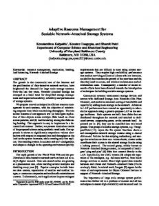
II. BACKGROUND A. DRAM ORGANIZATION Fig. 1 shows a typical DRAM bank which is organized into rows and columns of memory cells, called the DRAM array. Each DRAM bank provides a row buffer that consists of SRAM cells that operate faster than a DRAM array. When data is loaded in the row buffer (row access), a read (RD) or write (WR) command is required to access appropriate column/bytes from the row buffer (column access). Any subsequent accesses to the same row (row buffer hit) will bypass the DRAM array access and the data will be read from the row buffer directly. This concept is referred to as row buffer locality [7]. The access latency of a row buffer miss includes the time to write the contents of the previously opened row, time to activate the row, and the column access time. In case of a row buffer hit, only a read or write command is issued, which only requires column access time. DRAM access latency highly depends on whether an access leads to a row buffer hit or a row-buffer miss. It also depends upon the number of requests en-queued in the DRAM cache scheduler. Request
Read/Write Buffer Hit
MissMap
DRAM cache scheduler
Data
Miss
Access scheduler
Row Address Decoder
Main Memory scheduler
Commands Bank
Bank
...
Bank
Bank
Bank
One Row-Buffer containing one cache set 32 x 64-byte block size = 2048 bytes/row ... Bank Array
29 Data Blocks 3Tag Blocks 6 bytes
RAS
Sense Amplifier
CAS
Row Buffer Column Decoder
Tag Block0
Tag Block1
...
Tag Block29
29 x 6 = 174 bytes
Unused
18 bytes
64 x 3 = 192 bytes
Fig. 1: (a) Tags-In-DRAM (TID)-MissMap DRAM organization [5]
B. STATE-OF-THE ART DRAM-CACHE TAG STORE MECHANISM A primary design consideration for the DRAM cache is the tag size [5, 6]. A 64 MB DRAM cache can store 220 64-byte data blocks, which results in a tag overhead of 6 MB assuming 6 bytes per tag entry [5]. The tags can be stored in a separate SRAM tag array which eliminates DRAM access if the tag array indicates a cache miss. This 6 MB of SRAM tag-store is almost equal to the size of a typical L3 cache used today. Placing all the tags in the SRAM would imply that it has to displace the L3-SRAM cache to stay within the same area. Recent research on DRAM caches provides an efficient and lowoverhead SRAM-based structure named as MissMap [5] that accurately determines whether an access to a DRAM cache will be a hit or a miss. If the MissMap identifies a hit, the request is sent to the DRAM cache scheduler. A MissMap miss (i.e. data is not available in
the DRAM cache) makes DRAM cache misses faster by eliminating the DRAM access before sending the request to main memory. In state-of-the-art DRAM caches [5], the tags are stored in the same row along with the data and indicate the actual location of a data block stored in the row. Fig. 1 illustrates an example for the Tags-In-DRAM (TID)-MissMap approach of [5]. A typical DRAM row size of 2 KB can store up to 32 64-byte blocks. To support TID, the row is partitioned into 29 data blocks (i.e. an associativity of 29 ways per set) and 3 tag blocks (29×6 = 174 bytes). The TID requires three accesses (tag-access, data access, and update replacement information) for a cache hit. These accesses are typically scheduled as compound accesses such that they are fast row buffer hits.
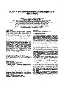
C. INTER-CORE DRAM INTERFERENCE Increased interleaving in the shared DRAM cache from multiple applications executing on a multi-core system can affect system performance in unpredictable ways and it leads to inter-core DRAM interference among the cores which can result in poor system performance via increased latencies. Fig. 2 presents an example showing the latencies for cache requests from applications A and B running on two different cores with shared DRAM cache. Application A has a high LLC access rate with thrashing behavior, while application B has a low LLC access rate with non-thrashing behavior. An applications is said to have thrashing behavior if it exhibits poor locality that generates a large number of fill requests (i.e. data is filled into cache for the first time) without being reused in the future [9, 10]. The large number of cache requests from application A in Fig. 2 (A1, A2 etc.) arrives at the bank earlier than the small number of cache requests from application B (B1 and B2). As a result, cache requests from application B are significantly delayed by this so-called inter-core DRAM interference which can degrade the performance of application B. Inter-core DRAM interference is primarily due to fill requests from thrashing applications. These unnecessary fill requests from thrashing applications may delay the critical (read or write) requests from non-thrashing applications with low DRAM access rate. Contention between critical and unnecessary fill requests increases the amount of time needed to service critical requests. When the intensity of unnecessary fill requests for thrashing applications is high, the benefits obtained by the miss rate reduction of a DRAM cache are reduced. Our adaptive DRAM placement policy (details in Section III.B) attempts to mitigate inter-core DRAM interference by reducing fill requests from thrashing applications. Order of requests sent to DRAM Controller: A1
A2
A3
A4
Legend: B1
Row Buffer Hit
B2
Row Buffer Miss
Service of requests: A1
A2
A3
A4
B1
B2 time
Latency B1
Fig. 2: Example illustrating inter-core interference at the DRAM bank
III. ADAPTIVE CACHE MANAGEMENT IN HYBRID CACHE ARCHITECTURE State-of-the-art DRAM cache hierarchies are composed of up to four levels of on-chip cache with small private L1/L2 caches, intermediate size shared L3-SRAM and high capacity shared L4-DRAM caches [5, 6]. We propose to flatten the cache hierarchy by merging the DRAM into the L3 cache with a large hybrid cache composed of L3SRAM and L3-DRAM. In this section, we introduce our new hybrid cache architecture (HCA). First, we present the HCA organization, then we introduce the hardware-based adaptive DRAM placement
Bank
Bank
…
Bank
Control Dispatcher
L3-SRAM Invalidate Buffer
MissMap (2 MB)
Fill-DRAM Main MemoryRead/Write Buffer
L3-SRAM miss status L3-SRAM handling register Writeback-Buffer
Fill-DRAM
L3-Miss Address
L3-SRAM (6 MB tags + data)
ADPPolicy
LFSRs PSEL counters
L2 Miss / Writeback / Fill / Invalidate
L2 Cache D$ I$ Core 0
L2 Cache I$ D$ Core 1
...
F E A B
F
E A B C
G
G F E A
G
G E A B
H
H G F E
H
G E A B
I
I
H G F
I
I
G E A
J
I
L2 Cache I$ D$ Core n-1
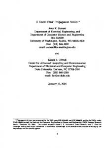
Fig. 3: Our Hybrid cache architecture (HCA); Fill-DRAM is a single bit field that indicates whether an incoming line from off-chip memory should be placed into the L3-DRAM or not; details discussed in Section III.B and III.C
NP
E A B C
F
E A B C
NP
G
E A B C
NP
H
E A B C
NP
I
I
E A B
J
I
G E A
NP
J
I
E A B
NP
A
I
Hit
A
A
I
Hit
I
B
B A
I
G
B
B A
I
E
Hit
E B A J
E
B A
I
G
E
E B A
I
Hit
F B A
I
E B A
I
NP
A J
I
H
RU>5 B RU=7 E
B A J
F E B A
F
Num_fills = 10 Num_hits = 0
(b)
G E
NP
F
Num_fills = 5 Num_hits = 1
(c)
E B
Num_fills = 2 Num_hits = 3
Fig. 4: Our Example illustrating DRAM placement probability of (a) 1, (b) ½, and (c) ¼ (line placement shown as grey, hits shown as shades, NP stands for line not placed in L3-DRAM, RU stands for reuse distance)
Fig. 5 shows the details of our ADP-policy that is based on set dueling. Set dueling is a well established mechanism [4, 10] to adaptively choose between two competing policies P0 and P1. In set dueling, a few sampled sets of the cache are dedicated to always use policy P0 and other few sampled sets to always use policy P1. A saturating k-bit policy selection (PSEL) counter (counting from 0 to 2k-1 and initialized with 2k-1) estimates which of the two policies leads to a smaller number of misses. Misses in the sampled sets using P0 cause the PSEL counter to be incremented and misses in the sampled sets using P1 cause it to be decremented. If the MSB of PSEL is ‘0’, then policy P0 is used for all non-sampled sets, if it is ‘1’, then policy P1 is used. Each row shows 1 set and the 4 numbers per row correspond to the placement probability pi for an insertion of corei to that set
24 104
Cluster
B. ADAPTIVE DRAM PLACEMENT POLICY (ADP-POLICY) Existing DRAM placement policies [3-6] do not work well with applications that have a reuse distance (i.e. the number of insertions before the line is reused) larger than the cache associativity. Such applications are classified as “thrashing” applications [9, 10]. These applications have poor temporal locality for the available cache size that generates a large number of requests without being reused in the future [9, 10]. Fig. 4 illustrates a 4-way L3-DRAM cache with accesses (shown in capital letters E, F etc.) from a thrashing application. On a cache miss, an incoming cache line is placed into the most recently used (MRU) position while the line in the least recently used (LRU) position is the candidate for eviction to make room for the incoming line. The DRAM placement policy used in the state-of-theart [3-6] statically inserts the line with a probability of 1 which increases the number of unnecessary fill requests for thrashing applications as illustrated in Fig. 4-(a). For instance, lines A, B, E and F have a reuse distance (RU) greater than the associativity of 4 and are thus never reused if inserted with a probability of 1 as illustrated in Fig. 4-(a). This causes inter-core DRAM interference (via increased unnecessary fill requests) and reduced number of hits. For thrashing applications, the performance can be improved by placing the cache line into L3-DRAM with a low probability, thus reducing the number of fill requests. It enables thrashing applications to retain some fraction of the working set which increases the number
NP
A B C D E
A
H G
RU>5 A
(a)
LRU
A B C D
RU=1 for line E
F
time
Data
Access Scheduler
L3-DRAM-Read/ Write Buffer
E A B C
RU=7 F Legend:
Bank
Our Contribution Access Scheduler
E
J
Main Memory
Bank
E A B C
L3-DRAM Leader Sets Non-Sampled Sets for all cores
Leader Sets
Leader Sets Non-Sampled Sets for all cores
Probability selection for partial sets
pa pb
0 1
pab,i
MSB(PSEL ab i )
< p0, pa pb pab,0 pc pd pcd,0 pf0 pf0 pf0 pf0 pf0 pf0 pf0 pf0
p1, p2, p3 > pf1 pf2 pf3 pf1 pf2 pf3 pf1 pf2 pf3 pf1 pf2 pf3 pf1 pf2 pf3 pf1 pf2 pf3 pf2 pf3 pa pb pf2 pf3 pab,1 pf2 pf3 pf2 pf3 pc pd pf2 pf3 pcd,1 pf2 pf3 pf1 pa pf3 pf1 pb pf3
Non-Sampled Set:
pf0 pc pd
0 1
pf1 pab,i
MSB(PSEL cd i )
pf2
pf3 pab,i pcd,i
0 1
+
PSEL ab 0
–
+ +
PSEL cd 0
–
MPSEL 0
–
+
PSEL ab 1
–
+ +
PSEL cd 1
–
MPSEL 1
–
+
PSEL ab 2
core0 Sampled Sets
…
A B C D
E
core0 Non-Sampled Sets
L3-DRAM cache Bank
MRU
Access
…
Fig. 3 shows the organization of our HCA where the Last-LevelCache (LLC) is comprised of L3-SRAM and L3-DRAM cache. The MissMap table (functionality explained in Section II.B) is accessed after a miss in the L3-SRAM. A MissMap hit indicates that the line is present in L3-DRAM. In that case, the line is replicated to L3-SRAM to exploit the temporal locality that the referenced line might be accessed again in the near future. Hits to these replicated lines in L3SRAM reduce the effective access latency by avoiding costly L3DRAM accesses, hereby reducing inter-core DRAM interference. On a MissMap miss, the line is brought from memory and installed into L3-SRAM. The line may or may not be filled additionally in L3DRAM, which is determined by our adaptive DRAM placement policy (ADP-policy) (see Section III.B). Existing DRAM cache hierarchies [5, 6] always place the line both into DRAM and SRAM caches.
–
…
A. OUR HYBRID CACHE ARCHITECTURE (HCA)
of hits as illustrated in Fig. 4-(b) and (c). In this example, a placement probability of 1ൗ4 leads to the best hit rate and to reduced number of fill requests compared to higher placement probabilities. To reduce interference between hit requests and unnecessary fill requests in L3-DRAM, our adaptive DRAM placement policy (ADP-policy) uses a low probability to place an incoming line for applications with long reuse distances and uses the highest probability of 1 for applications with short reuse distances. Our ADP-policy adapts the L3DRAM placement probabilities at run-time on a per-core basis.
RU=7 for line E
policy, and finally we show the integration with the inner cache levels.
Probability selection for non-sampled sets
pfi
MSB(MPSEL i )
Legend: Fixed Probabilites Partial Sets Non-Sampled Set
Fig. 5: Details of our ADP-policy as example for a 4-core system
We employ the set dueling mechanism to adaptively choose among four L3-DRAM placement probabilities (pa, pb, pc, and pd). In our ADP-policy each set places an incoming line with a probability vector , where pi denotes the placement probability for requests from corei. Some cache sets are “leader sets” (that contain some sampled sets per core) and other cache sets are “non-sampled sets” that follow the decisions of the leader sets. Fig. 5 shows an example for a quad-core system where the sets are clustered into groups of 128 sets. Each cluster contains 24 leader sets (6 per core) and 104 non-sampled sets. The goal of the ADP-policy is to decide the placement probability pfi for corei at run-time for the large number of non-sampled sets. Out of the 6 leader sets per core, 4 sets (grey boxes in Fig. 5) are dedicated as sampled sets with fixed placement probabilities pa, pb, pc, and pd (we use pa = 1Τ64, pb = 1Τ16, pc = 1Τ4, and pd =1). For example, core0 always places an incoming line with a fixed probability of pa for the first set of each cluster (p0=pa for this set) and with probability pb for the second set of the cluster (p0=pb). The 10-bit saturating policy selection counter ܲܵܮܧ for corei estimates which of the two placement probabilities (pa or pb) leads to the smaller number of misses. A miss incurred in the set dedicated for pa increments ܲܵܮܧ while a miss incurred in the set dedicated for pb decrements ܲܵܮܧ . This direct comparison between pa and pb is used to decide the placement probability pab,i of a so-called “partial set” for corei (shown as shaded boxes in Fig. 5). If the MSB of ܲܵܮܧ is 0, then pab,i is set to pa, otherwise to pb (see multiplexors at the lower part of Fig. 5). Similarly, ܲܵܮܧௗ estimates which of the two placement probabilities pc or pd leads to the smaller number of misses. Finally, a meta-policy selection counter ܮܧܵܲܯ is associated with each corei that estimates which of the two partial placement probabilities (pab,i or pcd,i) leads to the smaller number of misses. If the MSB of ܮܧܵܲܯ is 0, then the placement probability pfi for all nonsampled sets of corei is pab,i, otherwise pcd,i. To realize different placement probabilities, a linear feedback shift register (LFSR) [16] is used that generates a 6-bit pseudo-random number (6-bit LFSR generates a number between 1-63 excluding zero) which is compared to threshold values (‘2’ for pa = 1Τ64, ‘5’ for pb = 1Τ16, ‘17’ for pc = 1Τ4, and ‘64’ for pd = 1). For example the placement probability pb = 1Τ16 requires generating a pseudorandom number and testing whether it is smaller than 5. If this is the case, then the line is placed’ in L3-DRAM, otherwise the line bypasses L3-DRAM. Altogether, our ADP-policy performs an adaptive L3-DRAM placement/bypass decision based on the comparison of the pseudo random number with the adaptive threshold value for pi.
L3-SRAM misses (see Fig. 6). The various fields of the MSHR entry include the Valid-bit, Issued-bit (request is issued or still pending), Access-type (load or store), Value-field (data returned or store value), and Cache-block-address. We add an additional single-bit field to MSHR and to the main memory read/write buffer (MM-RWB) named as Fill-DRAM that indicates whether an incoming line when brought from off-chip memory should be placed into the L3-DRAM or not. For a MissMap hit after the L3-SRAM miss, the dispatcher (see Fig. 3 and Fig. 6) forwards the request to the L3-DRAM access scheduler by allocating an entry in the L3-DRAM read/write buffer (L3-DRAM-RWB). When the data is returned from L3-DRAM, it is forwarded to the requesting core and filled in L1/L2 and L3-SRAM. For a MissMap miss after the L3-SRAM miss, the Fill-DRAM field of the MSHR entry is determined by our ADP-policy as illustrated in Fig. 3 and Fig. 6. The dispatcher forwards the request to the main memory access scheduler by allocating an entry in the MM-RWB. If the Fill-DRAM field of the MSHR entry is 1, the dispatcher additionally allocates an entry in the L3-DRAM-RWB. When the data is returned from main memory to MM-RWB, the Fill-DRAM field of the MM-RWB entry is checked. If the Fill-DRAM field is 1, then the line is forwarded to the respective L3-DRAM-RWB entry so that the line is filled in L3-DRAM. If the Fill-DRAM field is 0, then the line bypasses the L3-DRAM. Independent of the Fill-DRAM field, the data is forwarded to the requesting core and filled in L1/L2 and L3-SRAM. Maintaining Inclusion: In our HCA, inclusion [14, 15] is maintained between the private L1/L2 caches and the aggregation of L3SRAM and L3-DRAM to simplify the implementation of a coherence protocol (non-inclusive caches increase the hardware overhead and verification complexity compared to inclusive caches [15]). Maintaining inclusion implies that a line is invalidated in the private L1/L2 caches when it is evicted from L3. On a private L1/L2 cache miss no snoop needs to be sent to the private caches of the other cores if the L3-SRAM and the MissMap lookup also result in a miss, because then the line is guaranteed to be absent in all private caches. We modify the L3-SRAM and L3-DRAM replacement policies (details below) to maintain inclusion with inner levels of cache.
C. IMPLEMENTATION OF HCA
L3-SRAM replacement policy: If a victim line is evicted from L3-SRAM then the MissMap is accessed to test the availability of the line in L3-DRAM. If the line is absent in L3-DRAM (MissMap miss) then the line is invalidated in the private caches (see Fig. 7) to maintain inclusion. If the line is present in L3-DRAM (MissMap hit), then the line is removed from L3-SRAM without invalidating private caches. Our baseline architecture uses the writeback policy for all cache levels. Each cache maintains one dirty bit per line to record if the line was modified. If it was not modified then it is simply removed from L3-SRAM. Otherwise, the MissMap is checked to determine whether the line exists in L3-DRAM or not. If the dirty victim line resides in L3-DRAM, it is written into L3-DRAM, otherwise it is written to main memory via the L3-SRAM writeback buffer (see Fig. 3). L3-DRAM replacement policy: If a victim line is evicted from L3-DRAM then L3-SRAM is checked. If it is a miss, then the private L1/L2 caches have to be invalidated to maintain inclusion. If L3SRAM is a hit, then the line is simply removed from L3-DRAM
To describe how HCA works along with the ADP-policy, we define the following key events and describe their management: L3-SRAM hit: On an L3-SRAM hit, the hit line is forwarded to the requesting core and filled in core private L1/L2 caches. L3-SRAM Request
L3-SRAM
Allocate miss status handling register (MSHR) entry Miss
Hit
MissMap Hit
ADP-policy (Section III.B)
Miss
Forward hit line to requesting core
Reset Fill-DRAM
Fill private L1/L2
Dispatcher (Section III.C)
No
Place/bypass L3-DRAM? Yes Set Fill-DRAM
Fig. 6: Steps involved in L3-SRAM lookup operation
L3-SRAM miss: On an L3-SRAM miss, a miss status handling register (MSHR) [17] is allocated that keeps track of the outstanding
L3-SRAM Victim line MissMap Hit Line dirty?
Invalidate Line in L1/L2
Miss Line dirty? No
Yes Write back line to L3-DRAM
No
Yes Write back line to main memory Remove line from L3-SRAM
Fig. 7: L3-SRAM replacement policy
D. HARDWARE OVERHEAD Our ADP-policy needs seven LFSRs (six for sampled sets of leader set and one for non-sampled sets; one LFSR requires six XOR gates and six flip flops), three multiplexers and three 10-bit policy selection counters per core to implement the ADP-policy. Altogether, a quadcore system requires 28 LFSR, 12 multiplexers, and 12 10-bit policy selection counters. It requires a single bit per MSHR and MM-RWB entry for the Fill-DRAM field which requires a storage overhead of 64 bits (8 bytes) for a 32-entry MSHR and a 32-entry MM-RWB. Altogether, our proposed scheme comes with negligible hardware overhead.
which combines the benefits of TID-MissMap [5] (by providing low overhead tag-store mechanism) and UCP [11] (that reduces inter-core cache contention). TID-MissMap and TID-MissMap-UCP use a traditional cache hierarchy employing SRAM as L3-cache and DRAM as L4-cache. The main drawback of these approaches is that they statically determine the DRAM placement policy for an incoming line and suffer from inter-core DRAM interference, whereas we propose a hybrid cache architecture (HCA) that adapts the DRAM placement probability at run-time on a per-core basis. We call the configuration using our proposed architecture as TID-MissMap-HCA. HMIPC Improvement
without invalidating private L1/L2 caches and without off-chip traffic (because an updated line is present in L3-SRAM).
IV. EXPERIMENTAL SETUP
TABLE I CORE, CACHE, AND MAIN MEMORY PARAMETERS ROB size 128 MissMap size 2 MB RS size 32 MissMap latency 7 cycles LDQ size 32 SRAM size 8 MB STQ size 24 L3-SRAM size 6 MB Decode width 4 L3-SRAM latency (cycles) 10 cycles Commit width 4 DRAM cache size 64 MB Core Frequency 3.2 GHz DRAM bus width 128 bits L1 Cache 32 KB DRAM-cache banks 8 L2 Cache 256 KB Main memory bus width 64 bits TABLE II APPLICATION MIXES Name Benchmarks Mix_01 433.milc, 437.leslie3d.ref, 471.omnetpp, 473.astar.ref Mix_02 401.bzip2, 437.leslie3d.train, 450.soplex, 473.astar.train Mix_03 473.astar.train, 429.mcf, 437.leslie3d.ref, 462.libquantum Mix_04 437.leslie3d.ref, 437.leslie3d.train, 473.astar.ref, 433.milc Mix_05 462.libquantum, 433.milc, 471.omnetpp, 437.leslie3d.train Mix_06 401.bzip2, 462.libquantum, 433.milc, 433.milc Mix_07 470.lbm, 433.milc, 462.libquantum, 401.bzip2 Mix_08 429.mcf, 450.soplex, 437.leslie3d.train, 462.libquantum Mix_09 462.libquantum, 471.omnetpp,473.astar.train, 437.leslie3d.ref Mix_10 471.omnetpp, 473.astar.train , 450.soplex, 462.libquantum Mix_11 473.astar.train, 470.lbm, 471.omnetpp, 437.leslie3d.ref Mix_12 455.gobmk, 471.omnetpp, 429.mcf, 470.lbm
V. EXPERIMENTAL RESULTS For the evaluation we have compared our approach with the stateof-the-art DRAM cache architecture namely TID-MissMap [5] (discussed in Section II.B) that provides a low-overhead tag-store mechanism. We also compare our approach with the state-of-the-art Utility Cache Partitioning (UCP) [11] scheme applied to L4-DRAM while using TID-MissMap. We call this approach as TID-MissMap-UCP,
TID-MissMap-UCP [11] TID-MissMap-HCA
Fig. 8: Normalized HMIPC improvement relative to TID-MissMap [5]
Fig. 8 shows the normalized harmonic mean instruction per cycle (HMIPC) throughput results for all evaluated configurations with the speedup normalized to TID-MissMap. On average, our proposed TID-MissMap-HCA increases the HMIPC throughput by 23.3% (max 56%) and 13.3% (max 35.1%) compared to TID-MissMap and TIDMissMap-UCP, respectively. a: TID-MissMap [5]
Fraction of DRAM Accesses
Horizontal stacking on an imposer [18] provides an easy way to integrate on-chip DRAM cache with the cores. For this reason, we assume a composition of two stacked dies with one die composed of cores and L3-SRAM while the other die comprises DRAM cache. We use the x86 version of SimpleScalar (zesto) [19] to simulate a quad core system. The core, cache, and main memory parameters are listed in Table I. Off-chip memory timing parameters (in nanoseconds) are based on Samsung K4B510446E-ZCH0 (tCAS=45, tRCD=11.25, tRP=11.25, tRAS=11.25, tRC=11.25). Similar to state-ofthe-art [5], we assume that DRAM-cache timing latencies are approximately half of that compared to off-chip memory, which allows direct comparison with [5]. Our performance evaluations make use of various multi-programmed workloads from SPEC2000 and SPEC2006 [20], as shown in Table II.
60% 50% 40% 30% 20% 10% 0%
100%
abc
b: TID-MissMap-UCP [11]
Demand Hits
Fill Requests
c: TID-MissMap-HCA Writeback Requests
80% 60% 40% 20% 0%
Fig. 9: Distribution of DRAM cache accesses
Fig. 9 shows the distribution of DRAM cache accesses. The three bars per application mix show the different types of DRAM accesses as fraction of all accesses for TID-MissMap, TID-MissMap-UCP, and TID-MissMap-HCA (from left to right). We categorize cache accesses as 1) demand hits for read and write requests, 2) fill requests when the data is filled into DRAM cache for the first time, and 3) writeback requests. On average, our TID-MissMap-HCA increases the percentage of demand hits by 110% (i.e. more than 2u) and 67% compared to TID-MissMap and TID-MissMap-UCP, respectively. On average, our TID-MissMap-HCA reduces the percentage of fill request by 62% and 56% compared to TID-MissMap and TIDMissMap-UCP, respectively. By reducing the intensity of fill requests and increasing the percentage of demand hits using an adaptive DRAM placement probability, we attempt to mitigate a major disadvantage of shared DRAM caches, namely inter-core DRAM interference. Result Analysis: TID-MissMap uses a traditional least recently used (LRU) policy for cache replacement. The LRU policy does not work well with applications that have thrashing behavior and suffers from inter-core cache contention. The thrashing applications insert a large number of lines in the DRAM cache and as a result, they evict useful cache lines belonging to other applications. The eviction of useful cache lines increases the contention between thrashing and non-thrashing applications. TID-MissMap-UCP [11] uses a sophisticated cache partitioning algorithm that efficiently partitions the
Placement Probability
DRAM cache by ways and considers overall misses as an optimization goal. It uses an Utility Monitoring Circuit (UMON) to collect runtime miss rate information of individual applications by allocating less DRAM cache resources (i.e. ways) to thrashing applications, hence reducing inter-core cache contention between thrashing and non-thrashing applications. However, TID-MissMap-UCP still inserts cache lines into DRAM cache with a probability of 1 which causes inter-core DRAM interference by increasing unnecessary fill requests from thrashing applications. The performance improvement of our TID-MissMap-HCA architecture over TID-MissMap-UCP is mainly due to reduced inter-core DRAM interference via our ADP-policy which chooses low placement probabilities for thrashing applications with long reuse distance.
[1]
1
1
[2]
462.libquantum in Mix_05
1/4
1/4
1/16
1/16
1/64
1/64 10
310
610
910
1210
1
[3]
462.libquantum in Mix_06 10
(a) Execution time in Million of cycles
Placement Probability
proposed a hybrid SRAM/DRAM cache hierarchy for multi-core systems that reduces DRAM fill requests from thrashing applications via an adaptive DRAM placement policy, thereby reducing inter-core DRAM interference. We evaluated our hybrid cache architecture for various multi-programmed workload mixes and compared it to stateof-the art. Our experiments show that our proposed scheme increases the performance (harmonic mean instructions throughput) by 23.3% (maximum 56%) and 13.3% (maximum 35.1%) compared to TIDMissMap [5] and TID-MissMap-UCP [11] at negligible hardware overhead.
210
410
610
810
(b) Execution time in Million of cycles
[4]
1 437.leslie3d.ref in Mix_09
1/4
[5]
1/4 470.lbm in Mix_12
1/16
1/16
1/64
1/64 10
210
410
610
(c) Execution time in Million of cycles
[6] 10
310
610
910
1210
(d) Execution time in Million of cycles
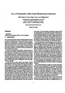
Fig. 10: (a) Runtime DRAM placement probability for the non-sampled sets of (a) 462.libquantum in Mix_05, (b) 462.libquantum in Mix_06, (c) 430.leslie3d.ref in Mix_09, and (d) 470.lbm in Mix_12
Comparing across the applications, we found that the reuse distance of some applications depends upon the mix of the applications (for one mix of applications an application exhibits longer reuse distance while for another mix it exhibits shorter reuse distance). Fig. 10-(a) and Fig. 10-(b) illustrate this observation showing the DRAM placement probability for 462.libquantum in Mix_05 and Mix_06 respectively. We sample the DRAM placement probability once every 10 million cycles. 462.libquantum requires a huge working set size of 29 MB. When running concurrently with 433.milc, 471.omnetpp, and 473.leslie3d.train (Mix_05), 462.libquantum has a low probability to insert the cache line into L3-DRAM because it exhibits longer reuse distance at highest probability of 1. When running concurrently with 401.bzip and two instances of 433.milc (Mix_06), 462.libquantum has the highest probability to insert the cache line into L3-DRAM because it exhibits shorter reuse distance than L3-DRAM associativity. We also found that the reuse distance for some applications change during different phases of the same applications. Fig. 10(a-d) illustrates this observation showing the DRAM placement probability of 462.libquatum in Mix_05 and Mix_06, 437.leslie3d.ref in Mix_09 and 470.lbm in Mix_12 respectively. The DRAM placement probability of these applications changes during different phases of their execution, which shows the fundamental advantage of our adaptive DRAM placement policy in our Hybrid Cache Architecture (HCA).
VI. CONCLUSIONS We identified that inter-core DRAM interference can cause performance degradation in existing SRAM/DRAM cache hierarchies [5, 6] when the cache access rate from multiple applications varies significantly. We found that in order to mitigate inter-core DRAM interference it is necessary to minimize the number of DRAM fill requests from thrashing applications with large working set sizes. We
[7] [8]
[9] [10] [11]
[12] [13] [14] [15] [16] [17] [18] [19] [20]
REFERENCES B. Rogers, A. Krishna, G. Bell et al., “Scaling the Bandwidth Wall: Challenges in and Avenues for CMP Scaling”, SIGARCH Computer Architecture News, vol. 37, no. 3, pp. 371–382, 2009. D. Wendel, R. Kalla, R. Cargoni et al., “The Implementation of Power7TM: A Highly Parallel and Scalable Multi-core High-end Server Processor”, in IEEE Int’l Solid-State Circuits Conf., 2010, pp. 102–103. B. Black, M. Annavaram, N. Brekelbaum et al., “Die-Stacking (3D) Microarchitecture”, in 39th Annual IEEE/ACM International Symposium on Microarchitecture (MICRO), 2006, pp. 469–479. G. H. Loh, “Extending the Effectiveness of 3D–stacked DRAM Caches with an Adaptive Multi-Queue Policy”, in IEEE/ACM International Symposium on Microarchitecture (MICRO), 2009, pp. 174–183. G. H. Loh and M. D. Hill, “Efficiently Enabling Conventional Block Sizes for Very Large Die-stacked DRAM Caches”, in IEEE/ACM International Symp. on Microarchitecture (MICRO), 2011, pp. 454–464. L. Zhao, R. Iyer, R. Illikkal, and D. Newell, “Exploring DRAM Cache Architecture for CMP Server Platforms”, in 25th International Symposium on Computer Design (ICCD), 2007, pp. 55–62. Y. Kim, M. Papamichael, O. Mutlu, and M. H. Balter, “Thread Cluster Memory Scheduling: Exploiting Differences in Memory Access Behavior”, in IEEE/ACM Int’l Symp. on Micro. (MICRO), 2010, pp. 65–76. Y. Kim, D. Han, O. Mutlu, and M. Harchol-Balter, “ATLAS: A Scalable and High-performance Scheduling Algorithm for Multiple Memory controllers”, in 16th IEEE Symposium on High-Performance Computer Architecture (HPCA), 2010, pp. 9–14. Y. Xie and G. H. Loh, “PIPP: Promotion/Insertion Pseudo-Partitioning of Multi-Core Shared Caches”, in 36th International Symposium on Computer Architecture (ISCA), 2009, pp. 174–183. A. Jaleel, W. Hasenplaugh, M. Qureshi et al., “Adaptive Insertion Policies for Managing Shared Caches”, in Int’l Conference on Parallel Architectures and Compilation Techniques (PACT), 2008, pp. 208–219. M. K. Qureshi and Y. N. Patt, “Utility-Based Cache Partitioning: A Low-Overhead, High-performance, Runtime mechanism to Partition Shared Caches”, in IEEE/ACM International Symposium on Microarchitecture (MICRO), 2006, pp. 423–432. X. Wu, J. Li, L. Zhang et al., “Hybrid Cache Architecture with Disparate Memory Technologies”, in 36th International Symposium on Computer Architecture (ISCA), 2009, pp. 34–45. Y. T. Chen, J. Cong, H. Huang et al., “Dynamically Reconfigurable Hybrid Cache: An Energy-Efficient Last-Level Cache Design”, in Design, Automation and Test in Europe (DATE), 2012, pp. 45–50. I. Incorporation, “First the Tick, Now the Tock: Next Generation Intel Microarchitecture (Nehalem)”, in Intel White Paper, March 2008. A. Jaleel, E. Borch, M. Bhandaru et al., “Achieving Non-Inclusive Cache Performance with Inclusive Caches”, in IEEE/ACM International Symposium on Microarchitecture (MICRO), 2010, pp. 151–162. S. Golumb, “Shift Register Sequences”, 1982. D. Kroft, “Lockup-Free Instruction Fetch/Prefetch Cache Organization”, in Int’l Symposium on Computer Architecture (ISCA), 1981, pp. 81–87. Y. Deng and W. Maly, “Interconnect Characteristics of 2.5-D System Integration Scheme”, in International Symposium on Physical Design (ISPD), 2001, pp. 171–175. G. H. Loh, S. Subramaniam, and Y. Xie, “Zesto: A Cycle-Level Simulator for Highly Detailed Microarchitecture Exploration”, in Int’l Symp. on Performance Analysis of Systems and Software (ISPASS), 2009. “Standard Performance Evaluation Corporation”, http://www.spec.org.