Adaptive Coding and Modulation: A Key to Bandwidth-Efficient Multimedia Communications in Future Wireless Systems∗ K. J. Hole and G. E. Øien Department of Telecommunications Norwegian University of Science and Technology N-7491 Trondheim, Norway
Abstract
resource as the number of systems, users, and services increase. If real-time, high-quality multimedia services are to be supported in future wireless systems, there is thus a need for novel transmission schemes—i.e. compression, modulation, error control, and access techniques. The schemes must provide bandwidth-efficient, robust communication with low delay, supporting multiple users on wireless channels. Since time-varying channel conditions—and thus time-varying capacity—is an important feature of wireless and mobile communication systems, future systems should exhibit a high degree of adaptivity on many levels in order to reach these goals [1, 2]. Examples of such adaptivity are: information rate adaption, power control, code adaption, bandwidth adaption, antenna adaption, and protocol adaption. In this paper we focus on the aspects of information rate adaption. The ideas presented are generic in the sense that they might be exploited both in fixed wireless access and satellite communications, as well as in fourth generation (4G) mobile cellular systems. The rest of the paper is organized as follows. Section 2 models a single-user wireless fading channel, while Section 3 discusses the channel (Shannon) capacity and argues why the coding and modulation scheme should be adaptive. Section 4 introduces techniques for designing and analyzing rate-adaptive schemes. A multi-user cellular network utilizing adaptive coding and modulation on the wireless links is modelled in Section 5. The spectral efficiency of a particular adaptive scheme is presented in Section 6 for both the single-user and multi-user models. Section 7 concludes the paper and gives an overview of future research.
This paper gives an introduction to adaptive coding and modulation, and explains its potential in wireless communications over time-varying fading channels. If accurate channel modelling and channel state estimation can be performed, the average information rates (measured in transmitted information bits per second) might be significantly increased by the use of rate-adaptive transmission. Current theory predicts an increase in achievable average information rates of several hundred % over today’s systems for the same number of users and the same overall bandwidth. We show results for a practical adaptive coding scheme applied to some well-known flat-fading channel models. An important performance measure discussed is average bandwidth efficiency (information rate per unit bandwidth) vs. bit-error-rate. Both single-user links and multi-user microcellular networks are used as examples of what might be achieved by a properly designed adaptive transmission scheme. The examples indicate that rate-adaptive transmission can provide the large information rates needed to support high-quality multimedia services in future wireless systems.
1
Introduction and motivation
Wireless access, e.g. to the Internet, may in the future replace many fixed-wire connections in telecommunications. Wireless technology can be rolled out rapidly, thus bypassing the need for installation of new cables. The technology also encourages mobility, allowing people on the move to access interactive multimedia services such as video conferencing, e-commerce, location services, and (network) computer games. An acceptable quality of service for future multimedia services (e.g. high audio and video quality, high reliability, strict real-time constraints) can only be achieved by realizing much higher information rates than those available in today’s wireless systems. At the same time, bandwidth is becoming an ever-scarcer
2
Wireless channels
The signals transmitted on wireless channels are subjected to a number of impairments, notably reflections, attenuation, and scattering of power. Wireless channels are thus typically characterized by multipath transmission of the signal, i.e., the received signal results from summation of different replicas of the original signal. Each replica has its own particular amplitude attenuation and delay, which varies with time.
∗ Questions regarding this paper may be e-mailed to Hole at
[email protected] or Øien at
[email protected].
1
This leads to time-varying signal strength and signal fading. In the following, we give some background on the modelling techniques used for wireless channels. We will focus on narrowband channels with frequencyindependent or flat fading [3].
2.1
In the case of an NMF channel, the fading envelope1 α has a so-called Nakagami-m distribution, which causes the received CSNR to become gamma distributed with PDF pγ (γ) =
Narrowband radio channels
Pr (k) , Pn (k)
3
α2 (k) · P N0 B
(1)
(2)
with E[γ(k)] = γ = GP/(N0 B) where G = E[α2 (k)] is the average received power attenuation.
2.2
¶m
¶ µ γ m−1 γ , γ ≥ 0. exp −m Γ(m) γ
(3)
What to learn from information theory
Information theory tells us that any communication channel is characterized by a maximal information rate, the channel capacity, which provides the ultimate upper limit for when reliable transmission is possible [4]. For any given channel with a certain average CSNR, this channel capacity is a constant number, regardless of how strict the demands on bit-error-rate (BER) may be. This number has come to represent the “holy grail” for designers of bandwidth-efficient transmission schemes. It may be stated as the maximal average number of information bits which may be carried per transmitted channel symbol, or—if multiplied by the maximum (Nyquist) channel symbol rate—as the maximal average number of information bits per second. For any information rate we may choose to specify below the channel capacity, theory tells us that there always exists a transmitter and a receiver which are able to communicate at this rate with arbitrarily low BER. For rates above the capacity, we can be sure that no such transmitter-receiver pairs exist. Of course, finding the optimal transmitter-receiver pair may be a very complex task even if the specified information rate lies below capacity. Also, even if found, the capacity-achieving transmitter-receiver pair may be extremely complex to implement. Most current-day communication systems thus operate at rates significantly less than the theoretical capacity, although the advent of modern error-control coding schemes have decreased the gap between theory and practice considerably for some channels, and almost closed it in some special cases.
where Pr is the received signal power and Pn is the received additive noise power. The CSNR is often the most useful way of describing the channel’s state. We shall assume that a constant average transmit power P [W] is used, and that the two-sided power spectral density of the AWGN is N0 /2 [W/Hz]. For a given channel bandwidth B [Hz], we then have γ(k) =
m γ
Here, m ≥ 1/2 is the Nakagami fading parameter, restricted in this paper to be an integer, and Γ(m) is the Gamma function, equal to Γ(m) = (m − 1)!. The Nakagami fading parameter can be loosely interpreted as the ratio between received line-of sight signal power and received signal power from scattering and reflections. In other words, the higher m is, the more lineof-sight power dominates, making for a better channel less prone to deep fades.
Narrowband radio channels are often represented by stochastic flat-fading channel models—such as Rayleigh, Rice, or Nakagami fading [3]. The models are described simply by a probability density function (PDF) for the fading amplitude, and the fading correlation properties. We shall make use of the well-known complex baseband model. Denoting the transmitted complex baseband signal at time index k by x(k), the received signal after transmission on a flat-fading channel can be written as y(k) = α(k) · x(k) + w(k). Here, α(k) is the fading envelope and w(k) is complex-valued additive white gaussian noise (AWGN) with statistically independent real and imaginary components. The fading envelope (α(k)) is a complex stochastic variable representing the resultant gain after summing all received signal components (line-of-sight, reflected, and scattered) at the receiver. In this paper we shall assume that the receiver is able to perform perfect coherent detection, effectively performing perfect phase compensation and thus turning α(k) into a real variable. In general, the received channel signal-to-noise ratio (CSNR) at a given time k is defined as γ(k) =
µ
Nakagami multipath fading: A general flat-fading channel model
Of special interest is the so-called Nakagami multipath fading (NMF) model [3]. This is a very general statistical model covering or approximating a lot of interesting special cases, including the more well-known Rayleigh and Rice fading channels. The NMF model has been empirically shown to be able to provide a good fit to the fading experienced in a wide range of real-world wireless channels.
1 We suppress the time dependence from now on for the sake of notational simplicity.
2
3.1
Information theory for wireless channels
Encoder 1
Encoder 2
Encoder N
x(k)
.
+
α(k)
CSNR
y(k)
w(k)
Decoder 2
. . .
. . .
Claude Shannon developed the general theory behind channel capacity and derived famous formulas for some important channel models, most notably the AWGN channel [4]. However, for wireless channel models, closed-form capacity formulas, and the design of efficient transmission schemes approaching the capacity, have remained elusive—until the last 5 years or so. In [5], Goldsmith and Varaiya derived the channel capacity of a single-user flat-fading channel with arbitrary fading distribution, when perfect channel state information (CSI) is available both at the transmitter and the receiver. The CSI needed by the transmitter is the CSNR γ. For a general flat-fading channel where the CSNR has PDF pγ (γ), the capacity is given by Z log2 (1 + γ)pγ (γ) dγ [bits/s] (4) C=B all γ
Decoder 1
Decoder N
γ
Figure 1: Rate-adaptive transmission.
rate. One must then choose a particular set of discrete channel signal constellations, e.g. quadrature amplitude modulation (QAM) constellations of varying size [8]. For coded transmission, one must also choose a particular set of channel (error control) codes. The transmitter will then switch between signal constellations (and, in the case of coded transmission, channel codes) of varying size/rate at discrete time instances. At any given time, the transmitter chooses symbols when fixed average transmit power is assumed. from the largest constellation meeting the BER reAlouini and Goldsmith [6] used this result to deter- quirements with the available CSI, thus ensuring maxmine a closed-form expression for the capacity per unit imum spectral efficiency for the given acceptable BER. bandwidth, or maximum average spectral efficiency There are different kinds of adaptive coding schemes (MASE), of an NMF channel [9]–[17]. Hereafter, we shall use the term adaptive coded modulation (ACM) as a collective term for all ¶k µ ¶ m−1 µ em/γ X m m C variants. As mentioned earlier, the CSNR determines = Γ −k, [bits/s/Hz] , (5) the channel state at a given time. For any discrete B ln(2) γ γ k=0 ACM scheme, the CSNR must be periodically estiwhere Γ(·, ·) is the complementary incomplete Gamma mated at the receiver end. We assume that this esfunction [7]. This function is commonly available in timation can be done without error. The set [0, ∞i of possible CSNR values is divided into N + 1 nonnumerical software. To any channel capacity corresponds some specific overlapping intervals or “quantization bins”. At any transmission scheme, the so-called capacity-achieving given time the estimated CSNR will fall in one of these transmission scheme for the channel under discussion. bins, and the associated bin index n ∈ {0, . . . , N }, is This is the scheme that must be used if we are to sent to the transmitter via a feedback channel, which actually fully exploit the capacity. Goldsmith and is assumed error free (see Figure 1). The fading is Varaiya [5] showed that the channel capacity of an assumed slow enough that the CSNR can be viewed arbitrary flat-fading channel with constant average as constant over the time used to estimate and transtransmit power can be approached using a certain mit the CSI. The CSI used by the transmitter can adaptive transmission scheme. This very fact consti- therefore be assumed to be correct at all times.2 When N is large, the CSNR is approximately contutes the main motivation behind the study of rateadaptive coding and modulation. To achieve capacity, stant within each bin, and the channel can be approxthe signal constellation size, and hence the informa- imated by an ordinary AWGN channel for each n. tion rate, must be continuously updated according to Assume that γ ∈ [0, γ1 i in bin 0, γ ∈ [γ1 , γ2 i in bin 1, the channel quality, as measured by the CSNR γ. The . . ., γ ∈ [γN , ∞i in bin N . Also assume that the BER transmission rate should be high when the CSNR is must never exceed a target maximum BER0 . Hence, high, decreasing smoothly as the CSNR decreases. A when γ ∈ [γn , γn+1 i the ACM scheme may use a code block diagram depicting the main principles of a rate- designed to achieve a BER ≤ BER0 on an AWGN adaptive scheme is given in Figure 1. Observe that channel of CSNR ≥ γn . We will show how to deterthe active encoder-decoder pair is determined by the mine the bin boundaries {γn } in the next section. An ACM scheme stops transmitting when the CSNR at the receiver. CSNR γ falls in the bin [0, γ1 i simply because the
3.2
Practical modifications
2 In some situations this assumption breaks down, as e.g. in the case of high terminal speeds (leading to high Doppler shifts and small fading correlation). The assumption is also less accurate the higher the carrier frequency used, a fact which will influence future wireless systems.
The theoretically optimal scheme described in the previous section must in practice be approximated by schemes using discrete updating of the information 3
Inserting this result in (6), we may explicitly compute the ASE of the overall scheme for any specific set of codes (see [17] for a detailed example).
channel quality is too bad to successfully transmit any information with the available codes. When γ < γ1 , the ACM scheme experiences an outage during which information must be buffered at the transmitter end.
4.2
4
ACM analysis and design
In general, it is necessary to implement N encoderdecoder pairs to realize an ACM scheme. However, when the ACM scheme utilizes QAM modulation in conjunction with a type of error control codes called trellis codes [18]–[22], a single encoder-decoder pair exists that can execute the encoding and decoding of all N codes [12, 17]. We therefore concentrate on ACM with QAM trellis codes in the following. A trellis encoder consists of a binary encoder followed by a bit converter mapping the coded bits to a QAM constellation. Consider the encoding of code n in the ACM scheme. At every Lth channel time index, k = L · t, t = 0, 1, 2, . . ., the binary encoder takes as input L · in − 1 information bits and outputs L · in coded bits, L ∈ {1, 2, 3, . . .}. Every block of coded bits is subsequently mapped by the bit converter to a sequence of L channel symbols, each taken from a QAM constellation of Mn = 2in signal points. The maximum spectral efficiency of this code can be seen [17] to be Rn /B = in − 1/L [bits/s/Hz]. The L two-dimensional QAM symbols generated at each time index k can be viewed as one 2Ldimensional symbol, and for this reason the generated code is said to be a 2L-dimensional trellis code. The ACM schemes described in [12, 13, 16] utilize sets of two-dimensional (L = 1) trellis codes, while the ACM scheme described by Hole and Øien [17] may also utilize sets of multidimensional (L > 1) trellis codes, i.e., in practice codes with dimensions 4, 6, and 8. Multidimensional trellis codes are of particular interest since some such codes offer a significantly better performance/complexity tradeoff than two-dimensional codes [21].
In this section, we describe techniques for designing and analyzing ACM schemes. It is assumed that a set of N transmitter-receiver pairs, denoted as transmitter-receiver pair n = 1, . . . , N , is available. Transmitter n has a rate of Rn information bits per second, such that R1 < R2 < . . . < RN . Transmitterreceiver pair n is to be used when γ falls in the CSNR interval [γn , γn+1 i.
4.1
Average spectral efficiency
The average spectral efficiency (ASE) of a transmission scheme is equal to R/B [bits/s/Hz] where R [bits/s] is the average information rate. For a system which adaptively switches between N channel codes, R/B is thus the expected value of the individual codes’ spectral efficiency with respect to the probability distribution {P (γn ≤ γ < γn+1 )}N n=1 : N X R Rn = · P (γn ≤ γ < γn+1 ) [bits/s/Hz] . (6) B B n=1
We see that we need to determine the bin boundaries {γn } that ensure BER ≤ BER0 in order to find the probabilities and thus the ASE. To do this, we invoke the following fact: When a given code, say code n, is operating on an AWGN channel of CSNR γ, the BER-CSNR relationship when the CSNR is varied turns out to be well modelled by an expression of the form [17]: ¶ µ bn γ . (7) BER ≈ an · exp − Mn Here, Mn is the number of signal constellation points and an and bn are constants depending on the code’s weight distribution. These constants can be found for any given code by least-squares curve fitting of data from AWGN channel simulations to (7). The curve fitting must be done separately for each individual code in the set. Assuming that this has been done, and using (7) with equality for a given target BER0 , the bin boundaries are found as γn
=
γN +1
=
Mn K n , bn ∞
n = 1, 2 . . . , N
The choice of codes
5
ACM in microcellular networks
Most researchers have considered ACM in single-user communications systems. However, wireless systems must support a large number of users. The authors [23] have analyzed the performance of ACM in an urban microcellular network with a large number of active users, where each individual wireless link is modelled as a narrowband fading channel. Specifically, we have investigated the use of ACM in outdoor urban microcellular networks of the “Manhattan” type [3]. The principles are transferable to other cellular network topologies as well, with relatively minor modifications to the mathematical techniques used to model the network and to assess the resulting system performance. The situation described here thus serves as an illustrative example of the kind
(8)
where Kn = − ln(BER0 /an ). Manipulations then give ³ ´ ³ ´ mγn+1 n Γ m, mγ − Γ m, γ γ P (γn ≤ γ < γn+1 ) = . (m − 1)! (9) 4
c) interference from other links.3 In addition there is a deterministic power loss, or path loss, due to the decay in the intensity of a radio wave propagating in space. The impairments of the uplinks in a cell are modelled for the worst- and best-case configurations of interfering MSs in neighboring cells (see [23] for a detailed definition of these configurations of interfering MSs). Without going into further detail, it is possible to show that the instantaneous received carrierto-interference ratio (CIR) at the BS is approximately log-normally distributed [23]. Given this model, adaptive coding schemes may be devised, optimized, and analyzed. As a performance measure, we initially use the average link spectral efficiency (ALSE), defined as follows
of modelling techniques that must be used and what performance to expect. Our Manhattan network model consists of uniformly spaced quadratic cells, denoted microcells because their width, D [m], is assumed to be no more than 1000 m. We refer to Figure 2 for an illustration. Each cell has a base station (BS) located at its
A
B
A
B
A
B
A
B
A
B
A
B
A
B
A
ALSE =
R B
[bits/s/Hz]
(10)
where R [bits/s] is the information rate of the adaptive scheme, averaged over all CIRs, and B [Hz] is the effective bandwidth used per link in a cell. If there are U serviced MSs in a cell and the total available uplink bandwidth in the cell is W [Hz], we have B = W/U . Because of the signal path loss, the expressions obtained for the ALSE in [23] is a function of the distance between the transmitting MS and the receiving BS. The available ALSE is higher the shorter this distance is, because the average CIR is then higher. The careful network modelling carried out in [23] Figure 2: Idealized model of wireless Manhattan netallows us to show that any spectrally efficient scheme work consisting of square cells with length D ≤ 1 for Manhattan networks must be able to operate over km. The dark squares represent tall buildings and a large range of CIR values. This is the reason why it the space between the dark squares represent streets. is possible to obtain a larger spectral efficiency with an adaptive coding scheme than with a nonadaptive center. A vehicle-mounted or portable mobile station coding scheme with the same overall transmission de(MS) may be positioned anywhere in the streets, but lay. not inside any of the buildings. Since urban centers To determine the cellular layout of a Manhattan typically contain a large number of active MSs, we as- network, the available frequency spectrum is first disume that the cellular network model is fully loaded, vided over one cluster of adjacent cells such that the i.e. the cells’ communication links are all fully used. individual cells in the cluster utilize different sets of The same set of carrier frequencies is used in each carrier frequencies. The complete network is then obcell labeled A in Figure 2. A different set of carrier tained by deploying many copies of the cell cluster. frequencies is used for all cells labeled B. When an For the complete network, the average area spectral MS in a cell accesses the network it is assigned two efficiency (AASE) provides a measure of the spectral different carriers, one for the downlink (BS-to-MS) efficiency. The AASE is measured in [bits/s]/[Hz · m2 ] and one for the uplink (MS-to-BS). Since the battery and is defined as power of the MS is severely limited compared to the ALSE [bits/s]/[Hz·m2 ] (11) AASE = available power at the stationary BS, the ability of the K ·A MS to transmit data over the uplink is much less than the ability of the BS to transmit over the downlink. where K is the number of cells in the cluster, and We have therefore concentrated on the study of the A is the area of one single cell. As an example, the network in Figure 2 has K = 2. The cell area may be uplinks in fully loaded networks. 2 The networks under study might use frequency- approximated by A = D . We have approximated the AASE for ACM in Mandivision multiple access (FDMA) or time-division multiple access (TDMA). The link signals are de- hattan networks, and shown how the AASE is influgraded by three random phenomena: a) multipath enced by the cellular layout. The reader is referred to 3 Note that AWGN is disregarded since it is typically less fading, modelled by a Nakagami-m PDF, b) shadowing, a slow variation of the received signal mean, and important than the other impairments. B
A
B
A
B
A
A
B
B
A
D
5
6.2
[23] for a more in-depth discussion, and to the next section for some sample results.
6
Cellular systems
Consider the link between an MS, called the desired MS, and its BS in the Manhattan network model. The other transmitting MSs in the fully-loaded network are the interfering MSs.
A practical ACM scheme
This section presents results for a specific ACM scheme based on a set of 8 different 4-dimensional trellis codes utilizing QAM signal constellations with 4, 8, 16, 32, 64, 128, 256, and 512 signal points. The example scheme is based on the International Telecommunications Union’s ITU-T V.34 modem standard (see [17] for more details). The target BER used is BER0 = 10−3 .
8 7 6 ALSE
5 4 3
6.1
Single-user systems
2 400
Figure 3 shows the ASE (6) of the example scheme as a function of the average CSNR γ in dB for various values of the Nakagami parameter m (m = 1 corresponding to Rayleigh fading). As can be seen, the
500
100 600
200 r
700 300 800 400
D
900 500
1000
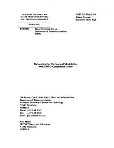
Figure 4: ALSE [bits/s/Hz] as a function of D [m] and r [m].
The ALSE (10) of the MS-to-BS link is plotted in Figure 4 for the worst-case interference configuration. Here, D [m] is the length of the square cells and r is the distance between the desired MS and its BS. As an example, consider the case when D = 1000 m and r is less than 100 m. We have that the ALSE > 7.75 bits/s/Hz, i.e. the ALSE is much larger than in today’s systems. In general, for a fixed length D of the cells, the ALSE decreases with growing distance r between the desired MS and its BS. When we keep r fixed, the ALSE decreases with shrinking D, i.e. smaller cell size. There are large differences in the ALSE values: When r = 20 m and D = 1000 m, the ALSE has value 8.5 bits/s/Hz; for r = 200 m and D = 400 m the ALSE is 1.2 bits/s/Hz. The reuse distance, R [m], is the minimum distance between two BSs that are within line-of-sight of each other and that use the same set of carrier frequencies for the MS-to-BS links. We define the normalized reuse distance as Rn = R/D. It can be seen that the normalized reuse distance is equal to the cluster size K of a Manhattan network. However, while K is a positive integer, we view the normalized reuse distance as a positive real number since this makes it easier to show how the AASE (11) varies with the cluster size. The AASE is plotted as a function of the normalized reuse distance Rn in Figure 5. The distance between the desired MS and its BS is equal to the maximum possible value r = D/2. The plot contains four pairs of curves, one pair for each value of D ∈ {400, 600, 800, 1000}. For a given pair, the upper curve is the AASE for the best-case interference
Figure 3: ASE as a function of the average CSNR [dB] for various Nakagami fading parameter values.
ASE for a given CSNR is much higher than in today’s conventional, nonadaptive coding schemes for wireless links, e.g. GSM with constant spectral efficiency less than one regardless of the average CSNR. Comparing our results to those of other researchers is not always straightforward. Goldsmith and Chua [12], for example, use adaptive transmit power as well as rate adaption, whereas the transmit power is constant in our system. However, it can be seen that in the special case of Rayleigh fading, our example scheme provides an ASE increase of about 0.5 bits/s/Hz compared to the uncoded, constant-power, rate-adaptive QAM scheme of Alouini and Goldsmith [11]. Furthermore, comparing with the expression in (5) we find that the difference between the MASE and ASE of our example scheme is less than 1.9 bits/s/Hz [17]. 6
parallel narrowband subchannels with flat fading [24]. Adaptive coding techniques may be utilized on each individual narrowband subchannel to achieve broadband OFDM transmission with large total average spectral efficiency. The success of ACM/OFDM is ultimately dependent on reliable knowledge of the subchannel dynamics at the transmitter. Since the subchannel states have to be estimated at the receiver, there will always be a certain degradation of system performance compared to the idealized case of perfect subchannel knowledge. It is important to minimize this degradation by finding optimal subchannel estimation techniques for realistic channel models. In November 2000, the authors started a new project with the title “Bandwidth-Efficient and Adaptive Transmission Schemes for Wireless Multimedia Communications” (BEATS). The BEATS project is a part of the IKT-2010 research programme funded by the Norwegian Research Council. The principal objective of this project is to develop bandwidthefficient, adaptive OFDM schemes for broadband wireless multimedia communications. More information about the project may be found on the web-page: http://www.tele.ntnu.no/beats/. As new results become available, they will be posted on this page. The authors also participate in the joint NTNUTelenor research project “Turbo Codes, Access, and Network Technology” (TURBAN). Our TURBAN project goal is to determine efficient channel codes for use in adaptive transmission.
10
D=400 8
6 AASE
D=600 4 D=800
2 D=1000
0 2
4
6
8
10
Normalized reuse distance
Figure 5: AASE [bits/s/Hz/km2 ] as a function of the normalized reuse distance Rn when r = D/2 and D ∈ {400, 600, 800, 1000}.
configuration, while the lower curve is the AASE for the worst-case interference configuration. We observe that as Rn increases, the difference in AASE between the best- and worst-case interference configurations goes to zero. For the best-case interference configuration, the AASE has maximum value for Rn = 2 when D ∈ {600, 800, 1000} and Rn = 3 for D = 400. Unfortunately, the difference in AASE between the best- and worst-case interference configurations is very large for Rn = 2. Hence, Rn = 3 is a better choice. In other words, for the example ACM scheme, a cell cluster should consist of at least three cells using different sets of carrier frequencies.
7
References [1] H. Meyr, “Algorithm design and system implementation for advanced wireless communications systems,” Proc. International Zurich Seminar on Broadband Communications (IZS’2000) (Zurich, Switzerland, Feb. 2000).
Conclusion and further research
[2] V. Bose, D. Wetherall, and J. Guttag, “Next century challenges: RadioActive Networks,” Proc. ACM/IEEE International Conference on Mobile Computing and Networking (MOBICOM’99) (Seattle, WA, Aug. 1999).
The results presented in this paper indicate that it is possible to obtain a much larger spectral efficiency in wireless systems than achieved in present-day systems. The large increase in spectral efficiency may be obtained by utilizing coding schemes which adapt the information rates according to the quality of the wireless links. This in turn may enable the introduction of novel bandwidth-intensive multimedia services.
7.1
[3] G. L. St¨ uber, Principles of Mobile Communication. Norwell, MA: Kluwer Academic Publishers, 1996. [4] T. M. Cover and J. A. Thomas, Elements of Information Theory. New York: John Wiley & Sons, 1991.
Planned research
[5] A. J. Goldsmith and P. P. Varaiya, “Capacity of fading channels with channel side information,” IEEE Trans. Inform. Theory, vol. 43, pp. 1986– 1992, Nov. 1997.
While we have only considered narrowband channels with frequency-flat fading, adaptive coding techniques may also be used on broadband frequency-selective fading channels. Orthogonal frequency division multiplexing (OFDM) can be used to decompose a broadband frequency-selective fading channel into a set of
[6] M.-S. Alouini and A. J. Goldsmith, “Capacity of Nakagami multipath fading channels,” 7
Proc. 47th IEEE Vehicular Technology Conference (VTC’97) (Phoenix, Arizona, May 1997), pp. 358-362.
[18] G. Ungerboeck, “Channel coding with multilevel/phase signals,” IEEE Trans. Inform. Theory, vol. IT-28, pp. 55–67, Jan. 1982.
[7] I. S. Gradshteyn and I. M. Ryzhik, Table of Integrals, Series, and Products. San Diego, CA: Academic Press, fifth ed., 1994.
[19] G. Ungerboeck, “Trellis-coded modulation with redundant signal sets–Part I: Introduction,” IEEE Commun. Mag., vol. 25, pp. 5–11, Feb. 1987.
[8] W. T. Webb and L. Hanzo, Modern Quadrature Amplitude Modulation. Graham Lodge, London: Pentech Press, 1994.
[20] L.-F. Wei, “Trellis-coded modulation with multidimensional constellations,” IEEE Trans. Inform. Theory, vol. 33, pp. 483–501, July 1987.
[9] W. T. Webb and R. Steele, “Variable rate QAM for mobile radio,” IEEE Trans. Commun., vol. 43, pp. 2223–2230, July 1995.
[21] A. Chouly and H. Sari, “Six-dimensional trelliscoding with QAM signal sets,” IEEE Trans. Commun., vol. 40, pp. 24–33, Jan. 1992.
[10] A. J. Goldsmith and S.-G. Chua, “Variablerate variable-power MQAM for fading channels,” IEEE Trans. Commun., vol. 45, pp. 1218–1230, Oct. 1997.
[22] S. S. Pietrobon and D. J. Costello, Jr., “Trellis coding with multidimensional QAM signal sets,” IEEE Trans. Inform. Theory, vol. 39, pp. 325– 336, March 1993.
[11] M.-S. Alouini and A. J. Goldsmith, “Adaptive M-QAM modulation over Nakagami fading channels,” Proc. 6th Communications Theory Mini-Conference (CTMC VI) in conjunction with IEEE Global Communications Conference (GLOBECOM’97) (Phoenix, Arizona, Nov. 1997), pp. 218–223.
[23] K. J. Hole and G. E. Øien, “Spectral efficiency of adaptive coded modulation in urban microcellular networks,” to appear in IEEE Trans. Veh. Technol., paper may be obtained at http://www.tele.ntnu.no/beats/. [24] R. Van Nee and R. Prasad, OFDM for Wireless Multimedia Communications. Artech House Publishers, 2000.
[12] A. J. Goldsmith and S.-G. Chua, “Adaptive coded modulation for fading channels,” IEEE Trans. Commun., vol. 46, pp. 595–602, May 1998. [13] V. K. N. Lau and M. D. Macleod, “Variable rate adaptive trellis coded QAM for high bandwidth efficiency applications in Rayleigh fading channels,” Proc. 48th IEEE Vehicular Technology Conference (VTC’98) (Ottawa, Canada, May 1998), pp. 348–351. [14] T. Ue, S. Sampei, N. Morinaga, and K. Hamaguchi, “Symbol rate and modulation levelcontrolled adaptive modulation/TDMA/TDD system for high-bit-rate wireless data transmission,” IEEE Trans. Veh. Technol., vol. 47, pp. 1134–1147, Nov. 1998. [15] D. L. Goeckel, “Adaptive coding for time-varying channels using outdated fading estimates,” IEEE Trans. Commun., vol. 47, pp. 844–855, June 1999. [16] Y. M. Kim and W. C. Lindsey, “Adaptive codedmodulation in slow fading channels,” J. Commun. and Networks, vol. 1, pp. 99–110, June 1999. [17] K. J. Hole, H. Holm, and G. E. Øien, “Adaptive multidimensional coded modulation over flat fading channels,” IEEE J. Select. Areas Commun., vol. 18, pp. 1153–1158, July 2000. 8