tension along the string is assumed to be spatiotemporally varying. ... boundary control scheme for an axially moving string system, where ..... 0.25 N/m/s. T.
ICROS-SICE International Joint Conference 2009 August 18-21, 2009, Fukuoka International Congress Center, Japan
Adaptive control of an axially moving string under spatiotemporally varying tension via a hydraulic actuator Quoc Chi Nguyen, Quang Hieu Ngo, and Keum-Shik Hong School of Mechanical Engineering, Pusan National University, Busan 609-735, Korea (Tel: +82-51-510-1481, 2454; E-mails: {nqchi, nqhieu, kshong}@pusan.ac.kr) Abstract: This paper presents an adaptive boundary control to suppress the transverse vibrations of an axially moving string by using a hydraulic actuator equipped with a damper, which is located at the right boundary of the string. The tension along the string is assumed to be spatiotemporally varying. The governing equations take the form of coupled partial differential equation and ordinary differential equation (ODE), in which the ODE describes the dynamics of the hydraulic actuator. An adaptive boundary control law is derived using Lyapunov’s direct method and the back stepping technique. Adaptation laws updating unknown system parameters online are included. The effectiveness of the proposed adaptive boundary control is demonstrated through simulations. Keywords: Axially moving string, Lyapunov method, adaptive control, partial differential equation, spatiotemporally varying tension
1. INTRODUCTION
and unknown boundary disturbance. They assumed that some constants which are related to the varying tension i.e. lower bound, upper bound and their derivates are a priori known. Adaptation laws are derived to estimate the density of the string and unknown disturbance. The asymptotic stability has been proved by using semi group theory. Chen et al. [6] designed an adaptive control law to achieve vibration reduction of an axially moving string via a tensioner that can be considered as a boundary control actuator. They assumed that tension of the moving string and parameters of the tensioner are unknown and constant. All unknown parameters appear in the ordinary differential equation that describes the dynamics at the right boundary of the string. Motivated by [5], this paper investigates an adaptive boundary control of an axially moving system under a varying tension and unknown parameters which appear in both the string and the boundary actuator. In this paper, we consider an axially moving string system modeled by a coupled partial and ordinary differential equations (PDE and ODE), in which a mechanism consisting of a hydraulic actuator and a damper is assembled at the right boundary shown in Fig.1. The main objective of this paper is to achieve transverse vibration suppression of the axially moving string by adaptive boundary control. The control force is applied to the string through the hydraulic actuator by updating the unknown parameter values of the actuator adaptively.
In mechanical engineering, many processes are modeled as an axially moving system. For instance, power-transmission belts, plastic films, chain drives, high-speed magnetic tapes, paper sheets under processing, and steel strips are a few examples. In these systems, the mechanical vibrations (particularly in the transverse direction) of the moving part become the main cause that limits their utility, especially in high-speed precision systems. Thus, how to reduce the transverse vibrations of axially moving systems is an important research area. To achieve a solution for this problem, many researchers focused on active vibration control methods. The boundary control is known to be effective in reducing the transverse vibration of axially moving string, beam, and belt systems [1-13]. The important property of this approach is that actuation and sensing is performed on the same boundary. By using a Lyapunov function, which is equivalent to the total mechanical energy of the moving system, the control law is derived. The boundary control law includes the transverse motion of the moving material and its slope rate at the boundary. In practice, the data used in the boundary control law can be measured by adding sensors at the boundary. Li et al. [1, 2] introduced an adaptive vibration isolation scheme for axially moving beams, which are divided into two spans by a transverse force actuator, to regulate the transverse vibration of the controlled span to zero asymptotically under bounded disturbances in the uncontrolled span. Fung et al. [3, 4] developed a boundary control scheme for an axially moving string system, where adaptive boundary control laws are employed to suppress vibrations through a mass-damper-spring mechanism and to update online the estimation values of unknown parameters. Yang et al. [5] presented an adaptive boundary control of an axially moving system under spatiotemporally varying tension
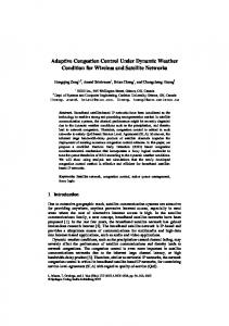
2. PROBLEM FORMULATION Fig. 1 shows the axially moving string system with a hydraulic touch roll actuator located at the right boundary. The left boundary is fixed in the sense that the movement of this boundary in the vertical direction is neglected. Conversely, at the right boundary, a transverse movement occurs under the effect of the hydraulic actuator and the damper.
- 293 -
PR0002/09/0000-0293 ¥400 © 2009 SICE
is regulated to decay to zero. Which requires that there exists a solution w( x, t ) � 0 as t � � . For convenience, instead of wx �x, t � and wt �x, t � , wx and wt will be used, and similar abbreviations will be used in the sequel. To implement the boundary control algorithm, the parameters of the system have to be provided. The actuator displacement w�l , t � and the slope wx �l , t � can be measured [1, 2]. The actuator velocity w�l , t �t
Fig. 1 Scheme of the proposed boundary control of an axially moving string.
and the slope rate w�l , t �xt can be then implemented by the backward differencing of the signals. In this paper, the length of the string l and the axial velocity of the string are assumed to be known, whereas there is no exact knowledge of other parameters which are the density of the string , the mass of the hydraulic
Let t be the time, x be the spatial coordinate along the longitude of motion, v be the axial speed of the string, w�x, t � be the transversal displacement at
the spatial coordinate x and time t , and l be the length of the string span. Also, let be mass per unit
actuator mc , and the damping coefficient of a hydraulic fluid of the damper d c . Thus, an adaptive control law is employed to adapt uncertainties associated with the unknown parameters.
length, T �x, t � be the spatiotemporally varying tension applied to the string, and cv be the viscous damping coefficient of the string. Let the mass of the hydraulic actuator and damping coefficient of the damper be mc and d c , respectively. Also, let f c (t ) be the control force which is supplied by the hydraulic actuator. It is assumed that the string is uniform and the axial speed is constant. The governing equation and boundary conditions of the closed-loop system in Fig. 1 are given as follows [5].
3. DESIGN OF ADAPTIVE BOUNDARY CONTROL LAW In this section, an adaptive boundary control with adaptation laws is designed by using Lyapunov direct method to guarantee the asymptotic stability of the closed-loop system. Based on the total vibration energy of the string, a Lyapunov function candidate is defined as follows. l 1 V �t � � �V0 �t � � 2 � ³0 xwx �wt � vwx �dx � ���1� T . (8) 2 where � and � are positive real constants, � is the error vector of the estimation process, � is positive control gain matrix, namely � � diag �1 �2 �3 , (9)
wtt �x, t � � 2 vwxt � x, t � � v 2 wxx �x, t � � �T �x, t �wx �x, t ��x
� cv �wt �x, t � � vwx � x, t �� � 0, 0 � x � l , w� x,0� � w0 �x �, wt � x,0� � wt 0 �x �,
(2)
w�0, t � � 0, and
�
�
f c �t � � mc wtt �l , t � � �d c � v �wt �l , t � � T �l , t � � v wx �l , t � , 2
(1)
2
(3) (4)
2
where (�)t � � (�) / �t , (�)tt � � (�) / �t , (�) xt � � 2 (�) / �x�t ,
(�) x � � (�) / �t , and (�) xx � � 2 (�) / �x 2 denote the partial derivatives with respectively t and x, respectively. Eq. (1), which is a second–order PDE with varying tension, governs the transverse movement w( x, t ) of the axially moving string. The initial conditions are given in (2) and the boundary conditions are given in (3)-(4). Eq. (4) also describes the motion of the hydraulic actuator. The hydraulic force f c (t ) is regarded as a control input. The varying tension of the string is given by a function of x and t . In this paper, the tension T ( x, t ) is considered sufficiently smooth and uniformly bounded as follows: 0 � Tmin � T �x, t � � Tmax , (5)
where �i �i � 1,2,3� are positive, and
V0 �
1 l 1 l
�vwx � wt �2 dx � ³0 Twx2 dx ³ 0 2 2 1 2 � mc ��wt �l � � ��v � 2�l �wx �l �� . 2 2�
(10)
Let
� � � mc
dc � be the unknown parameter vector, and T �ˆ � ˆ mˆ dˆ
�
T
(11)
�
(12) be the estimate of the unknown parameters vector. The error vector is then defined by � T � �ˆ � � . (13)
�T �x, t ��t � �T ( x, t )�t , max � Tmin , (6) �T �x, t ��x � �T ( x, t )�x,max � Tmin , (7) for all x � �0, l �, t � 0 . The constants Tmin , Tmax , �T �t , max , and �T �x , max are assumed to be known [5]. To achieve
c
c
V �t � must be positive definite. Thus, we have the following conditions. � � 2�l , (14) Tmin � . (15) Let
the control objective, the vibration energy of the string
- 294 -
1 Vm �t � � V �t � � ���1� T . 2
where k1 and conditions.
(16)
By using the elementary inequality
T �l ��l � �l v 2 , �v � 2 � l k � 2� lv � l . (25) k2 � , and k 2 � 1 2� �v � 2 � l It is also assumed that the value of Tmin is sufficiently large and the positive constants � , � and � satisfy the following conditions. 2 �cvl �cv � � � � 0, (26)
1 2 a � b 2 � ab , the 2
�
�
0 � k1 �
following inequalities are obtained.
�� � 2�l �V0 �t � � Vm �t � � �� � 2�l �V0 �t � .
(17)
The time derivative of V �t � is derived as follows. l d V� �t � � �V�0 �t � � ª«2 � ³0 xwx �wt � vwx �dx º» � ���1� T ¼ dt ¬ l l 2 2 � �V� �t � � � x�w � vw � � � �w � vw � dx
�
�
x ³0 t � 2 � ³ xwx ��Tw x �x � cv �wt � vwx ��dx � ���1� T . (18) 0 0
t
x
�
0
�v · � § �Tmin � ¨ �l � ¸Tx max � Tt max � 2�cv�l � 0 . 2 ¹ 2 © � Then, V �t � � 0 is guaranteed. Let
l
By using
the
inequality
� 2ab � �a 2 �
1
�
b2
for
� �v · � § Tˆ � �Tmin � ¨ � � ¸Tx max � Tt max � 2 �cv�l . 2 2 © ¹ Then, (24) leads to V� �t � � ��V0 �t �, where 2�cv l Tˆ � � min �cv � �l � ; ; � Tmax
�� � 0, the derivative of the Lyapunov candidate function is evaluated as follows. 2 �cvl · l § 2 V� �t � � �¨ �cv � � � ¸ ³0 �wt � vwx � dx � © ¹ ª ºl �v · � § � «�Tmin � ¨ �l � ¸Tx max � Tt max � 2�cv�l »³ wx2dx 0 2¹ 2 © ¬ ¼ ��vT(0)wx2 �0� � �T �l �wt �l �wx �l � � ��v � �l �T �l �wx2 �l �
T �l ��l � k1 ��v � 2�l � � � lv 2 ; 2k 2� � � l .
� � l �wt �l � � vwx �l �� � ��wt �l � � ��v � 2�l �wx �l ��T �l �wx �l � 2
m º ª � « fc �t � � �dc � c�wt �t � � v2wx �l � � c ��v � 2�l �wxt �l �» � ¼ ¬
(19) To assure that the closed-loop system is asymptotically stable, the following adaptive boundary control force is proposed as follows. f �t � � � B�ˆ � k w �l � � k w �l � , (20) 1
t
2
(28)
(29)
(30)
4. NUMERICAL SIMULATIONS
x
where �ª º 2�l · § B � «v�wt �t � � vwx �l �� ¨ v � (21) ¸ wxt �l � � wt �l �» . � ¹ © ¬ ¼ The following adaptation laws are proposed ª �ˆ º ª ~� º ª�1 0 0 º ªv�wt �l � � vwx �l ��º » « � » « ~� » « 2�l · » «§ (22) ¸ wxt �l �» , «mˆ c » � «mc » � « 0 �2 0 » «¨ v � � ¹ » « �ˆ » « ~� » « 0 0 � » «© 3 ¼« � wt �l � »¼ ¬ dc ¼ ¬ dc ¼ ¬ ¬ ~ ~ � mˆ � m , and d � dˆ � d . where ~ � ˆ � , m c c c c c c (22) can be rewritten as follows. � (23) �ˆ � ��T � �BT .
In this section, the validity of the proposed algorithm in Section 3 is demonstrated through numerical simulations using finite difference scheme. The parameters used in simulation are given in Table 1. The initial conditions are expressed as w� x,0 � = 0.5 sin � x / l � m and wt � x,0� � 0 m/s. Recall that the control parameters in (20) must satisfy the conditions given in (15), (16), (25), and (27). Thus, the parameters in (20) are selected as follows: � � 5 , � � 0.5 , � � 3 , �1 � 1 , �2 � 1 , �3 � 1 , k1 � 1 , and k 2 � 3 . Table 1. Parameters used in simulation
Then the evaluation of V� (t ) is given by
ȡ v l cv mc dc T
2�cvl · l § 2 V� �t � � �¨ �cv � � � ¸ �wt � vwx � dx � ¹ ³0 © ª º l 2 �v · � § � « � Tmin � ¨ �l � ¸Tx max � Tt max � 2 �cv�l » ³0wx dx 2 ¹ 2 © ¬ ¼
� �2k2� � � l �wt2 �l � � �2� lv � k1� � k2 ��v � 2�l ��wx �l �wt �l �
�
(27)
Using Barbalat’s Lemma [16], (17) and (30) imply that w( x, t ) � 0 when t � � . Therefore, it can be concluded that the adaptive control law (20) and adaptation laws (23) stabilize the transverse vibrations of the axially moving string asymptotically.
��wt �l � � ��v � 2�l �wx �l �� � ���1� T .
c
k2 are chosen to satisfy the following
�
� �vT (0) wx2 �0� � T �l ��l � k1 ��v � 2�l � � 2� lv 2 wx2 �l � , (24)
- 295 -
2.7 kg/m 2 m/s 20 m 0.5� Nm2s 10 kg 0.25 N/m/s 15000+100sin2x+100cost N
��
�� ���
��� ��� �
�����������
�� �������
���
�
��� �� ���
����
���
���� �
���
�
�
�
�
�
�
�
����
��
�
�
�
�
�
�
�
��
�� ���
�� ���
(a)�Convergence of ȡ.
Fig. 2 The transverse displacement at x � l / 2 . ���
��
�
���
���
���������
�� �������
���
�
��
���
����
��� ����
���
�
�
�
�
�
�
�
�
����
��
�
�
�
�
�
�� ���
�
��
(b) Convergence of mc.
Fig. 3 The transverse displacement at x � l / 4 . �
���
�
���
�
���
�
���������� ��
������� ������� ������ ���
�
�� ���
��� � ����
� � ��
����
��
����
��
����
��
�
�
�
�
�
�
�
��
�
�
�
�
�
�
�
��
�� ���
�� ���
(c) Convergence of dc. Fig. 5 Estimated parameters and their convergences.
Fig. 4 The applied boundary control force. Fig. 2 and Fig. 3 show the transverse displacements of the string at x � l / 2 and x � l / 4 , respectively. Fig. 4 shows the boundary control force. Fig. 5 shows that the estimated values of unknown parameters converge to constants.
5. CONCLUSIONS In this paper, an adaptive boundary control scheme suppressing the transverse vibrations, under the
- 296 -
spatiotemporally varying tension and unknown parameters of the system, was investigated. The adaptive law and parameter update laws were designed by using Lyapunov’s direct method and back stepping technique. The asymptotic stability of the closed-loop system was proven. The validity of the proposed method was demonstrated through simulations.
3, pp. 350-363, 2003. [11]�W. D. Zhu, J. Ni, and J. Haung, “Active control of translating media with arbitrarily varying length”, ASME Journal of Vibration and Acoustics, Vol. 123, pp. 347-358, 2001. [12]� W. D. Zhu, and J. Ni, “Energetics and stability of translating media with an arbitrarily varying length”, ASME Journal of Vibration and Acoustics, Vol. 122, pp. 295-304, 2001. [13]� B. Z. Guo and J. X. Wang, “The unbounded energy solution for free vibration of an axially moving string”, Journal of Vibration and Control, Vol. 258, No.6, pp. 651-665, 2000. [14]�J. A. Wickert and C. D. Mote, “Classical vibration analysis of axially moving continua”, Journal of Applied Mechanics, Vol. 57, pp. 738-744, 1990. [15]�J. A. Wickert and C. D. Mote, “On the energetics of axially moving continua”, Journal of the Acoustical Society of America, Vol. 85, pp. 1365-1368, 1989. [16]� J. A. Wickert, C. D. Mote, “On the energetics of axially moving continua”, Journal of the Acoustical Society of America, Vol. 85, No. 3, pp. 1365-1368, 1989. [17]� K. S. Hong, “Asymptotic behavior analysis for a coupled time-varying system: Application to adaptive system”, IEEE Transactions on Automatic Control, Vol. 42, No. 12, pp. 295-304, 2001. [18]� W. Y. Yang, W. Cao, T. S. Chung, and J. Morris, Applied Numerical Methods Using MATLAB, John Willey & Son, New Jersey, 2005. [19]� D. T. Greenwood, Principles of Dynamics, Prentice Hall, New Jersey, 1988. [20]� H. K. Khalid, Nonlinear System, Prentice Hall, New Jersey, 1996.
ACKNOWLEDGMENT This work was supported by the Korea Research Foundation Grant funded by the Korean Government (MOEHRD) (The Regional Research Universities Program/Institute of Logistics Information Technology).
REFERENCES [1]� Y. Li, D. Aron, C. D Rahn, and P. Y. Lu, “Adaptive vibration isolation for axially moving beams”, Automatica, Vol. 38, pp. 379-390, 2002. [2]� Y. Li and C. D Rahn, “Adaptive vibration isolation for axially moving beams”, IEEE/ASME Transactions on Mechatronics, Vol. 5, pp. 419-428, 2000. [3]� R. F. Fung, J. W. Wu, and P. Y. Lu, “Adaptive boundary control of an axially moving system”, ASME Journal of Vibration and Acoustics, Vol. 124, pp. 435-440, 2002. [4]� R. F. Fung, J. W. Wu, and S. L. Wu, “Exponential stabilization of an axially moving string by linear boundary feedback”, Automatica, Vol. 35, pp. 177-181, 1999. [5]� K. J. Yang, K. S. Hong, and F. Matsuno, “Robust adaptive boundary control of an axially moving string under a spatiotemporally varying tension”, Journal of Sound and Vibration, Vol. 273, pp. 1007-1029, 2004. [6]� L. Q. Chen, Wei. Zhang, and F. Matsuno, “Adaptive vibration reduction of an axially moving string via a tensioner”, International Journal of Mechanical Sciences, Vol. 48, pp. 1409-1415, 2006. [7]� C. W. Kim, H. Park, and K. S. Hong, “Boundary control of axially moving continua: Application to a zinc galvanizing line”, International of Journal of Control, Automation, and Systems, Vol. 3, No. 4, pp. 601-611, 2005. [8]� K. J. Yang, K. S. Hong, and F. Matsuno, “Energy-based control of axially translating beams: varying tension, varying speed and disturbance adaptation”, IEEE Transaction on Control System Technology, Vol. 13, No. 6, pp. 1045-1054, 2005. [9]� K. J. Yang, K. S. Hong, and F. Matsuno, “Boundary control of an axially moving steel strip under a spatiotemporally varying tension”, JSME International Journal Series C, Vol. 47, No. 3, pp. 350-363, 2003. [10]�K. J. Yang and K. S. Hong, “Robust MRAC of a nonautonomous parabolic system with spatio-temporally varying coefficients and bounded disturbance”, Asian Journal of Control, Vol. 5, No.
- 297 -