Hindawi Publishing Corporation Mathematical Problems in Engineering Volume 2013, Article ID 713768, 10 pages http://dx.doi.org/10.1155/2013/713768
Research Article A Static Control Algorithm for Adaptive Beam String Structures Based on Minimal Displacement Yanbin Shen, Huaqiang Cheng, Pengcheng Yang, and Yaozhi Luo College of Civil Engineering and Architecture, Zhejiang University, Hangzhou 310058, China Correspondence should be addressed to Yaozhi Luo;
[email protected] Received 1 August 2013; Revised 6 October 2013; Accepted 15 October 2013 Academic Editor: Hong-Nan Li Copyright © 2013 Yanbin Shen et al. This is an open access article distributed under the Creative Commons Attribution License, which permits unrestricted use, distribution, and reproduction in any medium, provided the original work is properly cited. The beam string structure (BSS) is a type of prestressed structure and has been widely used in large span structures nowadays. The adaptive BSS is a typical smart structure that can optimize the working status itself by controlling the length of active struts via certain control device. The control device commonly consists of actuators in all struts and sensors on the beam. The key point of the control process is to determine the length adjustment values of actuators according to the data obtained by preinstalled sensors. In this paper, a static control algorithm for adaptive BSS has been presented for the adjustment solution. To begin with, an optimization model of adaptive BSS with multiple active struts is established, which uses a sensitivity analysis method. Next, a linear displacement control process is presented, and the adjustment values of struts are calculated by a simulated annealing algorithm. A nonlinear iteration procedure is used afterwards to calibrate the results of linear calculation. Finally, an example of adaptive BSS under different external loads is carried out to verify the feasibility and accuracy of the algorithm. And the results also show that the adaptive BSS has much better adaptivity and capability than the noncontrolled BSS.
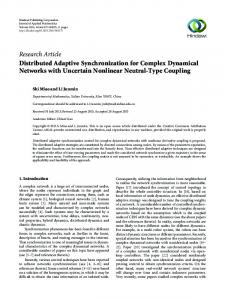
1. Introduction The beam string structure (BSS) is a type of prestressed system initially presented by Saitoh in the early 1980s [1, 2]. It has good mechanical behavior and now has been widely used in large span structures such as airport, exhibition hall, and gym. Three most typical cases that are frequently cited in China are Shanghai Pudong International Airport Terminal, Guangzhou International Convention and Exhibition Center, and the Main Stadium of Harbin International Convention and Exhibition Center. Their span reaches 82.6 m, 126.6 m, and 128.5 m, respectively. The BSS commonly consists of three parts, namely, the upper beam (or a truss), the lower cable, and the vertical link strut, as shown in Figure 1. The prestress in the cable balances the horizontal thrust on the support and decreases the bending moment value on the upper beam, which greatly improves the structural stiffness and capability of the BSS. Despite its relatively light internal force, the vertical link strut still plays an important role in the entire system. Tiny changes on the length of struts will cause wide force redistribution in the entire BSS. Therefore, if the vertical link strut is converted into a kind of adjustable component,
the traditional BSS would become a new kind of smart structure with self-adjustment ability and better mechanical behavior. In recent years, smart structures have become a hot spot of research, which represents the future direction of structure development. A smart civil structure is a civil structure (e.g., buildings, bridges, dams, etc.) that can monitor and react to environmental conditions and the structure’s own conditions, in a predesigned and beneficial manner [3]. Currently, in civil engineering, most research works on smart structures focus on vibration control and have made tremendous achievement. Various types of techniques and devices such as magnetorheological (MR) damper, shape memory alloy (SMA) actuator, hybrid active mass damper (AMD), and piezoceramic actuator, concentrically braced frames (CBF) are applied to vibration control [4–12]. Meanwhile, a few studies have paid attention to the smart structure based on the control of static characteristics such as deformation and internal force. Some typical cases involve the applications of smart prestress, smart strut, and smart beam [13, 14]. This paper illustrates a typical kind of smart structure based on static characteristics control, namely, the adaptive
Mathematical Problems in Engineering Beam BSS
Cable
Strut
2 S
C1
Sensor
Adaptive BSS
A1
A2 C2
···
A n−1 Cn
An Cn+1
··· its m element un Actuator
Figure 2: Model of an adaptive BSS. Figure 1: Diagram of an adaptive BSS.
BSS. The adaptive BSS can optimize the working status itself by controlling the length of one or several adjustable link struts according to the changes of external loads, as shown in Figure 1. The control device commonly consists of actuators in each strut and sensors on the beam. Following a typical smart structure style, the working principle is as follows. Due to the excitation of external loads, the static characteristics of the structure have made changes. The sensors placed on the structure monitor that change and transfer data to the controller. Via analysis and calculation, an adjustment strategy is generated by the controller and sent to actuators. The actuators then execute the adjustment strategy, and a complete control process ends. The key point of the control process is to determine the length adjustment values of actuators according to the displacement values obtained by sensors. The adaptive BSS is a novel smart structure, so there are rarely systemic research works to be referenced. Some similar researches on smart beams have been reported, but those beams cannot be considered as a true BSS system and usually contain one or two struts. Basically, the static control of those kinds of smart beams includes internal force control and displacement control. Noack et al. studied the control strategy of a smart beam with one active strut under moving loads, taking the displacement as the control objective [13]. Sobek and Teuffel carried on similar work and updated the system to beams with two active struts [14]. For the smart beam with one or two active struts, heuristic selection and exhaustive method could meet the requirement of static control analysis, while for a typical adaptive BSS with a set of struts, the entire search space becomes too large and the brute methods can no longer satisfy the requirement. For large solution spaces searching problems, stochastic search techniques such as genetic algorithm (GA) and simulated annealing (SA) algorithm are usually applied. On the other hand, all works mentioned above assume that the smart prestressed system works in linearity; therefore, the linear static control method is employed. However, the BSS system usually contains a set of struts and cables which make the structure flexible to a certain degree. For a flexible structure with large displacement behavior, nonlinear method is commonly incorporated into control algorithm for better accuracy. Similar nonlinear static control method had been used in cable-strut structures in the past [15]. Although the static control optimization model for cable-strut structures is not suitable for the adaptive BSS,
its nonlinear static control method could still be a good reference. In this paper, a static control algorithm for adaptive BSS has been presented for the adjustment solution. It is based on nonlinear finite element method and SA algorithm. The paper is organized as follows. Section 2 establishes an optimization model of adaptive BSS with multiple active struts, and a sensitivity analysis method is applied. Section 3 presents a linear displacement control process mainly by means of an SA algorithm and then proposes a nonlinear iteration to calibrate the result of the linear calculation. Section 4 carries out an example of a three-strut adaptive BSS under different external loads and conducts the comparisons between results from noncontrolled BSS and adaptive BSS. Finally, a summary of the research work is given in Section 5.
2. The Static Control Model Based on Minimal Displacement The mechanical model of adaptive BSS with multiple active struts is established for static control analysis at first, and a sensitivity analysis method is used to evaluate the influence of each of the multiple adjustable struts. The sensitivity analysis method was proposed early in 1980s by SobieszczanskiSobieski et al. to study the sensitivity of optimum solution of problem parameters. The basic principle of sensitivity analysis is to get the derivative of the optimum solution to multiple variables and then obtain the optimum solution and the corresponding variables via calculating the weight factors of different variables [16]. Besides, a working status factor of the BSS system based on displacement is defined as the control objective. 2.1. Mechanical Modeling of Adaptive BSS. The simplified mechanical model of a typical adaptive BSS with multiple active struts is shown in Figure 2. The upper beam is subdivided into plenty of small beam element units for more accuracy. Each active strut is considered as a single link element, and the cable segment between two joints is treated as a single cable element unit. Some assumptions are given when performing static control analysis: (1) the material nonlinearity of the adaptive BSS is not considered; (2) the fixed hinge bearing is on the left end of the beam and the sliding hinge bearing is on the right; (3) the weight of the structure is converted into equivalent dead loads, and all external loads
Mathematical Problems in Engineering
3
are applied on the beam only; and (4) the joint connecting the cable and the strut is a hinge, and the cable between two joints is considered as a straight line with tension only, ignoring the effect of the cable sag. The BSS is assumed to adopt linear behavior, and according to superposition principle, the internal force and displacement value of the structure after adjustment are F𝐶 = F0 + ΔF,
(1)
d𝐶 = d0 + Δd,
𝑓𝐷𝑗
where F0 and d0 represent the internal force and displacement value of the structure before adjustment, respectively. After an arbitrary adjustment, the structure has new internal force of F𝐶 and displacement of d𝐶. ΔF and Δd are the increments of the internal force and displacement, respectively, which are given by ΔF = S𝐴,𝐹 e𝐴,
(2)
Δd = S𝐴,𝐷e𝐴,
where S𝐴,𝐹 and S𝐴,𝐷 are the sensitivity matrix of internal force and displacement, respectively. e𝐴 denotes the length adjustment values of active struts. For a specific BSS with elements amounted to 𝑁𝑒 , nodes amounted to 𝑁𝑛 , and adjustable struts amounted to 𝑁𝑎 , (2) can be expressed as ΔF1
ΔF11
𝑁
ΔF21 ⋅ ⋅ ⋅ ⋅ ⋅ ⋅ ΔF1 𝑎
] 𝑒𝐴1 [ ] [ ] [ 𝑁𝑎 ] [ 1 2 ] [ ΔF2 ] [ ΔF ΔF ⋅ ⋅ ⋅ ⋅ ⋅ ⋅ ΔF ] [ 𝑒𝐴2 ] [ 2 2 2 [ ]=[ ], ] [ [⋅ ⋅ ⋅ ⋅ ⋅ ⋅ ] [ [⋅ ⋅ ⋅ ⋅ ⋅ ⋅] [ ] [⋅ ⋅ ⋅ ⋅ ⋅ ⋅ ⋅ ⋅ ⋅ ⋅ ⋅ ⋅ ΔF𝑗 ⋅ ⋅ ⋅ ⋅ ⋅ ⋅] ] 𝑖 ] 𝑒 [ [ 𝐴𝑁𝑎 ] 𝑁 1 2 [ ΔF𝑁𝑒 ] ΔF𝑁𝑒 ΔF𝑁𝑒 ⋅ ⋅ ⋅ ⋅ ⋅ ⋅ ΔF𝑁𝑎𝑒 ] [ Δd1
Δd11
values of internal force and displacement of the beam. Technically, the function of the prestressed cable and link struts is to improve the capability of the beam, and the mechanical behavior of the beam reflects the performance of the entire BSS system. In this paper, a displacement state factor 𝑓𝐷𝑗 of the beam is specified with (5) to identify the performance of the system:
(3)
𝑁
Δd21 ⋅ ⋅ ⋅ ⋅ ⋅ ⋅ Δd1 𝑎
] 𝑒𝐴1 [ ] ] [ [ 𝑁 1 2 ] [ [ [ Δd2 ] [ Δd2 Δd2 ⋅ ⋅ ⋅ ⋅ ⋅ ⋅ Δd2 𝑎 ] ] [ 𝑒𝐴2 ] ]=[ [ ], ] [ [⋅ ⋅ ⋅ ⋅ ⋅ ⋅ ] [ [⋅ ⋅ ⋅ ⋅ ⋅ ⋅] ] [⋅ ⋅ ⋅ ⋅ ⋅ ⋅ ⋅ ⋅ ⋅ ⋅ ⋅ ⋅ Δd𝑗 ⋅ ⋅ ⋅ ⋅ ⋅ ⋅] [ ] 𝑖 ] 𝑒 [ [ 𝐴𝑁𝑎 ] 𝑁 1 2 [ Δd𝑁𝑛 ] Δd𝑁𝑛 Δd𝑁𝑛 ⋅ ⋅ ⋅ ⋅ ⋅ ⋅ Δd𝑁𝑎𝑛 ] [
(4)
𝑗 Δd𝑖
denotes the displacement increment of node 𝑗 where when the adjustable strut 𝑖 changes a unit value, and it is 𝑗,𝑥 𝑗,𝑦 𝑗,𝑧 𝑗 described as [Δd𝑖 , Δd𝑖 , Δd𝑖 ]𝑇 . ΔF𝑖 indicates the internal force increment of element 𝑗 when the adjustable strut 𝑖 𝑗,𝐿 𝑗,𝐿 changes a unit value, and it is described as [Δ𝑁𝑖 , Δ𝑆𝑖 , 𝑗,𝐿 𝑗,𝑅 𝑗,𝑅 𝑗,𝑅 𝑗,𝐿 Δ𝑀𝑖 , Δ𝑁𝑖 , Δ𝑆𝑖 , Δ𝑀𝑖 ]𝑇 for beam element and [Δ𝑁𝑖 , 𝑗,𝑅 𝑇 Δ𝑁𝑖 ] for cable and link elements. 2.2. The Minimal Displacement Control Objective. The BSS is a self-balancing system with a set of link struts connecting the beam and the cable. The beam withstands external loads directly and bears bending moment and pressure. The prestress applied in the cable largely decreases the maximum
𝑑𝐵𝑗 { { , 𝑑𝐵𝑗 ≥ 0, { { { 𝑑𝐵𝑈 ={ { { 𝑑𝐵𝑗 { { , 𝑑𝐵𝑗 < 0, 𝐿 { 𝑑𝐵
(5)
in which 𝑑𝐵𝑈 and 𝑑𝐵𝐿 refer to the upper bound and lower bound of the adjustable displacement range of node 𝑗 on the beam, respectively. Normally the length of 1/250 span of the structure is considered as the allowable value according to design code. 𝑑𝐵𝑗 is the displacement value of node 𝑗. A working status factor 𝛽𝐷 of the BSS system based on displacement is given by 𝛽𝐷 = max (𝑓𝐷𝑗 ) ,
𝑗 = 1, 2, . . . , 𝑛 + 1,
(6)
where 𝑛 is the amount of subdivisions of the beam. The optimum design for a traditional BSS is to search the structural shape, component cross-section size, and cable prestress to satisfy the requirement of 𝛽𝐷 ≤ 1 under the most unfavorable load. For an adaptive BSS, the basic principle of displacement control is to improve the internal force distribution and decrease the maximal value of displacement via adjusting the length of the active struts. When 𝛽𝐷 reaches the minimum, the working status of the BSS is probably the best. In addition, during the control process, some other conditions such as the structural material strength and the adjustment range of the active struts should be satisfied at the same time. All constraint conditions are detailed as 𝑑𝐵𝐿 ≤ 𝑑𝐵𝑗 ≤ 𝑑𝐵𝑈,
(7)
𝜎𝐵𝐶 ≤ 𝜎𝐵𝑗 ≤ 𝜎𝐵𝑇 ,
(8)
𝜎𝐴𝐶 ≤ 𝜎𝐴𝑗 ≤ 0,
(9)
𝑁𝐶𝐿 ≤ 𝑁𝐶𝑗 ≤ 𝑁𝐶𝑇 ,
(10)
𝐿 𝑈 ≤ 𝑒𝐴𝑗 ≤ 𝑒𝐴 , 𝑒𝐴
(11)
where 𝜎𝐵𝐶 and 𝜎𝐵𝑇 are the allowable compressive and tensional stress values of the beam, respectively. 𝜎𝐴𝐶 is the allowable compressive stress value of the active strut. 𝑁𝐶𝑇 denotes the allowable tensional force value of cables, and 𝑁𝐶𝐿 is the lower bound of tensional force range that usually equals 5% of 𝑁𝐶𝑇 . 𝐿 𝑈 𝑒𝐴 and 𝑒𝐴 stand for the lower bound and upper bound of the adjustment length range of the active strut. 𝑑𝐵𝑗 , 𝜎𝐵𝑗 , 𝜎𝐴𝑗 , 𝑁𝐶𝑗 , and 𝑒𝐴𝑗 denote the displacement value of node 𝑗 of the beam, the stress value of element unit 𝑗 of the beam, the stress value of active struts 𝑗, the tensional force of cable 𝑗, and the length
4
Mathematical Problems in Engineering
adjustment value of active strut 𝑗, respectively. Detailed stress expressions of different structural components are specified as 𝑀𝐵𝑗,𝐿 𝑀𝐵𝑗,𝑅 𝑁𝐵𝑗,𝐿 ± max ( 𝜎𝐵𝑗 = , ) , 𝑊𝐵𝑗 𝑊𝐵𝑗 𝐴 𝐵𝑗 (12) 𝑁𝐴𝑗,𝐿 𝜎𝐴𝑗 = , 𝐴 𝐴𝑗 where 𝑁𝐵𝑗,𝐿 , 𝑀𝐵𝑗,𝐿 , and 𝑀𝐵𝑗,𝑅 are the axial force, moment on left end and moment on right end of the unit 𝑗 of the beam, respectively. 𝐴 𝐵𝑗 and 𝑊𝐵𝑗 are the cross-section area and inertia modulus of the unit 𝑗 of the beam, respectively. 𝑁𝐴𝑗,𝐿 and 𝐴 𝐴𝑗 are the axial force and cross-section area of the active strut 𝑗. In summary, the static control analysis based on minimal displacement to adaptive BSS is treated as an optimization problem, with 𝛽𝐷 as the cost function and (7) to (11) as constraints, which is indicated in solve
(𝑘−1) + 𝛿F(𝑘) , F(𝑘) 𝐶 = F𝐶 (𝑘−1) + 𝛿d(𝑘) , d(𝑘) 𝐶 = d0
𝛽𝐷
(13)
(7) to (11) .
3. The Static Control Algorithm 3.1. Linear Displacement Control Process Using SA. Linear displacement control (LDC) is a basis of nonlinear displacement control (NDC). In this paper, SA algorithm is employed to search an optimal adjustment solution. It is a stochastic search method that has been successfully applied to a variety of problems in optimization research. In its application to this paper, the entire calculation process starts with randomly generating a set of 𝑒𝐴 that satisfy (11) and evaluating the working status factor 𝛽𝐷 and all static results of this selection. And then a new selection of 𝑒𝐴 is generated by a random alteration within a neighborhood of last selection. The 𝛽𝐷 of the new selection is calculated and compared with the minimum 𝛽𝐷 of all the previous selections. If the current 𝛽𝐷 is lower than the minimum 𝛽𝐷, the new selection takes over directly. Otherwise, a Metropolis algorithm is used to determine whether the new selection of 𝑒𝐴 is accepted or not. And for every Mapkob length of repetitions of the above procedure, a cooling operation is performed once. It will not stop until the optimized value to the minimum 𝛽𝐷 is lower than the given criterion 𝜀 or the system is cooled over. The flowchart of the entire process described above is summarized in Figure 3. 3.2. Nonlinear Displacement Control Procedures. The linear displacement control algorithm presented in the previous section is no longer suitable when considering the structural nonlinearity of the BSS system. Referring to the nonlinear finite element method and based on the LDC algorithm, the NDC algorithm is established via applying an iterative procedure analogous to the Newton-Raphson method, as shown in Figure 4. Firstly, an approximate solution has been obtained by using the LDC algorithm, as shown by AB in Figure 4.
(14)
(𝑘) where F(𝑘) 𝐶 and d𝐶 are the estimated solution of the internal and force and displacement on 𝑘 step, respectively. F(𝑘−1) 𝐶 d(𝑘−1) are the real state of the internal force and displacement 𝐶 on 𝑘 − 1 step. 𝛿F(𝑘) and 𝛿d(𝑘) are calculated according to 𝛿𝑒(𝑘) which is generated by LDC with 𝛽𝐷,min (𝑘) as the target. Accordingly, at each iteration step, the deviation of the working status factor from the real state is defined as
𝑒𝐴
make 𝛽𝐷 (𝑒𝐴 ) → min s.t.
And then the structural response from the linear solution is revised to its real state C by nonlinear finite element method (NFEM). The above process can be repeated at any new state (e.g., C) until the structure converges to the target state. For NDC algorithm, (1) is no longer valid and should be replaced by the iterative equations as
(𝑘)
= 𝛽𝐷,min (𝑘) − 𝛽𝐷(𝑘) ,
(15)
(𝑘)
means the deviation of the working status factor where 𝛽𝐷 on 𝑘 step, 𝛽𝐷,min (𝑘) is the minimal working status factor generated by LDC on 𝑘 step, and 𝛽𝐷(𝑘) denotes the working status factor of real state after revision by NFEM. Accordingly, the deviation of the internal force and displacement from the real (𝑘) (𝑘) state can also be expressed by 𝐹𝐶 and 𝑑𝐶 , respectively. By introducing a Newton-Raphson iterative procedure to (14), they can converge to the optimal state of the structure finally. The flowchart of the solution searching process of NDC algorithm is shown in Figure 5. A Matlab program has been written to implement the algorithm and has been used for the example in the next section.
4. Example As shown in Figure 6, a three-strut adaptive BSS with a span of 48 meters and an inverted rise of 6 meters is considered as an example for the control algorithm verification. The straight beam (thick line) employs a square cross section steel tube, and the size of the cross section is 300 mm in width, 400 mm in height, and 20 mm in wall thickness. The beam is subdivided into 120 small beam element units for more accurate calculation. The three active link struts (middle thick line) are circular pipes with a diameter of 140 mm and a wall thickness of 6 mm. The cable (light line) consists of 61 steel wires with a diameter of 5 mm, and the prestress in the cable is produced by the dead load. In calculation, all constraint conditions are detailed as shown in Table 1. The elasticity modulus of the beam and struts is 2.06 × 10⁵ N/mm2 , and that of the cable is 1.95 × 10⁵ N/mm2 . For a roof structure, there are usually four types of external loads being considered, namely, the dead load, the full span live load, the half span live load, and the upward wind load. They are notated as 𝑆𝐺, 𝑆𝑄1 , 𝑆𝑄2 , and 𝑆𝑊, respectively. Assume that all loads are applied on the beam, and 𝑆𝐺 = 5 kN/m. Three typical load cases are calculated for the next
Mathematical Problems in Engineering
5
Start
Calculating internal force sensitivity SA,F and displacement sensitivity SA,D using nonlinear finite element method
Calculating FC and dC by Eq. (1)
Randomly generate initial eA from Eq. (11)
Calculating 𝜎Bj and 𝜎Aj by Eq. (12)
Calculating FC and dC by Eq. (1)
Is the range of the values of dC , 𝜎Bj , 𝜎Aj , and NCj satisfied according to the Eq. (7) to (11)?
Calculating 𝜎Bj and 𝜎Aj by Eq. (12)
No
Randomly generate a new eA in neighborhood of last No accepted selection and apply cooling operation for every Mapkob length of iterations
Yes
Is the range of the values of dC , 𝜎Bj ,
Yes
𝜎Aj , and NCj satisfied according to the
Calculating control objective function 𝛽D by Eq. (4)
Eq. (7) to (11)? No
Current 𝛽D < old 𝛽D ? Yes
Metropolis algorithm
Accept current selection of eA
|𝛽D − 𝛽D,min | = 𝜀 or cooling schedule completed?
No
Yes Output optimized results End
Figure 3: SA process for LDC solution.
(1) eA
(0) A 𝛽D
(1) 𝛽D
(2) (3) eA eA
eA
C (1) 𝛽D
LDC (1) 𝛽D,min
B NFEM
𝛽D
Figure 4: Illustration of iterations in searching for solution of NDC.
discussion. Load Case 1, 𝑆𝐺 + 𝑆𝑄1 , is the most unfavorable downward load case with uniform distribution. Load Case 2, 𝑆𝐺 + 𝑆𝑄2 , is the most unfavorable downward load case with unsymmetrical distribution. Load Case 3, 𝑆𝐺 +𝑆𝑊, is the most unfavorable upward load case with uniform distribution. In this section, the ultimate loads of 𝑆𝑄1 , 𝑆𝑄2 , and 𝑆𝑊 under the three load cases above are calculated in the case of noncontrolled and controlled structure, respectively. And all the static state results of noncontrol, LDC, and NDC are discussed in details to validate the algorithm and prove the capability of the adaptive system. 4.1. Load Case 1: 𝑆𝐺 + 𝑆𝑄1 . The ultimate load of 𝑆𝑄1 for noncontrolled BSS is calculated as 𝑆𝑄1 = 5.2 kN/m, which is subject to all constraint conditions in Table 1. With the value of 𝑆𝑄1 obtained, calculation under load Case 1, 𝑆𝐺 (5 kN/m) + 𝑆𝑄1 (5.2 kN/m), for noncontrol, LDC, and NDC is then
6
Mathematical Problems in Engineering Table 1: Constraint conditions for calculation.
Allowable displacement of the beam (mm) 𝑑𝐵𝐿 −192
Allowable stress of struts (N/mm2 )
𝑑𝐵𝑈 192
Allowable adjustment of struts (mm)
𝜎𝐴𝐶 −215
𝑒𝐴𝐿 −400
Allowable tension of cables (kN)
𝑒𝐴𝑈 400
𝑁𝐶𝐿 98
Allowable stress of the beam (N/mm2 ) 𝜎𝐵𝑇 𝜎𝐵𝐶 215 −215
𝑁𝐶𝑇 1880
SG
Start
SQ1 Evaluate structural response by nonlinear finite element method, obtain F(0) C and dC (0) , and calculate the structural control objective 𝛽D (0)
SQ2 SW
Initialization: k = 0, 𝛽D (k) = 𝛽D (0) , (k) eA
= 0, and dC
(k)
= dC
A1
C1
(0)
12 m
k = k + 1, generate 𝛿eA (k) by LDC with
C2
A2
12 m
6m
30 × 4 beam element units: B1 , B2 , . . . , B120
C3
A3
12 m
C4 12 m
Figure 6: A three-strut adaptive BSS.
𝛽D,min (k) as target, and calculate 𝛿 dC(k)
200
dC(k) = dC(k−1) + 𝛿 dC(k) , eA (k) = eA (k−1) + 𝛿eA (k) , and update structure configuration with 𝛿 dC(k) and 𝛿eA (k)
100 50 db (mm)
Reevaluate structural response by nonlinear finite element method and obtain FC (k) and dC (k)
150
0 0
10
20
−50 FC (k) = FC (k) + FC (k) , dC(k) = dC(k) + dC (k) , and
update structure configuration with dC (k) and
−100
calculate 𝛽D (k) with dC (k)
−150
30
40
50
L (m)
−200 |𝛽D
(k)
− 𝛽D,min
(k)
| < 𝜀?
No
Yes Output optimized results: (k) (k) eA , dC , and FC (k)
Noncontrol results LDC results NDC results
Figure 7: Displacement state of the beam under load Case 1.
End
Figure 5: Procedures of solution searching for NDC.
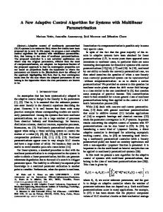
followed, and all the static state results are shown in Table 2. It turns out that the ultimate load of 𝑆𝑄1 is literally subject to the allowable displacement of the beam; that is, 𝛽𝐷 is close to 1. And the adjustment effect of NDC is slightly better than LDC according to 𝛽𝐷. For the main bearing component, namely, the beam, the displacement and moment state directly reflect its working state, as shown in Figures 7 and 8, where the abscissa axis represents the location on the beam. After control, the displacement state improvement is obvious to see and the
moment values become well distributed around the abscissa axis. For further comparison, the ultimate load of 𝑆𝑄1 for the adaptive BSS is calculated as 𝑆𝑄1 = 28.0 kN/m, which is also subject to all constraint conditions. That is to say, after the NDC, the ultimate load level of the structure has increased up to 438 percent. With calculation done under load Case 1: 𝑆𝐺 (5 kN/m) + 𝑆𝑄1 (28.0 kN/m) and all constraint conditions for the noncontrolled structure released, the static state results of noncontrol and NDC are shown in Table 3. It is clear that the ultimate load of 𝑆𝑄1 is subject to the allowable stress of the beam; that is, |𝜎𝐵 |max is close to 215 N/mm2 ; meanwhile, the adjustments of strut 1 and strut 3 all reach the upper bound.
Mathematical Problems in Engineering
7
Table 2: Static state results under load Case 1 with 𝑆𝑄1 = 5.2 kN/m. Working Compressive stress status factors values of struts (N/mm2 ) 𝛽𝐷 0.992↑ 0.085 0.035
Notations Noncontrol results LDC results NDC results
𝜎𝐴1 −51.23 −59.18 −59.31
𝜎𝐴2 −50.76 −39.71 −39.52
𝜎𝐴3 −51.23 −59.18 −59.31
Minimal and maximum tension values of cables (kN)
Adjustment values of struts (mm) 𝑒𝐴1 0.00 261.60 253.80
𝑒𝐴2 0.00 −47.70 −66.00
𝑒𝐴3 0.00 261.70 253.50
𝑁𝐶,min 503.60 506.77 506.84
𝑁𝐶,max 535.10 540.58 540.63
Maximum stress values of the beam (N/mm2 ) |𝜎𝐵 |max 77.15 87.16 85.90
Table 3: Static state results under load Case 1 with 𝑆𝑄1 = 28.0 kN/m. Working status factor 𝛽𝐷 4.247 0.516
Notations Noncontrol results NDC results
Compressive stress of struts (N/mm2 )
Adjustment value of struts (mm)
𝜎𝐴1 𝜎𝐴2 𝜎𝐴3 𝑒𝐴1 𝑒𝐴2 𝑒𝐴3 −180.25 −174.15 −180.25 0.00 0.00 0.00 −178.55 −151.45 −178.55 399.90 ↑ 385.70 399.90 ↑
250
200
200
150
150
𝑁𝐶,max 1750.32 1666.44
|𝜎𝐵 |max 486.89 214.99↑
50
50 0 10
20
30
40
50
L (m)
−100
db (mm)
Mb (kN·m)
𝑁𝐶,min 1637.07 1557.37
Maximum stress of beam (N/mm2 )
100
100
−50 0
Minimal and maximum tension of cables (kN)
0 0
10
20
−50
30
40
50
L (m)
−100
−150 −200
−150
−250
−200
Noncontrol results LDC results NDC results
Noncontrol results LDC results NDC results
Figure 8: Moment state of the beam under load Case 1.
Figure 9: Displacement state of the beam under load Case 2.
The noncontrol results show that the displacement and stress values of the beam all largely exceed the limitation.
For the adaptive BSS, the ultimate load of 𝑆𝑄2 is calculated as 𝑆𝑄2 = 15.3 kN/m. It increases up to 256 percent after the NDC, which may be limited by the adjustment bound of the struts. Another round of calculation is conducted under load Case 2: 𝑆𝐺 (5 kN/m) + 𝑆𝑄2 (15.3 kN/m), and all constraint conditions for the non-controlled structure are released. Results shown in Table 5 reveal that the ultimate load of 𝑆𝑄2 is still subject to the allowable displacement of the beam; meanwhile, the adjustments of strut 1 and strut 2 have reached the upper bound. The noncontrol results show that the displacement and stress values of the beam have largely exceeded the limitation as well.
4.2. Load Case 2: 𝑆𝐺 + 𝑆𝑄2 . Similarly, the ultimate load of 𝑆𝑄2 for noncontrolled BSS is calculated as 𝑆𝑄2 = 4.3 kN/m. Table 4 shows all the static state results of noncontrol, LDC, and NDC under load Case 2: 𝑆𝐺 (5 kN/m) + 𝑆𝑄2 (4.3 kN/m). Apparently, the ultimate load of 𝑆𝑄2 is still subject to the allowable displacement of the beam, and the adjustment effect of NDC is somewhat more significant than LDC. The adjustments of strut 1 and strut 3 reach the upper bound, and lower bound respectively, which indicates that wider adjustment range is required for unsymmetrically distributed loads. The displacement and moment distributions of the beam are shown in Figures 9 and 10, respectively. After control, the displacement and moment states turn to be well distributed, and the negative influence of the unsymmetrical loads has decreased substantially.
4.3. Load Case 3: 𝑆𝐺 +𝑆𝑊. The ultimate upward load of 𝑆𝑊 for noncontrolled BSS is calculated as 𝑆𝑊 = −3.0 kN/m. Table 6 presents calculation results under load Case 3: 𝑆𝐺 (5 kN/m) + 𝑆𝑊 (−3.0 kN/m). It turns out that the ultimate upward load of 𝑆𝑊 is subject to the allowable minimal tension of the cable.
8
Mathematical Problems in Engineering Table 4: Static state results under load Case 2 with 𝑆𝑄2 = 4.3 kN/m. Working Compressive stress status factors values of struts (N/mm2 ) 𝛽𝐷 0.999↑ 0.353 0.148
Notations Noncontrol results LDC results NDC results
𝜎𝐴1 −37.40 −41.93 −42.87
𝜎𝐴2 −35.32 −41.99 −40.41
Minimal and maximum tension values of cables (kN)
Adjustment values of struts (mm)
𝜎𝐴3 𝑒𝐴1 −33.68 0.00 21.58 399.90↑ −22.53 399.40↑
𝑒𝐴2 𝑒𝐴3 0.00 0.00 311.60 −394.10↑ 233.10 −398.70↑
𝑁𝐶,min 352.66 359.53 358.39
𝑁𝐶,max 375.00 383.38 382.39
Maximum stress values of the beam (N/mm2 ) |𝜎𝐵 |max 96.48 80.29 68.75
Table 5: Static state results under load Case 2 with 𝑆𝑄2 = 15.3 kN/m. Working Compressive stress status factors values of struts (N/mm2 ) 𝛽𝐷 3.513 0.991↑
Notations Noncontrol results NDC results
𝜎𝐴1 −76.02 −79.05
𝜎𝐴2 −63.63 −75.39
𝜎𝐴3 𝑒𝐴1 𝑒𝐴2 𝑒𝐴3 −52.13 0.00 0.00 0.00 −31.05 399.90 ↑ 399.90 ↑ −354.90
250
200
200
150
150
𝑁𝐶,max 665.73 669.20
|𝜎𝐵 |max 476.22 202.83
50
50 0 10
20
30
40
50
L (m)
−100
db (mm)
Mb (kN·m)
𝑁𝐶,min 623.13 625.84
Maximum stress values of the beam (N/mm2 )
100
100
−50 0
Minimal and maximum tension values of cables (kN)
Adjustment values of struts (mm)
0 0
10
20
−50
30
40
50
L (m)
−100
−150 −200
−150
−250
−200
Noncontrol results LDC results NDC results
Figure 10: Moment state of the beam under load Case 2.
All the static state results are small and close, which means the effect of adjustment is not that obvious. As shown in Figures 11 and 12, the improvements of the displacement and moment states after control are slight. Finally, the ultimate load of 𝑆𝑊 for the adaptive BSS is calculated as 𝑆𝑊 = −3.3 kN/m which increases only 10 percent. Calculation under load Case 3: 𝑆𝐺 (5 kN/m) + 𝑆𝑊 (−3.3 kN/m) is done with all constraint conditions for the noncontrolled structure released. The static state results of noncontrol and NDC are shown in Table 7. Obviously, the ultimate load of 𝑆𝑊 is still subject to the allowable minimal tension of the cable; meanwhile, the adjustments of strut 2 reach the lower bound. The noncontrol results indicate that the minimal tension value of the cable has exceeded the limitation significantly.
Noncontrol results LDC results NDC results
Figure 11: Displacement state of the beam under load Case 3.
5. Conclusions The adaptive BSS is a typical smart structure that can optimize its own working status by controlling the length of several active struts. The core issue here is to determine the length adjustment values of the active struts according to the working status of the structure. In this paper, an optimization model of adaptive BSS with multiple active struts is established at first. It is based on a sensitivity analysis method and takes displacement as control objective. Then, on the basis of an SA algorithm, an LDC process has been proposed to calculate the adjustment. An iteration procedure consisting of the LDC process and a nonlinear iteration is constructed afterwards to achieve the displacement control of structures with nonlinear behaviour. In the final section, an example of a three-strut active BSS under different external loads has been
Mathematical Problems in Engineering
9
Table 6: Static state results under load Case 3 with 𝑆𝑊 = −3.0 kN/m. Working Compressive stress status factors values of struts (N/mm2 ) 𝛽𝐷 0.194 0.084 0.007
Notations Noncontrol results LDC results NDC results
𝜎𝐴1 −9.74 −11.74 −11.52
𝜎𝐴2 −9.72 −7.83 −7.89
𝜎𝐴3 −9.74 −11.79 −11.51
Adjustment values of struts (mm) 𝑒𝐴1 0.00 141.20 125.90
𝑒𝐴2 𝑒𝐴3 0.00 0.00 −191.40 147.90 −190.60 125.60
Minimal and maximum tension values of cables (kN) 𝑁𝐶,min 94.56↑ 103.08 101.81
𝑁𝐶,max 104.50 109.73 108.35
Maximum stress values of the beam (N/mm2 ) |𝜎𝐵 |max 14.71 19.25 16.42
Table 7: Static state results under load Case 3 with 𝑆𝑊 = −3.3 kN/m. Working Compressive stress status factors values of struts (N/mm2 ) 𝛽𝐷 0.164 0.428
Notations Noncontrol results NDC results
𝜎𝐴1 −8.27 −12.06
𝜎𝐴2 −8.26 −5.02
𝜎𝐴3 −8.27 −12.02
Adjustment values of struts (mm) 𝑒𝐴1 𝑒𝐴2 𝑒𝐴3 0.00 0.00 0.00 269.90 −399.90↑ 261.60
200
𝑁𝐶,max 88.82 100.29
|𝜎𝐵 |max 12.49 30.85
(3) The upward loads make the cable slack, and the capability of the structure is mainly subject to the allowable minimal tension of the cable. The adjustment effect of the active struts to the upward loads is not obvious.
150 100 Mb (kN·m)
𝑁𝐶,min 83.77 93.97↑
Maximum stress values of the beam (N/mm2 )
Obviously, the displacement and moment states of the beam become well distributed after control.
250
50 0 −50 0
Minimal and maximum tension values of cables (kN)
10
20
30
40
50
L (m)
−100
Acknowledgments The work described in this paper was financially supported by the National Key Technology R&D Program (2012BAJ07B03), the National Science Foundation of China (Grant no. 51178415), and Qianjiang Scholar Foundation of Zhejiang Province (2013R10038).
−150 −200 −250
Noncontrol results LDC results NDC results
Figure 12: Moment state of the beam under load Case 3.
carried out to verify the feasibility and accuracy of the static control algorithm. With the example study completed, some conclusions are summarized as follows. (1) As a semirigid structure, the BSS has certain nonlinear behaviour. Comparisons between results from the NDC and LDC show that the computationalcontrolled effect of the NDC is somewhat more significant than LDC. (2) When the structure is under downward loads, the working status of the adaptive BSS has been significantly improved after control, and the adaptive BSS has much stronger capability than the noncontrolled one. To unsymmetrical distributed loads, wider adjustment range of the active struts is required.
References [1] M. Saitoh, “Hybrid form-resistance structure,” in Shells, Membranes, and Space Frames: Proceedings of the IASS Symposium on Membrane Structures and Space Frames, Osaka, Japan, Butterworth-Heinemann Limited, 1986. [2] M. Saitoh, A. Okada, K. Maejima, and T. Gohda, “Study on mechanical characteristics of a light-weight complex structure composed of a membrane and a beam string structure,” in Proceedings of the IASS-ASCE International Symposium on Spatial, Lattice and Tension Structures, pp. 632–641, April 1994. [3] Y. Wang and K. H. Law, “Wireless sensor networks in smart structural technologies,” in Recent Advances in Wireless Communications and Networks, J.-C. Lin, Ed., InTech, 2011. [4] Z.-D. Xu, Y.-P. Shen, and Y.-Q. Guo, “Semi-active control of structures incorporated with magnetorheological dampers using neutral networks,” Smart Materials and Structures, vol. 12, no. 1, pp. 80–87, 2003. [5] Z.-D. Xu, “Earthquake mitigation study on viscoelastic dampers for reinforced concrete structures,” Journal of Vibration and Control, vol. 13, no. 1, pp. 29–43, 2007. [6] Z.-D. Xu, Q. Tu, and Y.-F. Guo, “Experimental study on vertical performance of multi-dimensional earthquake isolation and
10
[7]
[8]
[9]
[10]
[11]
[12]
[13]
[14]
[15]
[16]
Mathematical Problems in Engineering mitigation devices for long-span reticulated structures,” Journal of Vibration and Control, vol. 18, no. 13, pp. 1971–1985, 2012. H. Li, H. Qian, and G. Song, “Experimental and analytical investigation on innovative hybrid shape memory alloys dampers for structural control,” in Active and Passive Smart Structures and Integrated Systems 2008, vol. 6928 of Proceedings of SPIE, March 2008. G. Song, B. Kelly, B. N. Agrawal, P. C. Lam, and T. S. Srivatsan, “Application of shape memory alloy wire actuator for precision position control of a composite beam,” Journal of Materials Engineering and Performance, vol. 9, no. 3, pp. 330–333, 2000. L. Li, G. Song, and J. Ou, “Hybrid active mass damper (AMD) vibration suppression of nonlinear high-rise structure using fuzzy logic control algorithm under earthquake excitations,” Structural Control and Health Monitoring, vol. 18, no. 6, pp. 698– 709, 2011. V. Sethi and G. Song, “Multimodal vibration control of a flexible structure using piezoceramic sensor and actuator,” Journal of Intelligent Material Systems and Structures, vol. 19, no. 5, pp. 573– 582, 2008. G. Li and L. A. Fahnestock, “Seismic response of single-degreeof-freedom systems representing low-ductility steel concentrically braced frames with reserve capacity,” Journal of Structural Engineering, vol. 139, no. 2, pp. 199–211, 2013. G. Li, L. A. Fahnestock, and H.-N. Li, “Simulation of steel brace hysteretic response using the force analogy method,” Journal of Structural Engineering, vol. 139, no. 4, pp. 526–536, 2013. T. Noack, J. Ruth, and U. M¨uller, “Adaptive hybrid structures,” in Proceedings of the International Conference on Adaptable Building Structures, Eindhoven, The Netherlands, 2006. W. Sobek and P. Teuffel, “Adaptive systems in architecture and structural engineering,” in Smart Structures and Materials 2001: Smart Systems for Bridges, Structures, and Highways, vol. 4330 of Proceedings of SPIE, pp. 36–45, March 2001. J. Du, H. Bao, D. Yang, Y. Wang, and C. Cui, “Initial equilibrium configuration determination and shape adjustment of cable network structures,” Mechanics Based Design of Structures and Machines, vol. 40, no. 3, pp. 277–291, 2012. J. Sobieszczanski-Sobieski, J.-F. Barthelemy, and K. M. Riley, “Sensitivity of optimum solutions of problem parameters,” AIAA Journal, vol. 20, no. 9, pp. 1291–1299, 1982.
Advances in
Operations Research Hindawi Publishing Corporation http://www.hindawi.com
Volume 2014
Advances in
Decision Sciences Hindawi Publishing Corporation http://www.hindawi.com
Volume 2014
Journal of
Applied Mathematics
Algebra
Hindawi Publishing Corporation http://www.hindawi.com
Hindawi Publishing Corporation http://www.hindawi.com
Volume 2014
Journal of
Probability and Statistics Volume 2014
The Scientific World Journal Hindawi Publishing Corporation http://www.hindawi.com
Hindawi Publishing Corporation http://www.hindawi.com
Volume 2014
International Journal of
Differential Equations Hindawi Publishing Corporation http://www.hindawi.com
Volume 2014
Volume 2014
Submit your manuscripts at http://www.hindawi.com International Journal of
Advances in
Combinatorics Hindawi Publishing Corporation http://www.hindawi.com
Mathematical Physics Hindawi Publishing Corporation http://www.hindawi.com
Volume 2014
Journal of
Complex Analysis Hindawi Publishing Corporation http://www.hindawi.com
Volume 2014
International Journal of Mathematics and Mathematical Sciences
Mathematical Problems in Engineering
Journal of
Mathematics Hindawi Publishing Corporation http://www.hindawi.com
Volume 2014
Hindawi Publishing Corporation http://www.hindawi.com
Volume 2014
Volume 2014
Hindawi Publishing Corporation http://www.hindawi.com
Volume 2014
Discrete Mathematics
Journal of
Volume 2014
Hindawi Publishing Corporation http://www.hindawi.com
Discrete Dynamics in Nature and Society
Journal of
Function Spaces Hindawi Publishing Corporation http://www.hindawi.com
Abstract and Applied Analysis
Volume 2014
Hindawi Publishing Corporation http://www.hindawi.com
Volume 2014
Hindawi Publishing Corporation http://www.hindawi.com
Volume 2014
International Journal of
Journal of
Stochastic Analysis
Optimization
Hindawi Publishing Corporation http://www.hindawi.com
Hindawi Publishing Corporation http://www.hindawi.com
Volume 2014
Volume 2014