This article has been accepted for publication in a future issue of this journal, but has not been fully edited. Content may change prior to final publication. IEEE TRANSACTIONS ON FUZZY SYSTEMS.
1
Adaptive Fuzzy Output Feedback Control of MIMO Nonlinear Systems with Unknown Dead-Zone Inputs Shaocheng Tong, and Yongming Li
Abstract—This paper is concerned with the problem of adaptive fuzzy tracking control for a class of multi-input and multioutput (MIMO) strict-feedback nonlinear systems with both unknown non-symmetric dead-zone inputs and immeasurable states. In this research, fuzzy logic systems are utilized to evaluate the unknown nonlinear functions, and a fuzzy adaptive state observer is established to estimate the unmeasured states. Based on the information of the bounds of the dead-zone slopes as well as treating the time-varying inputs coefficients as a system uncertainty, a new adaptive fuzzy output feedback control approach is developed via the backstepping recursive design technique. It is shown that the proposed control approach can assure that all the signals of the resulting closed-loop system are semi-globally uniformly ultimately bounded (SGUUB). It is also shown that the observer and tracking errors converge to a small neighborhood of the origin by selecting appropriate design parameters. Simulation examples also are provided to illustrate the effectiveness of the proposed approach. Index Terms—Nonlinear MIMO systems, dead-zone inputs, fuzzy logic systems, adaptive backstepping control.
I. I NTRODUCTION
I
N the past decade, many approximation-based adaptive fuzzy or neural backstepping controllers have been developed for uncertain nonlinear strict-feedback systems [1][26]. [1]-[9] developed adaptive fuzzy or neural backstepping control approaches for uncertain single-input and single-output (SISO) nonlinear systems in strict-feedback form, and adaptive fuzzy or neural backstepping control approaches for uncertain SISO nonlinear strict-feedback systems with the time delays were proposed in [10]-[13]. By designing state observers, [14][18] investigated adaptive fuzzy or neural output feedback control for uncertain SISO nonlinear strict-feedback systems with or without time delays. The results from this investigation allows the assumption that the states of the systems are available for measurement in the above-mentioned control approaches to be removed. On the basis of the results obtained through research for uncertain SISO nonlinear strict-feedback systems, [19]-[22] developed adaptive fuzzy or neural control for uncertain multi-input and multi-output (MIMO) nonlinear systems with or without time delays. Furthermore, [23] developed an adaptive fuzzy dynamic surface control scheme S. C. Tong and Y. M. Li are with the Department of Mathematics, Liaoning University of Technology, Jinzhou, Liaoning, 121001 China, e-mail: (
[email protected]; l y m
[email protected]). This work was supported by the National Natural Science Foundation of China (No.61074014), the Outstanding Youth Funds of Liaoning Province (No.2005219001).
for a class of uncertain MIMO nonlinear systems; and [24][26] presented an adaptive fuzzy output feedback controller for some uncertain MIMO nonlinear systems with immeasurable states. The main features of these adaptive approaches are that they can handle nonlinear systems without the requirement of the matching condition, and that there is no need to linearly parameterize the unknown nonlinear functions. It is well known that nonsmooth nonlinear characteristics such as dead zone, backlash, and hysteresis are common in actuators and sensors such as mechanical connections, hydraulic actuators, and electric servomotors. Dead zone is one of the most important nonsmooth nonlinearities in many industrial processes, since it can severely limit system performance. To handle the systems with unknown dead zones, many adaptive control approaches have been developed in recent years, see for example [27]-[34] and the references therein. Adaptive dead zone inverses are proposed in [27]-[30]. While in [27] and [28], adaptive dead-zone inverses are built for linear and nonlinear systems with immeasurable dead-zone outputs. Asymptotical adaptive cancellation of an unknown dead zone is achieved analytically under the condition that the output of a dead zone is measurable in [29] and [30]. By a given matching condition to the reference model, adaptive control with adaptive dead-zone inverse is introduced in [31]. Adaptive state feedback and output feedback controllers using the backstepping technique and smooth inverse function of the dead zone is developed in [32] for a class of interconnected nonlinear systems without satisfying the matching condition. The above-mentioned control approaches all use an inverse dead-zone nonlinearity to minimize the effects of dead-zone. As an alternative, the robust adaptive controllers are developed for a class of nonlinear systems in [33]-[34] by using a new description of a dead zone, without constructing the inverse of the dead zone. However, the above mentioned adaptive control approaches are only suitable for linear systems, or nonlinear systems with nonlinear functions under certain conditions either exactly known or able to be linearized. In order to cope with the problem that nonlinear systems with dead zones and the uncertainties are not linearly parameterized, two stable adaptive fuzzy control algorithms are proposed by [35]- [37] for a class of SISO or MIMO nonlinear systems preceded by unknown backlash-like hysteresis nonlinearities, respectively. The drawbacks of the results in [35]-[37] are that the uncertain nonlinear systems need to satisfy the matching condition and all the states are directly measured, which limits its use in practice. More recently,
Copyright (c) 2011 IEEE. Personal use is permitted. For any other purposes, permission must be obtained from the IEEE by emailing
[email protected].
This article has been accepted for publication in a future issue of this journal, but has not been fully edited. Content may change prior to final publication. IEEE TRANSACTIONS ON FUZZY SYSTEMS.
robust adaptive NN backstepping controllers are proposed in [38]-[40] for SISO and MIMO nonlinear strict-feedback systems with dead-zone and without satisfying the matching condition. The stability of the resulting closed-loop systems is given by using Lyapunov or integral-type Lyapunov functions. The main limitation in [38]-[40] is that the states of the systems are required to be measurable. In addition, an adaptive fuzzy output feedback control scheme has been developed by [41] for a class of SISO nonlinear systems with unknown deadzone and immeasurable states, in which the k-filters are used to estimate the unmeasured states and the inverse method of the dead zone is constructed. However, this control scheme is only suitable for the SISO nonlinear systems, and can not be applied to MIMO nonlinear systems with unknown dead-zone inputs and immeasurable states. Motivated by the aforementioned observations, an adaptive fuzzy backstepping control approach is proposed for a class of uncertain MIMO strict-feeback nonlinear systems with unknown non- symmetric dead-zones and immeasurable states in this study. In the control design, fuzzy logic systems are first utilized to approximate the unknown functions, and then a fuzzy state observer is designed to estimate the immeasurable states. By using the information of the bounds of the deadzone slopes and treating the time-varying input coefficients as a system uncertainty, a new adaptive fuzzy output feedback approach that does not require constructing the inverse of the dead zone is developed via the backstepping recursive design technique. It is demonstrated that the designed controller can guarantee that all of the signals of the resulting closed-loop system are semi-globally uniformly ultimately bounded (SGUUB), and the observer errors and tracking errors converge to a small neighborhood of the origin by selecting appropriate design parameters. The main contributions of this paper are as follows: (i) The control problem of a class of MIMO uncertain nonlinear systems with the unknown dead zones can be solved by the proposed control approach; (ii) The restrictive conditions imposed on the previous literature [35]-[40] that all the states of the controlled nonlinear systems must be available for measurement may be disregarded; and (iii) The entire control system is proven to be SGUUB in the sense of Lyapunov function.
2
where x ¯i,ji = [xi,1 , . . . , xi,ji ]T ∈ 0
−mir bir , vi ≥ bir −mi (t)vi (t), −bil < vi < bir hi (t) = mil bil , vi ≤ −bil
(3) (4)
Considering the literatures [42]-[45], a FLS consists of four parts: the knowledge base, the fuzzifier, the fuzzy inference engine working on fuzzy rules, and the defuzzifier. The knowledge base for FLS is comprised of a collection of fuzzy If-then rules in the following form: Rl : If x1 is F1l and x2 is F2l and . . . and xn is Fnl ,
(5)
then y is Gl , l = 1, 2, . . . , N
From (5), we have ¯ i, hi (t) ≤ h
¯ i = max{mil bil , mir bir } h
(6)
Define αi = max{mil , mir } and αi = min{mil , mir }, then we could obtain mi (t) = 1 + ρi (t) (7) αi where ρi (t) is a some piecewise positive bounded function. Using (4) and (7), we find out that αi −1 (8) ρi (t) ≤ αi We substitute (7) into (3) and get ui = αi (1 + ρi (t))vi (t) + hi (t)
(9)
Besides, system (1) can be rewritten in the following state space form: x˙ i = Ai xi + Ki yi +
mP i −1 ji =1
Bi,ji fi,ji (¯ xi,ji )
+Bi,mi fi,mi (x, u ¯i−1 ) + Bi,mi ui + di yi = CiT xi −ki,1 .. where Ai = . Bi,ji
, Ki = [ki,1 . . . ki,mi ]T , I −ki,mi 0 . . . 0 T T ¯i−1 = = [0 . . . 1 | {z } . . . 0]mi ×1 , Ci = [10 . . . 0]1×mi , u
ji [u1 , . . . , ui−1 ]T
T
and di = [di,1 , . . . , di,mi ] . Then, we substitute (9) into (10) and have x˙ i = Ai xi + Ki yi +
mP i −1 ji =1
[Bi,ji fi,ji (¯ xi,ji )]
+Bi,mi fi,mi (x, u ¯i−1 ) + Bi,mi αi vi (t)
(11)
+Bi,mi [αi ρi (t)vi (t) + hi (t)] + di yi = CiT xi where vector Ki is chosen such that Ai is a strict Hurwitz matrix. Thus, given a Qi = QT i > 0, there exists a Pi = PiT > 0 satisfying AT i Pi + Pi Ai = −2Qi
where x = (x1 , . . . , xn )T and y are the FLS input and output, respectively. Fuzzy sets Fil and Gl are associated with the fuzzy membership functions µFil (xi ) and µGl (y), respectively. N is the number of rules. Through singleton fuzzifier, center average defuzzification and product inference [42,43], the FLS can be written as Qn PN ¯l i=1 µFil (xi ) l=1 y y(x) = PN Qn (14) l=1 [ i=1 µFil (xi )] where y¯l = max µGl (y). y∈R
We can also define the fuzzy basis functions as Qn i=1 µFil (xi ) ϕl = N P Qn ( i=1 µFil (xi ))
(12)
Control objectives: Utilizing fuzzy logic systems, we can use the given reference signals yi,r , the outputs of the system yi ˆ¯i,ji to determine the controller vi and and the state estimates x parameters adaptive laws θi,ji such that all the signals in the resluting closed-loop system are SGUUB, and also guarantee the observer and tracking errors as small as possible.
(15)
l=1
Denoting θ = [¯ y1 , y¯2 , . . . , y¯N ] = [θ¯1 , θ¯2 , . . . , θ¯N ] and ϕ(x) = [ϕ¯1 (x), . . . , ϕ¯N (x)]T , now (14) becomes as T
y(x) = θT ϕ(x)
(10)
(13)
(16)
Lemma 1[42] : Let f (x) be a continuous function defined on a compact set Ω. Then for any constant ε > 0, there exists a fuzzy logic system (16) such that ¯ ¯ (17) sup ¯f (x) − θT ϕ(x)¯ ≤ ε x∈Ω
III. F UZZY S TATE O BSERVER D ESIGN Note that in the system (1), the functions fi,ji (¯ xi,ji ), i = 1, 2, . . . , n; j = 1, 2, . . . , mi are unknown and the state vectors x ¯i,ji are not measured directly, thus a state observer should be established to obtain the estimations of x ¯i,ji . By observing (2), we know that ui is a function of vi , while on the principle of backstepping design, vi is a function of the vector x, therefore, fi,mi (x, u ¯i−1 ) is also a function of the vector x. By Lemma 1, we can assume that the nonlinear function fi,ji (¯ xi,ji ) in (1) can be approximated by the following FLSs: T fˆi,ji (¯ xi,ji |θi,ji ) = θi,j ϕi,ji (¯ xi,ji ) i
(18)
ˆ¯i,ji and x ˆ¯i,mi as the estimations of x Denote x ¯i,ji and x, T ˆ¯i,ji ), ˆ¯i,ji |θi,ji ) = θi,j ϕi,ji (x respectively, then we have fˆi,ji (x i i = 1, 2 . . . , n, ji = 1, 2, . . . , mi . According to [23,24,41,44,45], the optimal parameter vec∗ tors θi,j is defined as i ∗ θi,j = arg i
min
[
sup
θi,ji ∈Ωi,ji (¯ ˆ xi,ji ,x ¯i,ji )∈Ui,ji
|∆fi,ji |]
(19)
Copyright (c) 2011 IEEE. Personal use is permitted. For any other purposes, permission must be obtained from the IEEE by emailing
[email protected].
This article has been accepted for publication in a future issue of this journal, but has not been fully edited. Content may change prior to final publication. IEEE TRANSACTIONS ON FUZZY SYSTEMS.
4
ˆ¯i,ji |θi,ji ) − fi,ji (¯ where ∆fi,ji = fˆi,ji (x xi,ji ); Ωi,ji and Ui,ji ˆ¯i,ji ), respectively. are the compact sets for θi,ji and (¯ xi,ji , x The corresponding minimum approximation error εi,ji is defined as ¯ ∗ ˆ¯i,ji ¯θi,j εi,ji = fi,ji (¯ xi,ji ) − fˆi,ji (x ) (20) i
The time derivative of Vi,0 along the solution of (25) can be calculated as V˙ i,0 = 1 (e˙ T Pi ej + eT Pi e˙ i )
Assumption 3. There exists an unknown constant ε∗i,ji > 0, such that |εi,ji | ≤ ε∗i,ji . The fuzzy state observer is designed as x ˆ˙ i,1 = fˆi,1 (ˆ xi,1 |θi,1 ) + x ˆi,2 + ki,1 (yi − x ˆi,1 ) ˆ¯i,2 |θi,2 ) + x x ˆ˙ i,2 = fˆi,2 (x ˆi,3 + ki,2 (yi − x ˆi,1 ) .. . x ˆ¯i,mi −1 |θi,mi −1 ) + x ˆ˙ i,mi −1 = fˆi,mi −1 (x ˆi,mi (21) +ki,mi −1 (yi − x ˆi,1 ) ˆ¯i,mi |θi,mi ) + ki,mi (yi − x x ˆ˙ i,mi = fˆi,mi (x ˆi,1 ) +vi yˆi = x ˆi,1
+Bi,mi (αi − 1)vi + Bi,mi (αi ρi (t)vi + hi ) +
mi P ji =1
(27)
Bi,ji εi,ji + di }
ji =1
≤ ≤
τi T T 2 ei Pi Pi ei
+
1 2τi
2 τi 2 2 λmax (Pi )kei k
eT i Pi
mi P ji =1
mi P T ˜ θ˜i,k θi,k
k=1
+
1 2τi
(28)
mi P T ˜ θ˜i,k θi,k
k=1
[Bi,ji εi,ji ]
2 τi 2 2 λmax (Pi )kei k
eT i Pi di ≤
+
1 2τi
mi P ji =1
ε∗i,ji
mi τi 2 1 X 2 λmax (Pi )kei k + d¯i,ji 2 2τi j =1
(29)
(30)
i
yˆi = CiT x ˆi
eT i Pi Bi,mi (αi − 1)vi
Let ei = xi − x ˆi be the observer error, and from (11) and (22), the observer-error equation is as below: e˙ i = Ai ei + Bi,mi (αi − 1)vi +Bi,mi [αi ρi (t)vi + hi ] + di + ∆Fi
(23)
where di = [di,1 , . . . , di,mi ]T and ∆Fi = [∆fi,1 , ∆fi,2 , . . . , ∆fi,mi ]T with ∆fi,ji = fi,ji (¯ xi,ji ) − ˆ¯i,ji |θi,ji ). fˆi,ji (x It is noticed that ˆ¯i,ji |θi,ji ) fi,ji (¯ xi,ji ) − fˆi,ji (x ¯ ∗ ˆ¯i,ji ¯θi,j = fi,ji (¯ xi,ji ) − fˆi,ji (x ) i (24) ¯ ∗ ˆ¯i,ji ¯θi,ji ) − fˆi,ji (x ˆ¯i,ji |θi,ji ) +fˆi,ji (x = εi,ji
T ˆ¯i,ji )] [Bi,ji θ˜i,j ϕi,ji (x i
Applying Young’s inequality, Assumptions 1 and 3, and the ˆ¯i,ji )T ϕi,ji (x ˆ¯i,ji ) ≤ 1, for any a positive constant fact ϕi,ji (x τi , we have mi P T ˆ¯i,ji ) eT Bi,ji θ˜i,j ϕi,ji (x i Pi i
mi P ˆ¯i,ji |θi,ji )] x ˆ˙ i = Ai x ˆ i + K i yi + [Bi,ji fˆi,ji (x
+Bi,mi vi
mi P
ji =1
≤ (22)
i
T = −eT i Qi ei + ei Pi {
Then, we rewrite (21) in the following state space form: ji =1
i
2
T ˆ¯i,ji ) ϕi,ji (x + θ˜i,j i
∗ − θi,ji is the parameter error vector. where θ˜i,ji = θi,j i Substituting (24) into (23), we obtain the error system as
e˙ i = Ai ei +
mi P ji =1
T ˆ¯i,ji )] ϕi,ji (x [Bi,ji θ˜i,j i
+Bi,mi (αi − 1)vi + Bi,mi [αi ρi (t)vi +hi ] +
mi P ji =1
(25)
Bi,ji εi,ji + di
For the error system (25), we also consider the following Lyapunov function candidate: Vi,0 =
1 T e Pi ei 2 i
(26)
≤
2 τi 2 2 λmax (Pi )kei k
+
1 2τi (αi
− 1)2 Mi2
(31)
where λmax (Pi ) is the largest eigenvalue of matrix Pi . From (6) and (8), we apply Young’s inequality and Assumption 1 again and get eT i Pi [Bi,mi (αi ρi (t)vi + hi )] 2
≤ τi λ2max (Pi )kei k +
1 2τi (αi
− αi )2 Mi2 +
1 ¯2 2τi hi
(32)
Substituting (28)-(32) into (27), we arrives at mi 1 X 2 T ˜ ˙ Vi,0 ≤ −qi,0 kei k + θ˜i,k θi,k + δi,0 2τi
(33)
k=1
where qi,0 = λmin (Qi ) − 3τi λ2max (Pi ) and δi,0 = mi mi P P 1 1 ∗ ¯2 + + ε d¯i,ji + 2τ1i (αi − αi )2 Mi2 + 2τ1i h i i,j 2τi 2τi i ji =1 1 (α i− 2τi
ji =1
1)2 Mi2 . Remark 2: It can be seen from (33) that the fuzzy state observer (21) can not guarantee the convergence of the observer errors. Therefore, it is necessary to design a controller to keep the resulting closed-loop system stable in the sense of Lyapunov function in next section. IV. F UZZY A DAPTIVE C ONTROL D ESIGN AND S TABILITY A NALYSIS In this section, an adaptive controller together with the parameter adaptive laws are constructed by using the backstepping design technique in [19-23, 46] and the designed state
Copyright (c) 2011 IEEE. Personal use is permitted. For any other purposes, permission must be obtained from the IEEE by emailing
[email protected].
This article has been accepted for publication in a future issue of this journal, but has not been fully edited. Content may change prior to final publication. IEEE TRANSACTIONS ON FUZZY SYSTEMS.
5
observer in the previous section. In addition, the stability of the closed-loop system is also discussed. The mi -step adaptive fuzzy backstepping output feedback control design is based on the change of coordinates: χi,1 = yi − yi,r χi,ji = x ˆi,ji − αi,ji −1 , i = 1, · · · , n; ji = 2, · · · , mi
(34)
where αi,ji −1 is called the intermediate control function, which will be given later. Step i, 1: The time derivative of χi,1 along the solutions of (1) and (34) is calculated as
Lemma 2[47] : For any ς > 0, |x| − x tanh( xς ) ≤ 0.2785ς = ς is satisfied. It is note that tanh(.) is the hyperbolic tangent function which has a good smooth approximation property. And it is usually used to replace the nonsmooth switching function sign(.) in nonlinear control literature. By using Lemma 2, (40) becomes 0
2 V˙ i,1 ≤ −qi,1 kei k +
T T = xi,2 + θi,1 ϕi,1 (ˆ xi,1 ) + θ˜i,1 ϕi,1 (ˆ xi,1 )
+εi,1 + di,1 − y˙ i,r
(35)
T T = χi,2 + αi,1 + θi,1 ϕi,1 (ˆ xi,1 ) + θ˜i,1 ϕi,1 (ˆ xi,1 )
χi,1 ˜T xi,1 ) ς i )] + θi,1 (χi,1 ϕi,1 (ˆ χi,1 1 ˙ +˜ εi,1 (χi,1 tanh( ς i ) − γ¯i,1 εˆi,1 )
+y˙ i,r − εˆi,1 tanh( (36)
where γi,1 > 0 and γ¯i,1 > 0 are design constants; ε˜i,1 = ε∗i,1 − εˆi,1 , εˆi,1 is the estimate of ε∗i,1 . Besides, the time derivative of Vi,1 along the solutions of (35) is T +θ˜i,1 ϕi,1 (ˆ xi,1 ) + εi,1 + di,1 − y˙ i,r + ei,2 ]
˙
˜i,1 ε˜i,1 γ ¯i,1 ε
T ≤ V˙ i,0 + χi,1 [χi,2 + αi,1 + θi,1 ϕi,1 (ˆ xi,1 ) − y˙ i,r ]
(37)
+χi,1 di,1 + χi,1 ei,2 + |χi,1 | ε∗i,1 1 ˙ γi,1 θi,1 )
−
By using Assumption 1and Young’s inequality, we obtain the following inequalities: χi,1 di,1 and χi,1 ei,2 ≤
1 1 ≤ χ2i,1 + d¯2i,1 2 2
(38) (39)
Then, substituting (38) and (39) into (37), the derivative V˙ i,1 becomes xi,1 ) V˙ i,1 ≤ V˙ i,0 + χi,1 [χi,2 + χi,1 + αi,1 + θT ϕi,1 (ˆ i,1
−y˙ i,r +
−χi,1 ε∗i,1
χ ) tanh( ςi,1 i
−
T +θ˜i,1 (χi,1 ϕi,1 (ˆ xi,1 ) − χ ) +˜ εi,1 (χi,1 tanh( ςi,1 i
+
|χi,1 | ε∗i,1 (40)
1 ˙ γi,1 θi,1 )
−
˙
ˆi,1 ) γ ¯i,1 ε
+
(43)
χi,1 )−σ ¯i,1 εˆi,1 εˆ˙ i,1 = γ¯i,1 χi,1 tanh( ςi
(44)
where ci,1 > 0, σi,1 > 0 and σ ¯i,1 > 0 are all design constants. Substituting (42)-(44) into (41) results in
+χi,1 χi,2 +
1 2τi
mi P T ˜ θ˜i,k θi,k + δi,1 − ci,1 χ2i,1
k=1 σi,1 ˜T γi,1 θi,1 θi,1
+
(45)
σ ¯i,1 ˜i,1 εˆi,1 γ ¯i,1 ε
Step i, 2: The time derivative of χi,2 along the solutions of (21) and (34) is
T ˆ¯i,2 ) + x = θi,2 ϕi,2 (x ˆi,3 + ki,2 (yi − x ˆi,1 ) − α˙ i,1
= χi,3 + αi,2 −
∂αi,1 ∂yi (ei,2
T + θ˜i,1 ϕi,1 (ˆ xi,1 ) + εi,1
(46)
T T ˆ¯i,2 ) + θ˜i,2 ˆ¯i,2 ) +di,1 ) + Hi,2 − θ˜i,2 ϕi,2 (x ϕi,2 (x
where T ˆ¯i,2 ) + ki,2 (yi − x Hi,2 = θi,2 ϕi,2 (x ˆi,1 )
2 1 2 kei k
1
(42)
χ˙ i,2 = x ˆ˙ i,2 − α˙ i,1
1 2 1 1 1 2 χ + e2 ≤ χ2i,1 + kei k 2 i,1 2 i,2 2 2
χ εˆi,1 tanh( ςi,1 )] i
χi,1 ςi )
θ˙i,1 = γi,1 χi,1 ϕi,1 (ˆ xi,1 ) − σi,1 θi,1
2 V˙ i,1 ≤ −qi,1 kei k +
1 ˜i,1 εˆ˙ i,1 γ ¯i,1 ε
(41)
As in [19,47], in order to prevent parameter drifts, we present the following adaptive law incorporating a leakage term based on a variation of as σ-modification. Let the adaptation functions θi,1 and εˆi,1 as
T V˙ i,1 = V˙ i,0 + χi,1 [χi,2 + αi,1 + θi,1 ϕi,1 (ˆ xi,1 )
T +θ˜i,1 (χi,1 ϕi,1 (ˆ xi,1 ) −
˙ γi,1 θi,1 ) 1
T αi,1 = −ci,1 χi,1 − χi,1 − θi,1 ϕi,1 (ˆ xi,1 )
1 2 1 1 ˜T ˜ Vi,1 = Vi,0 + χ2i,1 + θ θi,1 + ε˜ 2 2γi,1 i,1 2¯ γi,1 i,1
+
−
where qi,1 = qi,0 − 1/2 and δi,1 = δi,0 + ε∗i,1 ςi0 + (1/2)d¯2i,1 . Design the first intermediate control function αi,1 as
We consider the Lyapunov function candidate Vi,1 as
1
k=1
T +χi,1 [χi,2 + χi,1 + αi,1 + θi,1 ϕi,1 (ˆ xi,1 ) − y˙ i,r
+εi,1 + di,1 − y˙ i,r + ei,2
˙ T ˜ θi,1 + γi,1 θ˜i,1
mi P T ˜ θ˜i,k θi,k + δi,1
+ˆ εi,1 tanh(
χ˙ i,1 = xi,2 + fi,1 (xi,1 ) + di,1 − y˙ i,r
1
1 2τi
1 ¯2 2 di,1
where ςi is a positive design constant. For the convenience of the later derivations, we cite the following Lemma 2.
−
∂αi,1 xi,2 ∂yi (ˆ
T + θi,1 ϕi,1 (ˆ xi,1 )) −
∂αi,1 ˙ − ∂θi,1 θi,1 −
∂αi,1 ∂yi,r y˙ i,r
−
∂αi,1 ˙ ˆi,1 ∂x ˆi,1 x
∂αi,1 ˙ ˆi,1 ∂ εˆi,1 ε
−
∂αi,1 ¨i,r ∂ y˙ i,r y
Considering the following Lyapunov function candidate as 1 1 ˜T ˜ Vi,2 = Vi,1 + χ2i,2 + θ θi,2 2 2γi,2 i,2
(47)
Copyright (c) 2011 IEEE. Personal use is permitted. For any other purposes, permission must be obtained from the IEEE by emailing
[email protected].
This article has been accepted for publication in a future issue of this journal, but has not been fully edited. Content may change prior to final publication. IEEE TRANSACTIONS ON FUZZY SYSTEMS.
6
where γi,2 > 0 is a design constant, the time derivative of Vi,2 along the solutions of (45) and (46) is V˙ i,2 = V˙ i,1 + χi,2 χ˙ i,2 + 2
≤ −qi,1 kei k + +χi,1 χi,2 +
1 2τi
˙ 1 ˜T ˜ γi,2 θi,2 θ i,2
k=1 σi,1 ˜T γi,1 θi,1 θi,1
∂α T −χi,2 ∂yi,1 θ˜i,1 ϕi,1 (ˆ xi,1 ) i ∂αi,1 ∂yi di,1
T +θ˜i,1 ϕi,1 (ˆ xi,1 ) + εi,1 + di,1 ) + Hi,ji
σ ¯i,1 ˜i,1 εˆi,1 γ ¯i,1 ε
+
−
∂α χi,2 ∂yi,1 ei,2 i
(48)
∂α χi,2 ∂yi,1 εi,1 i
(58)
T T ˆ¯i,ji ) + θ˜i,j ˆ¯i,ji ) −θ˜i,j ϕi,ji (x ϕi,ji (x i i
where T ˆ¯i,ji ) + ki,ji (yi − x Hi,ji = θi,j ϕi,ji (x ˆi,1 ) i
T ˆ¯i,2 ) − χi,2 θ˜i,2 ϕi,2 (x
T ˆ¯i,2 ) − +θ˜i,2 (χi,2 ϕi,2 (x
∂αi,ji −1 (ei,2 ∂yi
χ˙ i,ji = χi,ji +1 + αi,ji −
mi P T ˜ θ˜i,k θi,k + δi,1 − ci,1 χ2i,1
+χi,2 [χi,3 + αi,2 + Hi,2 ] −
−χi,2
Step i, ji (for ji = 3, . . . , mi − 1): With a similar derivations in E.Q. (46), the time derivative of χi,ji has the following expression:
−
1 ˙ γi,2 θi,2 )
∂αi,ji −1 (ˆ xi,2 ∂yi
T + θi,1 ϕi,1 (ˆ xi,1 ))
jP i −1 ∂αi,ji −1 ˙ ∂αi,ji −1 ˙ ˆ¯i,ij −1 − x − ∂ xˆ¯i,j ∂θi,k θi,k −1 i
By Young’s inequality, Assumptions 1 and 3, and the fact ˆ¯i,1 )T ϕi,1 (x ˆ¯i,1 ) ≤ 1, one has ϕi,1 (x
−
ji P k=1
k=1
∂αi,ji −1 (k) (k−1) yi,r ∂y
−
i,r
∂αi,ji −1 ˙ ˆi,1 ∂ εˆi,1 ε
1 ∂αi,1 2 2 1 ∂αi,1 2 ei,2 ≤ ( ) χi,2 + kei k ∂yi 2 ∂yi 2
(49)
−χi,2
1 ∂αi,1 2 2 1 ∂αi,1 εi,1 ≤ ( ) χi,2 + ε∗2 ∂yi 2 ∂yi 2 i,1
(50)
1 1 ˜T ˜ Vi,ji = Vi,ji −1 + χ2i,ji + θ θi,j 2 2γi,ji i,ji i
−χi,2
∂αi,1 1 ∂αi,1 2 2 1 di,1 ≤ ( ) χi,2 + d¯2i,1 ∂yi 2 ∂yi 2
(51)
where γi,ji > 0 is a design constant, the time derivative of Vi,ji turns to
−χi,2
−χi,2 ≤
∂αi,1 ˜T xi,1 ) ∂yi θi,1 ϕi,1 (ˆ
τi ∂αi,1 2 2 2 ( ∂yi ) χi,2
+
° °2 1 °˜ ° 2τi °θi,1 °
° τi 2 1 ° ° ˜ °2 χi,2 + °θi,2 ° 2 2τi Substituting (49)-(53) into (48) results in mi P 2 T ˜ θ˜i,k θi,k V˙ i,2 ≤ −qi,2 kei k + 2τ1i T ˆ¯i,2 ) ≤ −χi,2 θ˜i,2 ϕi,2 (x
(52)
(53)
σ
k=1
+Hi,2 +
σ ¯i,1 ˜i,1 εˆi,1 γ ¯i,1 ε
3 ∂αi,1 2 2 ( ∂yi ) χi,2
+
+ χi,2 [χi,3 + αi,2
(54)
1 ˙ γi,2 θi,2 )
where qi,2 = qi,1 − 1/2 and δi,2 = δi,1 + + d¯2i,1 ). We first choose intermediate control function αi,2 and the adaptation function θi,2 as
− τ2i (
∂αi,1 2 ∂yi ) χi,2
−
∂αi,1 2 ∂yi ) χi,2
τi 2 χi,2
ˆ¯i,2 ) − σi,2 θi,2 θ˙i,2 = γi,2 χi,2 ϕi,2 (x
(55)
k=1
+
2 P
2 2 P P T ˜ ci,k χ2i,k θ˜i,k θi,k + δi,2 − k=1
k=1
k=1
σi,k ˜T γi,k θi,k θi,k
+
σ ¯i,1 ˜i,1 εˆi,1 γ ¯i,1 ε
+ χi,2 χi,3
k=1
+
σ ¯i,1 ˜i,1 εˆi,1 γ ¯i,1 ε
+χi,ji [χi,ji +1 + αi,ji + Hi,ji + + τ2i (
∂αi,ji −1 2 ) χi,ji ∂yi
+
(57)
+ χi,ji −1 χi,ji
(61)
3 ∂αi,ji −1 2 ) χi,ji 2 ( ∂yi
τi 2 χi,ji ] 1 ˙ γi,ji θi,ji )
where qi,ji = qi,1 − (ji − 1)/2 and δi,ji = δi,1 + (ji 2−1) (ε∗2 i,1 + d¯2i,1 ). The intermediate control function αi,ji and the adaptation function θi,ji are chosen as αi,ji = −χi,ji −1 − ci,ji χi,ji − Hi,ji −( 23 (
∂αi,ji −1 2 ) ∂yi
+
τi ∂αi,ji −1 2 ) )χi,ji 2 ( ∂yi
−
τi 2 χi,ji
ˆ¯i,ji ) − σi,ji θi,ji θ˙i,ji = γi,ji χi,ji ϕi,ji (x
(56)
where ci,2 > 0 and σi,2 > 0 are design constants, by substituting (55) and (56) into (54), we obtain mi P 2 T ˜ V˙ i,2 ≤ −qi,2 kei k + 2τ1i θ˜i,k θi,k + 2τ1i
ji jP i −1 P T ˜ θ˜i,k θi,k + δi,ji − ci,k χ2i,k
T ˆ¯i,ji ) − +θ˜i,j (χi,ji ϕi,ji (x i
1 ∗2 2 (εi,1
αi,2 = −χi,1 − ci,2 χi,2 − Hi,2 − 32 (
(60)
By similar derivations in Step i, 2 we use mathematical induction and get mi P 2 T ˜ θi,k θ˜i,k V˙ i,ji ≤ −qi,ji kei k + 2τ1i k=1 jP i −1 σi,k ˜T + γi,k θi,k θi,k k=1
τi ∂αi,1 2 2 ( ∂yi ) χi,2
T ˆ¯i,2 ) − + τ2i χi,2 ] + θ˜i,2 (χi,2 ϕi,2 (x
(59)
k=1
2 P T ˜ θ˜i,k θi,k + δi,2 − ci,1 χ2i,1 + χi,1 χi,2
i,1 ˜T + γi,1 θi,1 θi,1 +
1 ˜T ˙ V˙ i,ji = V˙ i,ji −1 + χi,ji χ˙ i,ji − θ θi,j γi,ji i,ji i
+ 2τ1i
k=1
+ 2τ1i
With the following Lyapunov function candidate
(62) (63)
where ci,ji > 0 and σi,ji > 0 are design constants. Substituting (62) and (63) into (61) yields mi P 2 T ˜ θ˜i,k θi,k V˙ i,ji ≤ −qi,ji kei k + 2τ1i k=1
+ 2τ1i +
ji P
ji ji P P T ˜ θ˜i,k θi,k + δi,ji − ci,k χ2i,k
k=1
k=1
σi,k ˜T γi,k θi,k θi,k
(64)
k=1
+
σ ¯i,1 ˜i,1 εˆi,1 γ ¯i,1 ε
+ χi,ji χi,ji +1
Copyright (c) 2011 IEEE. Personal use is permitted. For any other purposes, permission must be obtained from the IEEE by emailing
[email protected].
This article has been accepted for publication in a future issue of this journal, but has not been fully edited. Content may change prior to final publication. IEEE TRANSACTIONS ON FUZZY SYSTEMS.
7
σ ¯i,1 2 σ ¯i,1 ∗2 σ ¯i,1 ε˜i,1 εˆi,1 ≤ − ε˜i,1 + ε γ¯i,1 2¯ γi,1 2¯ γi,1 i,1
Step i, mi : Similar derivations as in E.Q. (58), the time derivative of χi,mi along the solutions of (21) and (34) is ∂αi,mi −1 (ei,2 ∂yi
χ˙ i,mi = vi −
+εi,1 + di,1 ) + Hi,mi
Substituting (72) and (73) into (71) results in
T + θ˜i,1 ϕi,1 (ˆ xi,1 ) T ˆ¯i,mi ) − θ˜i,m ϕi,mi (x i
(65)
T ˆ¯i,mi ) +θ˜i,m ϕi,mi (x i
where Hi,mi =
∂α i −1 − i,m (ˆ xi,2 ∂yi
−
+ ki,mi (yi − x ˆi,1 )
1 1 ˜T ˜ Vi,mi = Vi,mi −1 + χ2i,mi + θ θi,mi 2 2γi,mi i,mi
−
−
k=1 σ ¯i,1 ε˜i,1 εˆi,1 + γ¯i,1
+
1 γi,mi
T θ˜i,m θ˙ i i,mi
(67)
(68)
where qi,mi = qi,1 − (mi − 1)/2 and δi,mi = δi,1 + (mi −1) ∗2 (εi,1 + d¯2i,1 ). 2 The actual control input vi and adaptation function θi,mi are selected as vi = −χi,mi −1 − ci,mi χi,mi − Hi,mi −
τi 2 χi,mi
ˆ¯i,mi ) − σi,mi θi,mi θ˙i,mi = γi,mi χi,mi ϕi,mi (x
(69) (70)
where ci,mi > 0 and σi,mi > 0 are design constants. Then, substituting (69) and (70) into (68), we get inequality 2 V˙ i,mi ≤ −qi,mi kei k +
−
mi P k=1
ci,k χ2i,k +
1 τi
mi P k=1
mi P T ˜ θ˜i,k θi,k + δi,mi
k=1 σi,k ˜T γi,k θi,k θi,k
+
σ ¯i,1 ˜i,1 εˆi,1 γ ¯i,1 ε
(71)
By Young’s inequality, we calculate σi,k ˜T γi,k θi,k θi,k
= ≤
σ ¯i,1 ∗2 2¯ γi,1 εi,1
k=1
1 ˜T ˜ τi )θi,k θi,k
−
σ ¯i,1 2 ˜i,1 2¯ γi,1 ε
σi,k ∗T ∗ 2γi,k θi,k θi,k
+
σ ¯i,1 ∗2 2¯ γi,1 εi,1 .
σ
− ( 2γi,k i,k
mi P where δ¯i = δi,mi +
+ δ¯i
σi,k ˜T ∗ ˜ γi,k θi,k (θi,k − θi,k ) σ σ − 2γi,k θ˜T θ˜i,k + 2γi,k θ∗T θ∗ i,k i,k i,k i,k i,k
(75)
the whole Lyapunov function candidate as V = PConsider n i=1 Vi,mi , from (74), we have i=1 mi P
−
k=1
k=1
σ ( 2γi,k i,k
−
1 ˜T ˜ τi )θi,k θi,k
−
σ ¯i,1 2 ˜i,1 ] 2¯ γi,1 ε
(76) +δ
V˙ ≤ −CV + δ
(77)
δ + V (0) exp(−Ct) (78) C From (78), it can be shown that the signals xi,ji , x ˆi,ji , χi,ji , θi,ji and εˆi,1 are all bounded. Furthermore, given any µ∗ > δ/C, √ there exists T such that, for all t ≥ T , we have |z (t)| ≤ 2µ∗ and |ze (t)| ≤ χ q ∗ 2µ / max λmax (Pi ). The compact sets Ωe = {ze = 1≤i≤n q T n (eT : |ze (t)| ≤ 2µ∗ / max λmax (Pi )} 1 , · · · , en ) ∈ R 0 ≤ V (t) ≤
˙
1
γi,mi θi,mi )
∂αi,mi −1 2 τi ) χi,mi 2 )( ∂yi
(74)
Integrating (77) over [0, t], finally we arrive at
τi 2 χi,mi ]
T ˆ¯i,mi ) − +θ˜i,m (χi,mi ϕi,mi (x i
−( 32 +
σ ¯i,1 2 ˜i,1 2¯ γi,1 ε
where δ = i=1 δ¯i . σ Choose qi,mi > 0 and 2γi,k − τ1i > 0. Let Ci = i,k σi,k min{2qi,mi /λmax (Pi ), 2ci,k , 2γi,k ( 2γi,k − τ1i ), σ ¯i,1 } and C = min{C1 , C2 , · · · , Cn }. Then (76) can be further rewritten as
3 ∂αi,mi −1 2 ) χi,mi 2( ∂yi
+
−
Pn
mi P T ˜ θ˜i,k θi,k + δi,mi
+ χi,mi −1 χi,mi
∂α i −1 2 ) χi,mi + τ2i ( i,m ∂yi
+
k=1 σi,k ˜T ˜ 2γi,k θi,k θi,k
mi n P P 2 V˙ ≤ [−qi,mi kei k − ci,k χ2i,k
k=1 mP i −1 σi,k ˜T γi,k θi,k θi,k k=1
+χi,mi [vi + Hi,mi +
mi P
k=1
(66)
Similar to the derivations in Step i, ji , we have
ci,k χ2i,k
k=1
σi,k ∗T ∗ 2γi,k θi,k θi,k
k=1
where γi,mi > 0 is a design constant. The time derivative of Vj,mj is
mP i −1
−
mi P
mi P T ˜ θi,k + δi,mi θ˜i,k
mi P 2 V˙ i,mi ≤ −qi,mi kei k − ci,k χ2i,k
We consider the following Lyapunov function candidate as
1 τi
k=1 mi P
ci,k χ2i,k
1 τi
By using Assumption 1, (74) can be rewritten as
mP i −1 ∂αi,mi −1 ˙ ∂αi,mi −1 ˙ ˆ¯i,mi −1 − − ∂ xˆ¯i,m x ∂θi,k θi,k i −1 k=1 m Pi ∂αi,mi −1 (k) ∂αi,mi −1 ˙ ˆi,1 − (k−1) yi,r − ∂ εˆi,1 ε ∂yi,r k=1
V˙ i,mi = V˙ i,mi −1 + χi,mi χ˙ i,mi −
mi P
k=1
T + θi,1 ϕi,1 (ˆ xi,1 ))
2 V˙ i,mi ≤ −qi,mi kei k +
2 V˙ i,mi ≤ −qi,mi kei k +
−
T ˆ¯i,mi ) θi,m ϕi,mi (x i
(73)
(72)
1≤i≤n
andPΩχ = {zχ = (χ1,1 , · · · , χ1,m1 , · · · , χn,1 , · · · , χn,mn ) ∈ n √ R( i=1 mi ) : |zχ (t)| ≤ 2µ∗ } can be made as small as desired by an appropriate choice of the design parameters. Correspondingly, the tracking error χi,1 (t) satisfies the following property: p |χi,1 (t)| ≤ 2µ∗ Remark 3: From (78) and as the similar statements in [19-26], we know that increasing the value C (increasing the values of the design parameters ci,j , γi,j , σi,j , σ ¯i,1 and τi or decreasing the values of the design parameters ςi ) can decrease the radius of compact sets Ωe and Ωχ , i.e., decrease the tracking error and observer errors. However, if the value of C is bigger, the control energy will become larger. Therefore, the design
Copyright (c) 2011 IEEE. Personal use is permitted. For any other purposes, permission must be obtained from the IEEE by emailing
[email protected].
This article has been accepted for publication in a future issue of this journal, but has not been fully edited. Content may change prior to final publication. IEEE TRANSACTIONS ON FUZZY SYSTEMS.
8
parameters should be chosen suitably for achieving the better transient performance and control action in controller design. The above design and analysis procedures are summarized in the following theorem. Theorem 1: For nonlinear strict-feedback system (1) with non-symmetric dead-zone input, under the Assumptions 13, the controller (69) with the fuzzy state observer (21), and intermediate control functions (42), (55) and (62) the parameter adaptive laws (43), (44), (56), (63) and (70) can guarantee that all the signals in the closed-loop system are SGUUB. Moreover, the tracking errors and observer errors can be made arbitrarily small by choosing the appropriate design parameters. V. S IMULATION S TUDIES In this section, the feasibility of the proposed method and the control performances are illustrated by the following two examples. Example 1. Consider the following MIMO nonlinear systems with dead-zone input: x˙ 1,1 = f1,1 (x1,1 ) + x1,2 + d1,1 (x) x˙ 1,2 = f1,2 (x) + u1 + d1,2 (x) y1 = x1,1 (79) x˙ 2,1 = f2,1 (x2,1 ) + x2,2 + d2,1 (x) x˙ 2,2 = f2,2 (x) + u2 + d2,2 (x) y2 = x2,1 where f1,1 (x1,1 ) = x21,1 /2, f1,2 (x) = x1,1 x1,2 , f2,1 (x2,1 ) = −x2,1 sin2 (x2,1 ), f2,2 (x) = x2,2 x1,1 sin x1,2 , d1,1 (x) = sin(x1,1 x1,2 ), d1,2 (x) = cos(x1,1 x1,2 x2,2 ), d2,1 (x) = sin(x2,2 )/(10 + 0.1 cos(x1,2 )), d2,2 (x) = sin(x1,1 x1,2 x2,1 x2,2 ). The parameters in the dead-zone model (2) are selected as: m1r = 2, m1l = 1, b1r = 1, b1l = 1, m2r = 1.5, m2l = 1, b2r = 1 and b2l = 2. Choosing fuzzy membership functions as: i=2,j=2 Q (ˆ x −3+l)2 µF1,2 x) = µF2,2 x) = exp[− i,j 4 ], l (ˆ l (ˆ µF1,1 x1,1 ) l (ˆ
=
(ˆ x −3+l)2 exp[− 2,1 4 ],
exp[−
i=1,j=1 (ˆ x1,1 −3+l)2 ], 4
µF2,1 x2,1 ) l (ˆ
=
l = 1, · · · , 5. Define fuzzy basis functionsPas: 5 ϕ1,2,l (ˆ x) = ϕ1,1,l (ˆ x1,1 ) = µF1,1 k , l / k=1 µF1,1 P5 P5 ϕ2,1,l (ˆ x2,1 ) = µF2,1 µF1,2 k l / k , l / k=1 µF2,1 k=1 µF1,2 P5 and ϕ2,2,l (ˆ x) = µF2,2 k , l = 1, · · · , 5. l / k=1 µF2,2 T ˆ ˆ¯i,j |θi,j ) = θi,j ˆ¯i,j ), Then fuzzy logic systems fi,j (x ϕi,j (x i, j = 1, 2 are obtained. Give a positive definite matrix Q1 = Q2 = diag{10, 10}, and select the design parameters k1,1 = 3, k1,2 = 20, k2,1 = 2, k2,2 = 30, we can construct the fuzzy state observer (21). Choose the intermediate control function αi,1 and the control input vi and the parameters update laws of θi,1 , εˆi,1 and θi,2 (i = 1, 2) as: T ϕi,1 (ˆ xi,1 ) αi,1 = −ci,1 χi,1 − χi,1 − θi,1 χi,1 +y˙ i,r − εˆi,1 tanh( ςi )
vi = −χi,1 − ci,2 χi,2 − Hi,2 − 32 ( ∂α − τ2i ( ∂yi,1 )2 χi,2 − τ2i χi,2 i
∂αi,1 2 ∂yi ) χi,2
θ˙i,1 = γi,1 χi,1 ϕi,1 (ˆ xi,1 ) − σi,1 θi,1 χi,1 εˆ˙ i,1 = γ¯i,1 χi,1 tanh( )−σ ¯i,1 εˆi,1 ςi ˆ¯i,2 ) − σi,2 θi,2 θ˙i,2 = γi,2 χi,2 ϕi,2 (x The design parameters are selected as follows: c1,1 = 4, c1,2 = 10, c2,1 = 5, c2,2 = 11, γ1,1 = 8, γ12 = 9, γ2,1 = 8, γ2,2 = 10, σ1,1 = σ1,2 = 2, σ2,1 = σ2,2 = 3, γ¯1,1 = 6, γ¯2,1 = 6, σ ¯1,1 = σ ¯2,1 = 0.1, ς1 = ς2 = 0.01, τ1 = τ2 = 10. In the simulation, the initial conditions are chosen as x1,1 (0) = 0.2, x1,2 (0) = 0.3, x2,1 (0) = 0.1, x2,2 (0) = 0.1, and the others initial values are chosen zeros. The reference signals are y1,r = sin(t) and y2,r = sin(t). The simulation results are shown in Figs. 2-8. 1.5
1
0.5
0
−0.5
−1
−1.5
0
5
10 seconds
15
20
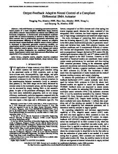
Fig.2. Output y1 (solid line) follows the reference y1,r (dotted line).
1.5
1
0.5
0
−0.5
−1
−1.5
0
5
10 seconds
15
20
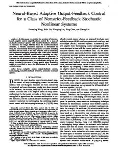
Fig.3. State estimate x ˆ1,1 (dotted line) follows state x1,1 (solid line).
Copyright (c) 2011 IEEE. Personal use is permitted. For any other purposes, permission must be obtained from the IEEE by emailing
[email protected].
This article has been accepted for publication in a future issue of this journal, but has not been fully edited. Content may change prior to final publication. IEEE TRANSACTIONS ON FUZZY SYSTEMS.
9
2
1.5
1.5 1 1 0.5 0.5 0
0
−0.5 −0.5 −1 −1 −1.5 −2
0
5
10 seconds
15
−1.5
20
Fig.4. State estimate x ˆ1,2 (dotted line) follows state x1,2 (solid line).
0
5
10 seconds
15
20
Fig.6. State estimate x ˆ2,1 (dotted line) follows state x2,1 (solid line).
1.5
2 1.5
1
1 0.5 0.5 0
0 −0.5
−0.5
−1 −1 −1.5 −1.5
0
5
10 seconds
15
−2
20
0
5
10 seconds
15
20
Fig.5. Output y2 (solid line) follows the reference y2,r (dotted line).
Fig.7. State estimate x ˆ2,2 (dotted line) follows state x2,2 (solid line).
Example 2. Consider two inverted pendulums connected by a spring with dead-zone inputs. Denoting x1,1 = θ1 (angular position), x1,2 = θ˙1 (angular rate), x2,1 = θ2 and x2,2 = θ˙2 . Angular rates x1,2 = θ˙1 and x2,2 = θ˙2 are unavailable. The equations which describe the motion of the pendulums are defined by x˙ 1,1 = x1,2 x˙ 1,2 = ( m1 gr − kr2 ) sin(x1,1 ) + kr (l − b) J1 4J1 2J1
inertia, k = 10 N/m is the spring constant of the connecting spring, r = 0.1 m is the pendulum height, l = 0.5 m is the natural length of the spring, and g = 9.81 m/s2 is gravitational acceleration. The distance between the pendulum hinges is defined as b = 0.4 m. In the example, choose b < l so that the pendulums repel one another when both are in the upright position. kr 2 sin(x2,1 ), f2,1 (x2,1 ) = where f1,1 (x1,1 ) = 0, f1,2 (x) = 4J 1 kr 2 0, f2,2 (x) = 4J2 sin(x1,2 ), d1,1 (x) = 0, d1,2 (x) = ( mJ11gr − m2 gr kr kr 2 kr 2 4J1 ) sin(x1,1 )+ 2J1 (l−b), d2,2 (x) = ( J2 − 4J2 ) sin(x2,1 )+ kr 2J2 (l − b), d2,1 (x) = 0. The parameters in the dead-zone model (2) are selected as: m1r = 1.5, m1l = 1, b1r = 2, b1l = 1, m2r = 3, m2l = 4, b2r = 3 and b2l = 2. Choosing fuzzy membership functions as: (ˆ x −6+2l)2 x2,1 ) = exp[− 2,1 2 x1,2 ) = µF1,2 ], µF2,2 l (ˆ l (ˆ
kr 2 sin(x2,1 ) + uJ11 + 4J 1 y = x1,1 1 x˙ 2,1 = x2,2 x˙ 2,2 = ( m2 gr − kr2 ) sin(x2,1 ) + J2 4J2
+ uJ22 +
2
kr 4J2
(80) kr 2J2 (l
− b)
sin(x1,2 )
y2 = x2,1
The parameter m1 = 2 kg and m2 = 2 kg are the pendulum end masses, J1 = 1 kg and J2 = 1 kg are the moments of
(ˆ x
−3+l)2
], l = 1, · · · , 5. exp[− 1,2 3 Define fuzzy basis functions P5 as: and ϕ2,2,l (ˆ x1,2 ) ϕ1,2,l (ˆ x2,1 ) = µF1,2 k l / k=1 µF1,2
=
Copyright (c) 2011 IEEE. Personal use is permitted. For any other purposes, permission must be obtained from the IEEE by emailing
[email protected].
This article has been accepted for publication in a future issue of this journal, but has not been fully edited. Content may change prior to final publication. IEEE TRANSACTIONS ON FUZZY SYSTEMS.
10
5
8
4
6
3 4 2 2
1 0
0
−1
−2
−2 −4 −3 −6
−4 −5
0
5
10 seconds
15
20
Fig.8. Control inputs v1 and v2 (dotted line). µF2,2 l /
−8
0
5
10 seconds
15
20
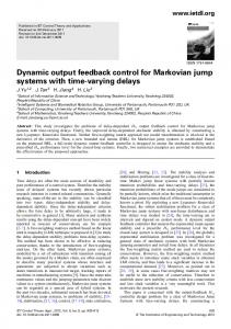
Fig.10. State estimate x ˆ1,1 (dotted line) follows state x1,1 (solid line).
P5
k , l = 1, · · · , 5. k=1 µF2,2 T Fuzzy logic systems fˆ1,2 (ˆ x2,1 |θ1,2 ) = θ1,2 ϕ1,2 (ˆ x2,1 ) and T ˆ f2,2 (ˆ x1,2 |θ2,2 ) = θ2,2 ϕ2,2 (ˆ x1,2 ) are obtained. Give a positive definite matrix Q1 = Q2 = diag{30, 30}, and select the design parameters k1,1 = 3, k1,2 = 25, k2,1 = 4, k2,2 = 50, we can construct the fuzzy state observer (21). Choose the first intermediate control function αi,1 (42) and the control input vi (69) and the parameters update laws (43), (44) and (70). The design parameters are selected as follows: c1,1 = 2, c1,2 = 7, c2,1 = 3, c2,2 = 8, γ1,2 = 8, γ2,2 = 8, σ1,2 = 4, σ2,2 = 5, τ1 = τ2 = 20. In the simulation, the initial conditions are chosen as x1,1 (0) = π/10 and the others initial values are chosen zeros. The reference signals are y1,r = 5 sin(t) + 2 sin(0.5t) and y2,2 = 3 cos(2t) + cos(t). The simulation results are shown in Figs. 9-15.
8 6 4 2 0 −2 −4 −6 −8
0
5
10 seconds
15
20
Fig.11. State estimate x ˆ1,2 (dotted line) follows state x1,2 (solid line).
8 6 4 2 0 −2 −4 −6 −8
0
5
10 seconds
15
20
Fig.9. Output y1 (solid line) follows the reference y1,r (dotted line). VI. C ONCLUSION In this paper, an adaptive fuzzy output feedback backstepping control approach has been developed for a class of nonlinear MIMO systems with unknown non- symmetric dead-zone
inputs and immeasurable states. Fuzzy logic systems were first used to approximate the unknown nonlinear functions and then a fuzzy state observer was designed for estimating the unmeasured states. Based on the backstepping recursive design technique and the information of the bounds of the dead-zone slopes and treating the time-varying inputs coefficients as a system uncertainty, an adaptive fuzzy backstepping control approach has been synthesized. It has been proved that all the signals of the resulting closed-loop control system are SGUUB, and the observer and tracking errors converge to a small neighborhood of the origin. The proposed adaptive fuzzy control approach can solve the problem of the unknown dead zones studied by the previous cited literature. Moreover, the restrictive condition imposed on the previous literature that all the states of the controlled nonlinear systems must be available for measurement may be neglected, thus the proposed control approach has extended the existing results in the previous literature.
Copyright (c) 2011 IEEE. Personal use is permitted. For any other purposes, permission must be obtained from the IEEE by emailing
[email protected].
This article has been accepted for publication in a future issue of this journal, but has not been fully edited. Content may change prior to final publication. IEEE TRANSACTIONS ON FUZZY SYSTEMS.
11
5
8
4
6
3 4 2 2
1 0
0
−1
−2
−2 −4 −3 −6
−4 −5
0
5
10 seconds
15
20
Fig.12. Output y2 (solid line) follows the reference y2,r (dotted line). 5
−8
0
5
10 seconds
15
20
Fig.14. State estimate x ˆ2,2 (dotted line) follows state x2,2 (solid line).
20
4
15
3 10 2 5
1 0
0
−1
−5
−2 −10 −3 −15
−4 −5
0
5
10 seconds
15
20
Fig.13. State estimate x ˆ2,1 (dotted line) follows state x2,1 (solid line).
R EFERENCES [1] Y. P. Zhang, P. Y. Peng, and Z. P. Jiang, “Stable neural controller design for unknown nonlinear systems using backstepping,” IEEE Trans. Neural Netw., vol. 11, no. 6, pp. 1347-1360, 2000. [2] Y. S. Yang, and C. J. Zhou, “Adaptive fuzzy H∞ stabilization for strictfeedback canonical nonlinear systems via backstepping and small-gain approach,” IEEE Trans. Fuzzy Syst., vol. 13, no. 1, pp. 104-114, 2005. [3] S. S. Zhou, G. Feng, and C. B. Feng, “Robust control for a class of uncertain nonlinear systems: adaptive fuzzy approach based on backstepping,” Fuzzy Sets Syst., vol.151, no.1, pp. 1-20, 2005. [4] J. H. Zhang, P. Shi, and Y. Q. Xia, “Robust adaptive sliding-mode control for fuzzy systems with mismatched uncertainties,” IEEE Trans. Fuzzy Syst., vol.18, no.4, pp.700-711, 2010. [5] Y. Q. Xia, H. J. Yang, P. Shi, and M. Y. Fu, “Constrained infinite-horizon model predictive control for fuzzy descrete-time systems,” IEEE Trans. Fuzzy Syst., vol.18, no.2, pp.429-436, 2010. [6] W. S. Chen, L. C. Jiao, R. H. Li and J. Li, “Adaptive backstepping fuzzy control for nonlinearly parameterized systems with periodic disturbances,” IEEE Trans. Fuzzy Syst., vol.18, no.4, pp.674-685, 2010. [7] W. S. Chen, and L. C. Jiao, “Adaptive NN backstepping output-feedback control for stochastic nonlinear strict-feedback systems with time-varying delays,” IEEE Trans. Syst., Man, Cybern. part-B, vol.40, no.3, pp.939950, 2010. [8] W. S. Chen, and L. C. Jiao, “Adaptive tracking for periodically timevarying and nonlinearly parameterized systems using multilayer neural networks,” IEEE Trans. Neural Netw., vol. 21, no. 2, pp. 345-351, 2010.
−20
0
5
10 seconds
15
20
Fig.15. Control inputs v1 and v2 (dotted line).
[9] T. P. Zhang H. Wen, and Q. Zhu, “Adaptive fuzzy control of nonlinear systems in pure Feedback form based on input-to-state stability,” IEEE Trans. Fuzzy Syst., vol.18, no.1, pp.80-93, 2010. [10] M. Wang, B. Chen, and P. Shi, “Adaptive neural control for a class of perturbed strict-feedback nonlinear time-delay systems,” IEEE Trans. Syst., Man, Cybern. part-B, vol.38, no.3, pp.721-730, 2008. [11] B. Chen, X. P Liu, K .F. Liu, P. Shi and C. Lin, “Direct Adaptive fuzzy control for nonlinear systems with time-varying delays,” Inf. Sci.,vol. 180, no. 5, pp. 776-792, 2010. [12] B. Chen, X.P. Liu, K.F Liu, and C. Lin, “Fuzzy-approximation-based adaptive control of strict-feedback nonlinear systems with time delays,” IEEE Trans. Fuzzy Syst., vol.18, no.5, pp.883-892, 2010. [13] C. C. Hua, X. P. Guan, and P. Shi, “Robust output tracking control for a class of time-delay nonlinear using neural network,” IEEE Trans. Neural Netw., vol. 18, no. 2, pp. 495-505, 2007. [14] C. C. Hua, Q. G. Wang, and X. P. Guan, “Adaptive fuzzy outputfeedback controller design for nonlinear time-delay systems with unknown control direction,” IEEE Trans. Syst., Man, Cybern. part-B, vol. 39, no. 2, pp. 363-374, 2009. [15] S. C. Tong, X. L. He, and H. G. Zhang, “A combined backstepping and small-gain approach to robust adaptive fuzzy output feedback control,” IEEE Trans. Fuzzy Syst., vol. 17, no. 5, pp. 1059-1069, 2009. [16] Q. Zhou, P. Shi, J. J. Lu, and S. Y. Xu, “Adaptive output feedback fuzzy tracking control for a class of nonlinear systems,” IEEE Trans. Fuzzy Syst., vol. 19, no. 5, pp. 972-982, 2011. [17] W. S. Chen, Z. Q. Zhang, “Globally stable adaptive backstepping fuzzy control for output-feedback systems with unknown high-frequency gain sign,” Fuzzy Sets Syst., vol.161, no. 6, pp. 821-836, 2010.
Copyright (c) 2011 IEEE. Personal use is permitted. For any other purposes, permission must be obtained from the IEEE by emailing
[email protected].
This article has been accepted for publication in a future issue of this journal, but has not been fully edited. Content may change prior to final publication. IEEE TRANSACTIONS ON FUZZY SYSTEMS.
[18] W. S. Chen and J. M. Li,“Decentralized output-feedback neural control for systems with unknown interconnections,” IEEE Trans. Syst., Man, Cybern. part-B, vol. 38, no. 1, pp. 258-266, 2008. [19] S. S. Ge, and C. Wang, “Adaptive neural control of uncertain MIMO nonlinear systems,” IEEE Trans. Neural Netw., vol. 15, no. 3, pp. 674692, 2004. [20] B. Chen, X. P. Liu, and S. C. Tong, “Adaptive fuzzy output tracking control of MIMO nonlinear uncertain systems,” IEEE Trans. Fuzzy Syst., vol. 15, no. 2, pp. 287-300, 2007. [21] B. Chen, X. P. Liu, K. Liu and C. Lin, “Novel adaptive neural control design for nonlinear MIMO time-delay systems,” Automatica, vol.46, no.7, pp.1554-1560, 2009. [22] H. Lee, “Robust adaptive fuzzy control by backstepping for a class of MIMO nonlinear systems,” IEEE Trans. Fuzzy Syst., vol.19, no.2, pp.265 - 275, 2011. [23] T. S. Li, S. C. Tong, and G. Feng, “A novel robust adaptive-fuzzytracking control for a class of nonlinear MIMO systems,” IEEE Trans. Fuzzy Syst., vol.18, no.1, pp.150-160, 2010. [24] S. C. Tong, C. Y. Li, and Y. M. Li, “Fuzzy adaptive observer backstepping control for MIMO nonlinear systems,” Fuzzy Sets Syst., vol.160, no. 19, pp. 2755-2775, 2009. [25] C. S. Chen, “Robust self-organizing neural-fuzzy control with uncertainty observer for MIMO nonlinear systems,” IEEE Trans. Fuzzy Syst., vol.19, no.4, pp.694-706, 2011. [26] S. C. Tong, C. L. Liu, and Y. M. Li, “Fuzzy-adaptive decentralized output-feedback control for large-scale nonlinear systems with dynamical uncertainties,” IEEE Trans. Fuzzy Syst., vol.18, no.5, pp.845-861, 2010. [27] G. Tao, and P. V. Kokotovic, “Adaptive sliding control of plants with unknown dead-zone” IEEE Trans. Autom. Control, vol. 39, no. 1, pp. 59-68, 1994. [28] M. Tian, and G. Tao, “Adaptive dead-zone conpensation for outputfeedback canonical systems discrete-time adaptive control of systems with unknown dead-zone,” Int. J. Control, vol. 67, no. 5, pp. 791-812, 1997. [29] H. Y. Cho, and E. W. Bai, “Convergence results for an adaptive dead zone inverse,” Int. J. Adapt. Control Signal Process, vol. 12, no. 5, pp. 451-466, 1998. [30] A. Taware, and G. Tao, “An adaptive dead-zone inverse controller for systems with sandwiched dead-zones,” Int. J. Control, vol. 76, no. 8, pp. 755-769, 2003. [31] X. S. Wang, H. Hong, and C. Y. Su, “Model reference adaptive control of continuous time systems with an unknown dead-zone,” Inst. Electr. Eng. Proc.-Control Theory Appl., vol. 150, no. 3, pp. 261-266, 2003. [32] J. Zhou, “Decentralized adaptive control for large-scale time-delay systems with dead-zone input,” Automatica, vol.44. no. 7, pp.1790-1799, 2008. [33] X. S.Wang, H. Hong and C. Y. Su, “Robust adaptive control a class of nonlinear systems with an unknown dead-zone,” Automatica, vol. 40, no. 3, pp. 407-413, 2004. [34] S. Ibrir, W. F. Xie, and C. Y. Su, “Adaptive tracking control of nonlinear systems with non-symmetric dead-zone inputs,” Automatica, vol.43. no. 3, pp.522-530, 2007. [35] C. Y. Su, M. Oya, and H. Hong, “Stable adaptive fuzzy control of nonlinear systems preceded by unknown backlash-like hysteresis,” IEEE Trans. Fuzzy Syst., vol.11, no.1, pp.1-8, 2003. [36] A. Boulkroune, M. M’Saad, and H. Chekire, “Design of a fuzzy adaptive controller for MIMO nonlinear time-delay systems with unknown actuator nonlinearities and unknown control direction,” Inf. Sci., vol. 180, no. 24, pp. 5041-5059, 2010. [37] Q. K. Shen, T. P. Zhang, and C. Y. Zhou, “Decentralized adaptive fuzzy control of time-delayed interconnected systems with unknown backlash-like hysteresis,” J. Systems Engineering Electronics, vol.19. no.6, pp.1235-1242, 2008. [38] T. P. Zhang, and S. S. Ge, “Adaptive dynamic surface control of nonlinear systems with unknown dead zone in pure feedback form,” Automatica, vol. 44, no. 7, pp. 1895-1903, 2008. [39] T. P. Zhang, and S. S. Ge, “Adaptive neural control of MIMO nonlinear state time- varying delay systems with unknown dead-zones and gain signs,” Automatica, vol.43, no.6, pp.1021-1033, 2007. [40] T. P. Zhang, and S. S. Ge, “Adaptive neural network tracking control of MIMO nonlinear systems with unknown dead zones and control directions,” IEEE Trans. Neural Netw., vol. 20, no. 3, pp. 483-497, 2009. [41] S. C. Tong, and Y. M. Li, “Adaptive fuzzy output feedback tracking backstepping control of strict-feedback nonlinear systems with unknown dead zones,” IEEE Trans. Fuzzy Syst., vol. 20, no. 1, pp.168-180, 2012. [42] L. X. Wang, Adaptive fuzzy systems and control, Prentice Hall Englewood Cliffs, NJ, 1994.
12
[43] A. B. Cara, H. Pomares, and I. Rojas, “A new methodology for the online adaptation of fuzzy self-structuring controllers,” IEEE Trans. Fuzzy Syst., vol. 19, no. 3, pp.449-464, 2011. [44] Y. G. Leu, T. T. Lee, and W. Y. Wang,“Observer-based adaptive fuzzyneural control for unknown nonlinear dynamical systems,” IEEE Trans. Syst., Man, Cybern. part-B, vol. 29, no. 5, pp. 583-591, 1999. [45] W. Y. Wang ,Y. H. Chien, and T. T. Lee, “Observer-based T-S fuzzy control for a class of general nonaffine nonlinear systems using generalized projection-update laws,” IEEE Trans. Fuzzy Syst., vol.19, no.3, pp.493-504, 2011. [46] Y. Q. Xia, M. Y. Fu, P. Shi, Z. J. Wu, and J. H. Zhang, “Adaptive backstepping controller design for stochastic jump systems, ” IEEE Trans. Autom. Contr., vol.54, no.12, pp.2853-2859, 2009. [47] M. M. Polycarpou, “Stable adaptive neural control scheme for nonlinear systems, ” IEEE Trans. Autom. Contr., vol.41, no.3, pp. 447-451, 1996.
Shaocheng Tong received the B.S. degree in mathematics from Jinzhou Normal College, Jinzhou, China, the M.S. degree in fuzzy mathematics from Dalian Marine University, Dalian, China, and the Ph.D. degree in fuzzy control from the Northeastern University, Shenyang, China, in 1982, 1988, and 1997, respectively. He is currently a Professor with the Department of Basic Mathematics, Liaoning University of Technology, Jinzhou, China. His current research interests include fuzzy and neural networks control theory, and nonlinear adaptive control.
Yongming Li received the B.S. degree and the M.S. degree in applied mathematics from Liaoning University of Technology, Jinzhou, China, in 2004 and 2007, respectively. He is currently a lecturer in the Department of Basic Mathematics, Liaoning University of Technology, Jinzhou, China. Now, He is pursuing his Ph.D. degree in transportation information engineering and control in Dalian Maritime University, Dalian, China. His current research interests include fuzzy and neural networks control theory, and nonlinear adaptive control.
Copyright (c) 2011 IEEE. Personal use is permitted. For any other purposes, permission must be obtained from the IEEE by emailing
[email protected].