Hindawi Publishing Corporation International Journal of Reconfigurable Computing Volume 2012, Article ID 298561, 14 pages doi:10.1155/2012/298561
Research Article Adaptive Multiclient Network-on-Chip Memory Core: Hardware Architecture, Software Abstraction Layer, and Application Exploration Diana G¨ohringer,1, 2 Lukas Meder,3 Stephan Werner,3 Oliver Oey,3 J¨urgen Becker,3 and Michael H¨ubner4 1 Institute
for Data Processing and Electronics, Karlsruhe Institute of Technology, 76344 Eggenstein-Leopoldshafen, Germany Recognition Department, Fraunhofer IOSB, 76275 Ettlingen, Germany 3 Institute for Information Processing Technology, Karlsruhe Institute of Technology, 76128 Karlsruhe, Germany 4 Chair for Embedded Systems in Information Technology, Ruhr-University of Bochum, 44780 Bochum, Germany 2 Object
Correspondence should be addressed to Diana G¨ohringer,
[email protected] Received 4 May 2012; Accepted 3 October 2012 Academic Editor: Ren´e Cumplido Copyright © 2012 Diana G¨ohringer et al. This is an open access article distributed under the Creative Commons Attribution License, which permits unrestricted use, distribution, and reproduction in any medium, provided the original work is properly cited. This paper presents the hardware architecture and the software abstraction layer of an adaptive multiclient Network-on-Chip (NoC) memory core. The memory core supports the flexibility of a heterogeneous FPGA-based runtime adaptive multiprocessor system called RAMPSoC. The processing elements, also called clients, can access the memory core via the Network-on-Chip (NoC). The memory core supports a dynamic mapping of an address space for the different clients as well as different data transfer modes, such as variable burst sizes. Therefore, two main limitations of FPGA-based multiprocessor systems, the restricted on-chip memory resources and that usually only one physical channel to an off-chip memory exists, are leveraged. Furthermore, a software abstraction layer is introduced, which hides the complexity of the memory core architecture and which provides an easy to use interface for the application programmer. Finally, the advantages of the novel memory core in terms of performance, flexibility, and user friendliness are shown using a real-world image processing application.
1. Introduction and Motivation Due to the increasing number of available logic blocks on today’s Field Programmable Gate Arrays (FPGAs), complete multiprocessor systems can be realized on FPGA. Compared to traditional application specific integrated circuit (ASIC) solutions these FPGA-based Multiprocessor Systems-onChip (MPSoCs) can be realized-with lower costs and a shorter (re)design cycle, due to the flexible hardware architecture of the FPGA, which can be adapted to the needs of the application. However, the major limitations of these FPGA-based MPSoCs are the limited on-chip memory resources as well as the limited physical connection to an off-chip memory. A possible solution would be to connect each processing element to its own external memory. However, this would result
in a very specific board design and reduce the flexibility of such an FPGA-based solution. Moreover, due to different application scenarios, the memory requirements of a processor can vary at design and runtime. This is in particular the case, if runtime adaptive MPSoCs, such as RAMPSoC [1], are considered, which support the modification of the MPSoC hardware architecture (number and type of processing elements, communication infrastructure, etc.) as well as the runtime adaptation of the software. To resolve the memory bottleneck for FPGA-based MPSoCs, an adaptive multiclient Network-on-Chip (NoC) memory core has been developed [2]. This intelligent memory core can support between 1 and 16 processing cores, so-called clients, via an NoC. The clients and their memory allocation are managed dynamically. This is an important feature for adaptive MPSoCs, such as RAMPSoC, which use
2 dynamic and partial reconfiguration for runtime adaptation of both hardware and software. An additional benefit of this dynamic memory allocation is the support of the so-called “virtual-data transfers” by mapping very fast larger memory blocks from one client to another. For the data transfer a priority-based scheduling approach is used to guarantee the access with a negotiated delay. At runtime the priorities can be adapted dynamically, for example, due to application requirements or for example, due to the fact that the data have to be transferred periodically from a source (image sensor). To hide the complexity of the adaptive multi-client NoC memory core, a software abstraction layer has been developed and integrated. This software abstraction layer provides a user-friendly interface to all the aforementioned features and is based on the well-known message passing interface (MPI) programming model [3]. The benefits of this intelligent memory core are evaluated for executing an image processing application on RAMPSoC. Performance results with and without the software abstraction layer are shown and compared against a standard connection to external memory by using the processor local bus (PLB) [4] and the Xilinx MultiPort Memory Controller (MPMC) [5]. The paper is organized as follows. Related work is presented in Section 2. RAMPSoC is briefly introduced in Section 3. In Section 4 and its subsections, the functionality and the hardware architecture of the adaptive multi-client NoC memory core are presented. In Section 5 the software abstraction layer is introduced. The image processing application used for the evaluation is presented in Section 6. In Section 7 the integration of the adaptive memory core and the software abstraction layer into the RAMPSoC approach together with measured performance results are given. Finally, the paper is closed by presenting the conclusions and future work in Section 8.
2. Related Work This work exploits the Multi-Port Memory Controller (MPMC) from Xilinx [5], which supports from 1 up to 8 channels connected to one memory block. The core itself supports multiple connection standards which are tailored to the processors used in Xilinx-based designs (Microblaze, Power PC). Furthermore, low-level direct access ports to the memory called Native Port Interface (NPI) are supported which were used for the core described in this paper. The idea to connect a memory via a network node in an NoC was also used in the heterogeneous multicore System-on-Chip MORPHEUS [6]. The controller enabled a data transfer to and from an ARM9 processor as well as to different reconfigurable hardware blocks. As in the MORPHEUS project an ASIC was developed, the area optimization like it is required in FPGA-based designs was not that critical. Furthermore, in MORPHEUS, the clients in the NoC were fixed and not adaptive in that extent, as in the here presented NoC. Intelligent memory controllers were successfully realized in previous research works. Intelligence had been integrated
International Journal of Reconfigurable Computing into the memory itself, so that it is able to process data without the host processor and therefore results in a higher performance (see [7, 8]). Especially, FlexRAM and SelfAware Memory (SAM) were developed for this purpose and the decentral management of large memory. The approach presented in this paper benefits definitely from the excellent ideas in these works, but targets directly the support of a runtime adaptive FPGA-based MPSoC and an NoC built especially for this purpose. Additionally, the focus of this work is not to increase the performance of a processor through a memory internal data manipulation, but rather to enable the flexible access of an FPGA-based system to an external memory block. A good example for scheduling algorithms for multiport memory controllers is given in Dai and Zhu [9]. They propose a quality of service guaranteed scheduling algorithm which is based on a combination of weighted round robin, credit borrow, and repay and residual bandwidth calculation. The approach is very interesting, but the dynamic change of clients due to dynamic and partial reconfiguration of the MPSoC at runtime is not supported by the algorithm. Also a connection to this MPMC via an NoC is not considered. Redsharc [10] presents a software API based on the stream model for hiding the complexity of accessing onand off-chip memory via their proprietary Block Switch NoC (BSN) and the Xilinx MPMC controller. However, also in this work runtime adaptation of the system is not supported. In summary, the major contributions of this work compared to related works are the combination of a flexible multiclient NoC memory core with an MPI-based software abstraction layer for a runtime adaptive MPSoC. The approach presented in this paper, can efficiently be integrated into the Aethereal NoC (see [11]), which has a high importance in current research projects such as FlexTiles (see [12]). The Aethereal NoC is used in the FlexTiles project, to establish the intertile communication and for the data transfer from and to the on-chip and external memory blocks. The adaptive multi-client Network-on-Chip memory core presented in this paper can be efficiently exploited for this innovative multicore architecture. The concept and its efficient realization are described in the following sections.
3. Runtime Adaptive MPSoC: RAMPSoC RAMPSoC [1] is an FPGA-based heterogeneous MPSoC consisting of different types of processors and hardware accelerators which communicate with each other and with the environment over the Star-Wheels Network-on-Chip [1]. The Star-Wheels NoC has a heterogeneous topology consisting of three different kinds of switches: subswitch, superswitch, and rootswitch. Each processing element is connected via a network interface (NI) to a subswitch. For this purpose, a unified NI based on the Xilinx FIFObased Fast Simplex Links (FSL, [13]) is used. The superand the rootswitch are used as central network nodes. The superswitch connects up to seven subswitches into a socalled subnet. The rootswitch is used as the central node for
International Journal of Reconfigurable Computing
FPGA
3
Complete Star-Wheels NoC with 4 PEs 44 3 PE2 5 Subnet 2 2 2 Subnet 1 66 PE1 2 66 77 1 3 1 5 7
Micro processor (type 2)
Subnet 1
11
4 5 User applications
External memory
Control processor
FSM + hardware function
Subnet 4
Micro processor (type 1)
66
33
0 71
1 7 44
2 Subnet 4 3
4
2
4 3
PE3 Subnet 3 5 PE4 6
Accelerator FSL-ICAP
Accelerator 1
Micro processor (type 1) Accelerator 2
Virtual-I/O Accelerator 3
: subswitch : superswitch
: rootswitch PE
: processing element
Figure 1: Example RAMPSoC system at one point in time connected over the Star-Wheels Network-on-Chip.
connecting up to four subnets with each other. The StarWheels NoC provides both a packet- and a circuit-switching communication protocol using separate ports for each protocol. The packet-switching communication protocol is used for control purposes, such as establishing/freeing a circuitswitching communication, and for small data transfers. Per packet 16 bits of data can be transferred. For high data volumes the circuit-switching communication protocol is preferred, as it has a lower latency and supports a data width of 32 bits. Using dynamic and partial reconfiguration, the MPSoC can be adapted at runtime to the application requirements, for example, changing the number and type of processors and accelerators, modifying the communication infrastructure or changing the software executables. In Figure 1, an example RAMPSoC architecture at one point in time is shown. To hide the complex heterogeneous MPSoC architecture from the user, a virtualization layer has been developed (for details see [14]). It consists of an embedded Linux server, which is responsible for scheduling and mapping of the software and hardware adaptations. It furthermore acts as a user interface. This Linux server communicates and controls the slave processors. The slave processors execute a special purpose operating system called ELEX-OS (ELF executing operating system). Both ELEX-OS and the embedded Linux operating system include proprietary communication libraries based on MPI to facilitate the communication over the Star-Wheels NoC and to hide the low level communication protocol routines.
4. Functionality and Structure of the Adaptive Memory Core The main goal when designing the runtime adaptive memory core was to make it adaptable to both changing conditions from the information’s point of view and to changes at the component’s interfaces. In more detail, the memory core should on the one hand be flexible to support the following: (i) priority based scheduling of the processor accesses; (ii) adapting the priorities of the processors on demand; (iii) dynamic management of varying numbers of processors, several requests at the same time, and different memory requirements due to changing applications; (iv) up to 16 distinct processor peripherals which are provided overlap-free virtual memory resources which are dynamically managed. On the other hand, the memory core should have a modular structure supporting a high portability to be independent from the NoC as well as from the number and types of off-chip memory cores. Therefore, the adaptive memory core is connected via FSL [13] to the Star-Wheels NI and therefore to the Star-Wheels NoC. As most of these functionalities are handled by the NI the memory core is this way decoupled from the Star-Wheels NoC. Also the memory core’s complexity at the packet evaluation stage is reduced because it only receives the packets and data which are meant for it. It is linked to the MPMC via two NPI ports
4
International Journal of Reconfigurable Computing
Star-Wheels Network-on-Chip
Control FSL
Data FSL
Memory controller
Data Access controller Control FSL (logical address)
Address generator 0
Address generator 1
Address generator . . .N − 1
···
Address generator N
Memory access information (physical address) Memory access controller
NPI WR
NPI RD
MPMC
Memory banks
Figure 2: Overview of the adaptive memory core.
(one to write and one to read) which is the native interface to the manufacturer’s memory controller. The MPMC can be configured for a variety of different types of off-chip memory and it is frequently updated by Xilinx to support the newest memory types. Currently the MPMC core provides 8 ports which support a variety of bus standards. In Figure 2, the structure of the adaptive memory core and its interfaces to the off-chip memory and the StarWheels NoC is depicted. Both routing protocols supplied by the Star-Wheels NoC are supported. The memory core is connected to the packetswitching lines via the control-FSL which is solely used for control purposes such as memory de- and allocation or changing the priority of a processor. Reading or writing data from/to the external memory is done using the faster circuitswitching communication protocol via the parallel dataFSL port. The reason for using only the circuit-switching communication for the data exchange is on the one side the wider data width of 32 bits compared to 16 bits of the packet-switching protocol. On the other side, the overhead for accessing external memory is higher than accessing local on-chip memory and should therefore be only used for exchanging high amount of data, which is faster via the circuit-switching protocol due to the low latency.
The aforementioned capability to manage 16 distinct processors by one memory core was selected according to the maximum number of devices which can be connected to the NoC (see the right part of Figure 1). With growing numbers of devices to be managed, the required logic resources, and the communication load at the network node the memory core is connected to do also increase. Thus, 16 supported processors were found as a good tradeoff between the required area and the flexibility of the memory core. In order to reduce latency, simplify the design and increase portability; the control and data paths are decoupled. The paths are separated at the NI and are reunited at the memory access controller. As can be seen in Figure 2, there is no intermediate processing of the data path that would add latency or deteriorate the throughput of the high speed data transmission. Internally the adaptive memory core consists of three main components: access controller, 1 to 16 address generators, and the memory access controller. These components are explained in detail in the following subsections. 4.1. Access Controller. The access controller is the administrating component that evaluates priority and memory allocation requests, registers devices, and decides in resource assignments to the address generators.
International Journal of Reconfigurable Computing Prior to storing or reading data to/from a memory location of the external memory that is connected to the memory core, memory regions need to be allocated to the processors. The memory allocation is based on blocks with a fixed number and size. For the implementations and results 64 blocks at 64 kbytes each were selected. 64 kbytes were chosen as a minimal block size, because for smaller amounts of bytes the FPGA has sufficient on-chip resources, which can be accessed faster than the external memory. Also, this selection allows providing the needed flexibility by keeping the complexity and therefore the area requirements of the adaptive memory core low. Both parameters can be adapted to the users need at design time. Each time a processor allocates memory blocks, the access controller informs the respective address generator about the corresponding block numbers. These block numbers are then later used by the address generators to translate the logical addresses of the processor requests into the physical addresses of the MPMC controller. The access controller stores internally the index of the current block and the index of the next free block. On the allocation or deallocation of a block both indexes are increased or decreased, respectively. For the deallocation process a simple, yet effective, scheme for block-based allocation is applied. The basic idea is to store the block numbers of deallocated blocks in a socalled deallocation array. If an allocated block is freed by a processor, the block number is copied to the top position of the deallocation array and the indexes of the current/next block are decreased by one. When the allocation of a block is requested, first it is checked, if the deallocation array holds a block number. If this is the case, this block is reused and both indexes are left unchanged, if not, a new block is allocated by increasing both indexes. Like this, fragmentation is avoided and the required memory resources are minimized. Illegal deallocation or allocation requests are denied by the access controller by sending a not OK (NOK) packet. Such deallocations or allocations are defined as requests where a processor wants to deallocate a nonexistent block or allocate a block when all blocks are being used. On the other hand, if an allocation/deallocation was successful the associated address generators reply by sending an OK packet to the requesting processor. In order to reduce network traffic it is allowed to allocate/deallocate multiple blocks at a time. This is done by setting the lower six bits of the allocation packet to the desired number of blocks. Here the address generator always answers such packets with an OK packet which contains the number of allocated blocks. It is then in the processors’ responsibility to check, if the requested number of blocks was allocated. If the number of allocated blocks was too low, the remaining blocks could not be allocated, because all blocks were in use when the request was being processed. In the process of memory allocation the address generators only play a minor role. The computed number of a newly allocated memory block is forwarded to the assigned address generator on a memory allocation. When a block needs to be deallocated the number of the last allocated block is obtained from the address generator and added to the deallocation array.
5 The access controller has an assignment table, in which the address of each processor is assigned to one address generator. New processors will be assigned to the next free address generator. In case of 16 address generators up to 16 processors can access the memory core. No dedicated control packet is required for the registration of a processor because every control packet contains the processor’s unique address in the NoC as defined by the communication protocol. Through this scheme the memory core behaves as a coherent module hiding the information about the internal details from connected devices. Packets related to memory accesses or for establishing and freeing a circuit-switching channel are directly forwarded to the respective address generator. In addition, the access controller is responsible for updating the priorities of the address generators based on the requests of the assigned processors. In order to keep the priority encoder simple and to assure that each address generator is assigned to a single priority and vice versa, the processors can only request to increase/decrease the current priority of their address generator by 1. If, for example, the priority of one address generator has to be increased by 1, the access controller searches in its internal priority table for the address generator which has currently the desired priority. Then the priorities of these two address generators are switched. Due to this switch, it occurs that the priority of an address generator is changed by the priority change request of a different processor. Therefore, each processor can send a so-called get-priority-packet to the access controller before accessing the memory, in order to request its current priority level and to decide if it will be necessary to increase the own priority before accessing the memory. For all memory accesses and transfers via the controlFSL, the access controller assigns available resources to the address generators based on a priority table. The requesting address generator which has currently the highest priority gets the access to the component. If all resources of a kind are being used, the remaining requests are postponed until the next time one of the required resources is released by an address generator. In order to guarantee high throughput for different processors in data-driven applications, the idle time between assignments of the connections to the memory access controller has to be kept at a small value. Thus a second interface to both the NoC and the memory controller was introduced as presented in Section 4.5. To be able to evaluate requests for a change of priorities during memory accesses or allocations and to avoid resource sharing problems during these processes, a second priority table is introduced that stores these changes. If a priority change has to be applied new resource assignments are postponed and the contents of the second priority table are copied to the first one as soon as all resources have been released. 4.2. Address Generator. Each processor is assigned to an address generator. The address generators receive the packets, which have been sent by the processors via the packetswitching communication protocol and which include either
6 information about the desired memory access or information for establishing or freeing a circuit-switching communication channel for the requested data transfer. The address generators work independently from each other and primarily serve the processors on handling requested memory accesses and controlling the establishment and freeing of the circuit-switching channels required for the data transmission to or from the MPMC core. However, for addressing a specific block of the allocated offchip memory space the logical address of the request needs to be translated into a physical memory address. For this reason, the address generator is equipped with an allocation array that stores the numbers of the allocated blocks which are forwarded from the access controller to the address generator. By evaluating the validity of incoming requests, the address generator guarantees that only these requests may be executed which are allowed due to restrictions of the memory access controller and which will not cause any corruption of data of other address generators’ address space. Requests which are evaluated as invalid are directly rejected (NOK packet). The computation of the physical addresses has to be performed by the address generator because the memory access controller itself has no information about the allocated block numbers of each address generator. Thus the physical addresses are generated as follows. First, the address generator controls if the address is a multiple of 32 bits (=4 bytes). This address alignment is selected because of the minimum portion of data (4 bytes) that can be transferred through the FSL connection between the memory core and the processor. Due to the 32-bit width of the FSL interface, an address which is not a multiple of 4 bytes would not be beneficial as parts of the data word would need to remain free in the first and in the last transmitted packet. Second, the address generator checks if the number of bytes to be transferred is also a multiple of 4 and therefore a multiple of 32 bits. If this is not the case, the number of bytes is rounded up to the next multiple of 4 bytes. Third, the address generator verifies, if sufficient memory blocks have been allocated for the respective memory access. This means, it assures that both the start address and the total transfer size are within the allocated address space of this address generator. If not or if the address is not a multiple of 4 bytes, a NOK packet will be sent to the processor. For all other cases, the address generator checks, if the requested memory transfer crosses the block boundary. This is important, as two successive logical blocks are not necessarily mapped to two successive physical memory blocks. In case the physical blocks are not successive the requested memory transfer is split into two transfers. The address of the physical block ap required for these checks is calculated by dividing the address of the access request ar by the block size b and multiplying the block number of the allocated block at the position “ar div b” of the allocation array by the block size b. The physical address is finally obtained by adding the rest of the division r as an offset to the base address of the physical block. The information for all transfers is then forwarded to the memory access controller. The maximum number
International Journal of Reconfigurable Computing of transfers per memory access is two, as the maximum access request is 4 kbytes based on the structure of the control packets as described in Section 4.4. As each block has 64 kbytes, only one block boundary can be crossed by a memory access resulting in a maximum of two transfers. Conflicts of different address generators trying to access the memory access controller or the control-FSL to send back packets to the processors at the same time must be avoided. Thus a shared access to these resources is applied. This scheme is implemented by assigning every address generator a specific priority, that is, a bijective transform is used. By guaranteeing unique priorities during the whole runtime, a simple encoder can be designed that decides which currently requesting address generator has the highest priority and grants access to the resource due to this decision. For the priorities a cooperative method with dynamic priorities and no preemption is used. Because of the bijectivity of the priority → address generator relation, the tasks of priority decision and priority update of the access controller can be eased by storing the inverse relation in the second priority table instead of a direct copy of the first one. 4.3. Memory Access Controller. The memory access controller receives the information for the transfer (physical memory address, number of bytes, read, or write) from the address generators and it handles the memory accesses by arbitrating and communicating with the MPMC controller. It translates the number of bytes to be transferred into the number of 64-bit words, because it accesses the MPMC via a 64-bit NPI interface. To minimize the communication load for the MPMC, all supported NPI transfer sizes will be used by preferring the maximum possible one based on the address alignment: 2, 4, 8, 16, 32, and 64 word transfers. If none of the chosen transfer sizes fits the address alignment and no smaller transfers have been computed during the initial phase, larger transfers have to be subdivided. Here, the smallest remaining transfer, which is larger than the transfer whose address alignment requirement would fit the circumstances, is consecutively divided into smaller transfers. An example is shown in Figure 3. Here one 64-word and one 32-word transfer is available but the address is aligned to an address boundary that would fit 8-word transfers only. In the proposed scheme, the 32word transfer is divided first into two 16-word transfers and afterwards one 16-word transfer is divided into two 8-word transfers. After one of the smallest transfers has been finished, step by step the address alignment allows larger transfer sizes. Due to this strategy the number of needed transfers and therefore the load on the MPMC are minimized. The memory access controller has a direct access to the circuit-switching communication ports of the StarWheels NI via the data-FSL component, as can be seen in Figure 2. Only the memory access controller is dependent on the MPMC controller. In case a different memory controller shall be used or in case Xilinx will stop the support of the MPMC and will offer a different memory controller, only the memory access controller needs to be adapted. All other components of the adaptive memory core are independent of the selected memory controller. This way,
International Journal of Reconfigurable Computing Initial condition
7 Transfer subdivision
Result
+
1 × 64-word transfer 1 × 32-word transfer Address aligned for 8-word transfers
1 × 32-word transfer 2 × 16-word transfers 1 × 16-word transfer 2 × 8-word transfers
1 × 64-word transfer 1 × 16-word transfer 2 × 8-word transfers
Figure 3: Transfer subdivision example.
a higher performance compared to a single NPI port can be achieved by slightly increasing the number of required FPGA resources. 4.4. Structure and Types of Control Packets. The basic structure of the control packets used for the memory core is shown in Figure 4. It is based on the so-called flexible packet [14] and uses the corresponding header. The flexible packets are provided by the Star-Wheels NoC to add user defined packets. The header is then followed by the destination address and the source address. The following four bits are used for the memory core header. This header allows differentiating between the different packets required for the functionality of the memory core. These are the following packets:
Header
31
Sourceaddress
Destinationaddress
27
21
Memory core header
15
Data
11
0
Figure 4: Basic structure of the control packets used for the memory core.
In the access information phase only a packet with Write/Read-flexible 3 header is mandatory. If the first two packets of the information phase are omitted, the address of the last read or write access, respectively, is used.
Get-priority, Decrease-priority, Increase-priority, Deallocate-block, Allocate-block, NOK (Not OK), OK, Write-flexible 1 (address part 1), Write-flexible 2 (address part 2), Write-flexible 3 (number of bytes), Read-flexible 1 (address part 1), Read-flexible 2 (address part 2), Read-flexible 3 (number of bytes). The 12 bits of data are used to transfer the required address, split in two parts (e.g., Write-flexible-packet 1 and 2), to transfer the number of bytes (e.g., Write-flexible-packet 3) or to specify, how many blocks to allocate/deallocate. The protocol for a memory access is composed of an access information phase and a channel handling phase using packet-switched routing and a data transmission phase using circuit-switched routing, see Figure 5.
4.5. Extension with Two Star-Wheels Network Interfaces. For very memory-intensive applications, where several processors have to frequently access the memory core, an extended version with two Star-Wheels NI ports and four NPI ports has been developed. An overview of this memory core version is shown in Figure 6. With this extended memory core version, two write and two read accesses can be processed simultaneously. To prevent waiting cycles, the memory access controller and the finite state machine of the access controller have been duplicated: one for each additional port. This results in a higher performance, but also in higher area requirements. For even more memory-intensive scenarios or to be able to access more memory space, the address space of the memory core can be modified by an offset at a design time to support more than one instance of the memory core in an NoC system.
5. Software Abstraction Layer 5.1. Motivation. Using the memory core in a C-program is not very simple. There are a lot of things which have to receive attention. For instance, for reading or writing data from or to the external memory using the memory core, a sequence of three low level commands for initializing the hardware must be used. Additionally, the buildup and release
8
International Journal of Reconfigurable Computing Access information phase FP1
FP2
FP3
Channel handling phase
OK/ NOK
Data transmission
Channel setup
Channel shutdown Time
FPx
- Write/read flexible packet x
OK/ NOK
- Confirmation/rejection packet from address generator
Packet-switched routing
Channel
- Circuit-switched routing setup/shutdown packets
Data
- High speed data transmission using circuit-switched routing
Figure 5: Memory access protocol.
Star-Wheels Network-on-Chip Control FSL Port0
Data FSL Port0
Control FSL Port1
Data FSL Port1
Memory controller Access controller
Data FSL
Control FSL (logical address)
Address generator 0
Address generator 1
Address generator . . .N − 1
···
Memory access information (physical address) Memory access controller 0
Address generator N
Memory access controller 1
NPI WR Port0
NPI WR Port1 NPI RD Port0
MPMC
NPI RD Port1
Memory banks
Figure 6: Overview of the adaptive memory core with four NPIs and two Star-Wheels NI ports.
of a communication channel must be handled. Furthermore, the programmer must calculate the amount of bytes to be transferred. For allocating memory with the memory core, the number of blocks of 64 kbytes, which is needed for this number of bytes, must be computed. After calculating this, the programmer has to keep in mind that the argument, specifying the number of blocks to allocate, must be
decreased by one. So “0” must be passed for allocating 1 block of 64 kbytes in external memory. Later, this number of blocks must be used for releasing the memory. To ease the usage of the memory core, some functions of the Message Passing Interface protocol (MPI) were implemented in the MPI library of RAMPSoC. Furthermore, the ELEX-OS running on the Microblazes connected to
International Journal of Reconfigurable Computing
9
Table 1: MPI functitons used for accessing the adaptive memory core. int MPI Alloc mem (MPI Aint size, MPI Info info, void ∗ baseptr) MPI Aint size Size of memory to be allocated in byte MPI Info info Usage depends on implementation; only the value 0 must be supported void∗ baseptr Pointer to the allocated memory int MPI Put (void ∗ origin addr, int origin count, MPI Datatype origin datatype, int target rank, MPI Aint target disp, int target count, MPI Datatype target datatype, MPI Win win) ∗ origin Defines which data shall be sent to the target node Defines where the data are to be sent: the node (by rank), in which local memory address ∗ target (target disp) and the amount of data win Defines the memory window on target int MPI Get (void ∗ origin addr, int origin count, MPI Datatype origin datatype, int target rank, MPI Aint target disp, int target count, MPI Datatype target datatype, MPI Win win) origin ∗ Defines where the data which are read from target shall be stored Defines which data shall be read: from which node (by rank), from which local memory address target ∗ (target disp), and the amount of data win Defines the memory window on target int MPI Free mem(void ∗ base) void ∗ base Pointer to the memory that was allocated with MPI Alloc mem
the NoC was extended for handling the access to the memory core. Additionally, ELEX-OS provides a special memory management to handle the needs for allocating and freeing local and external memory using the corresponding MPI functions. Implementing the new MPI functions in the library, we are aware to support the MPI standard as much as possible, but because of the special features and restrictions of the embedded architecture some modification are needed. 5.2. Normal Use of the MPI Functions. Before describing the adaptations, it is explained how the usage of the functions listed in Table 1 is defined in the standard of MPI. The function MPI Alloc mem() allocates storage in memory and returns a pointer to it. This pointer is stored in the third argument “baseptr” of the function. The second argument “info” of the function is not standardized. The meaning and the accepted values for “info” depend on the implementation of the MPI library. The standard only defines that the value MPI INFO NULL (=0) must be accepted always. The function MPI Free mem() is then used for freeing this memory again. In MPI, there is a possibility for transferring data between the memories of several nodes in the same communicator. For this purpose the corresponding nodes must allow each task in the intracommunicator group to access their local memory. Therefore the nodes must specify a “window” in their memory that is accessible by remote tasks. For this purpose the function MPI Win create() is used. To free this window again, the function MPI Win free() is called. After defining a window, the nodes within one communicator can exchange data with each other using the functions MPI Get() and MPI Put(). Both functions have the same arguments specifying the target and source node, the addresses in the corresponding memory window of the nodes, and the amount of data to transfer. The command MPI Put() is used
to send data from the origin task to the given address in a window of the target task. The function MPI Get() transfers data from the target node to the origin node. 5.3. Implementation and Its Adaptations. Since the Message Passing Interface (MPI) was originally developed for highperformance computing (HPC), there are some modifications needed in our implementation of the MPI library. One thing is that the memory core cannot know which area in memory it must share with other nodes. Furthermore, it should provide exclusive access to a memory region only for one explicit node in the network. So the memory core is not able to allow access to a specific window in memory for an intracommunicator group. In contrast, it is needed that one node which requires external memory must communicate it to the memory core. For this, the function MPI Alloc mem() is used in this implementation of MPI. The only restriction here is that the value MPI INFO NULL (=0) must be supported. So this argument is used for defining the amount of memory that should be allocated in the remote memory in bytes. If it is zero, no area in external memory is allocated. The argument “size” still defines how many bytes are to be allocated in the local memory of the current node. So you are able to allocate more bytes in external memory than are available as local memory. The function returns a pointer to the position of the allocated local memory. The memory management in local memory is done by the ELEXOS running on the node. The MPI function determines how many 64 kB-blocks must be allocated by the memory core to provide the count of bytes demanded with “info.” MPI Alloc mem() returns MPI SUCCESS if the allocation in both memories was successful, MPI ERR NO MEM otherwise. This implementation of the MPI library is not using windows to specify the area that is allocated in external
10 memory. Due to this fact, the corresponding argument of the functions MPI Put() and MPI Get() is ignored, if the target rank defines the rank of the memory core. This information will be given to the ELEX-OS on the node during the boot process. The other arguments of the two functions MPI Put() and MPI Get() are almost used like defined in the standard. The arguments named origin ∗ specify the local address and the amount of data on the node calling the MPI function. The arguments named target ∗ specify the memory address in the remote node. If the “target rank” corresponds to the rank of the memory core then these arguments define the address and data size within the 64 kB blocks which were allocated by the calling node previously. The function MPI Free mem() is used to free the memory which previously was allocated with MPI Alloc mem(). So it frees the memory in local and in external memory. The only restriction for using MPI Free mem() and MPI Alloc mem() comes from the fact that the memory core is working with the FILO policy (“First In Last Out”) when allocating and freeing memory. So you have to use the functions in inverse order. For instance, when allocating region 1 and then region 2 you have first to free region 2 and after that region 1. Freeing the external and local memory is done by a collaboration of the memory management in ELEX-OS and the MPI library. 5.4. Collaboration of MPI Library and ELEX-OS. In this section the collaboration between the MPI library and the ELEX-OS running on the Microblaze nodes in the StarWheels Network-on-Chip (NoC) is described. For handling the allocation in local and external memory, a special memory management is implemented in ELEX-OS. It provides the information which the MPI library needs for freeing the blocks in external memory. Additionally it manages the allocation and release of storage in local memory. So it is possible to work with different sizes in local and external memory. Furthermore the memory management controls that no parts of the executable file or ELEX-OS itself are overwritten when allocating memory dynamically. In Figure 7, the usage of the functions for allocating and freeing memory is shown. When the user application calls the function MPI Alloc mem() with the shown arguments, there will be allocated 40 bytes of local memory by a collaboration of ELEX-OS and the MPI library at first (step 1). After the allocation the pointer “A” is assigned with this area. Then the library calculates the number of 64 kB blocks which are needed to store the asked 100.000 bytes. Afterwards it sends a corresponding request to the memory core and goes sleeping (step 2). The memory core handles the request, allocates the demanded 2 blocks, and sends back an answer to the sender of the request (step 3). When the reply arrives at the processor running the user application, an interrupt occurs which is handled by the “Interrupt Service Routine” (ISR) of ELEX-OS. After that the MPI library sends a signal (step 4) to the user application and it continues working. In order to release the allocated memory, the user application calls MPI Free mem(). Therefore the pointer which
International Journal of Reconfigurable Computing
User application
MPI library and ELEX-OS Memory core
int∗ A; MPI Alloc mem(40, 100000, &A);
1 2 3 4
··· MPI Free mem(&A);
5 6 7
Software
Hardware
Figure 7: Application flow for allocating and releasing external memory with the memory core using MPI.
User application
MPI library and ELEX-OS Memory core
int∗ A; MPI Alloc mem(40, 100000, &A);
···
MPI Put(A, 40, MPI INT, 10, 0, 40, MPI INT, 0);
1 2 3 5.1
4.1
5.2
4.2
6.1
7
6.2 ···
Software
Hardware
Figure 8: Application flow for sending data to the memory core using MPI Put.
was set using MPI Allocate mem() must be used as argument (see Figure 7). Then the MPI library asks the memory core for releasing the amount of blocks that are assigned with this pointer (step 5). The memory core handles the command, frees the blocks in external memory, and sends an acknowledgment to the sender (step 6). When the reply arrives, the ISR of ELEX-OS handles the reply, releases the local memory, and sends a signal to the user application (step 7). When external memory is allocated, the two functions MPI Put() and MPI Get() can be used to transfer data between the local and the external memory. Since the activities of both functions are very similar, here it will be described only with MPI Put(). The application flow is shown in Figure 8.
International Journal of Reconfigurable Computing When the user application calls the function MPI Put(), the MPI library sends the command sequence for a write access to the memory core (step 1). Therefore, the amount of bytes is calculated by the library using the arguments for data type and count of values to write. The memory core handles the request and checks if the access is permitted (step 2). ELEX-OS then handles the answer of the memory core and sends a request for building up a channel (step 3). The memory core handles this request and acknowledges it (step 4.1). Then the memory core starts waiting for data. When ELEX-OS receives this acknowledgment, it sends a signal to the MPI library (step 5.1) which then begins sending the data over the channel (step 5.2). Simultaneously the memory core receives the data and writes them into the external memory (step 4.2). After all data is sent, the MPI library sends an “End-of-Communication”-command (EoC) to the memory core to release the channel (step 6.1). When this command is handled (step 7) by the Star-Wheels NoC the channel is released. At last, the MPI library sends a signal to the user application saying that all data is transmitted (step 6.2). MPI Get() works very similar, but here the MPI library sends the command sequence for a reading access and then waits for a signal from ELEX-OS to indicate a channel is built up and data can be received. Therefore, the ISR of ELEXOS handles the request for a channel from the memory core. Then the MPI library reads the data from the channel and writes it in the receive buffer of the user application. When the memory core has transmitted all data, it sends the EoC command to release the channel. Since the amount of data to read is known by the MPI library, it does not have to wait for this and sends a signal to the user application immediately after receiving all data it has expected. The EoC command is only handled internally by ELEX-OS to recognize that the channel resources have been released.
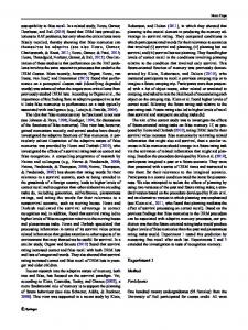
6. Application Exploration To explore the benefits of the novel memory core, the Scale Invariant Feature Transform (SIFT, [15]), a complex and very computational intensive image processing algorithm, has been used. This algorithm finds interesting points in an image and describes them as features (so-called descriptors). These descriptors have the advantage that they are invariant to scaling and orientation as well as partially invariant to distortion and illumination changes. These properties make them beneficial for object recognition applications. The algorithm has been implemented following the description in [15]. Through blurring and resampling of the input image, several intermediate images are created. The differences between the generated images deliver minima and maxima, which are taken as so-called keypoints. Out of these the best are used as descriptors. The found descriptors are then marked as red circles in the output image, as can be seen in Figure 9. For parallelization, the input image can be divided into several tiles which can be processed independently. To allow all processors access to the input image, a global shared memory is necessary. All intermediate images of the
11
Figure 9: SIFT descriptors marked in output image.
same tile are kept in the local memories of the processors as more calculations are done with them.
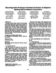
7. Integration and Results The test system is implemented on a Xilinx Virtex-5 LX110 FPGA and uses two Xilinx Microblaze softcore processors for the computation. Each one of them has 128KB of local block RAM. The input image is received over a video graphics array (VGA) connection and written directly into the DDR2 memory by the use of the Xilinx IPCores vga in, de gen, and video to vfbc. There, the data can be accessed by the processors through the memory controller. As only a specific part of the memory is assigned to a processor, this leads to the image segmentation, where one processor has access to the upper part of the image and the other has access to the lower part of the image. For the output the module Xilinx xps tft is used. It uses a given memory area as a framebuffer and outputs it over digital visual interface (DVI) as an image on an external display. To speed up the calculation a hardware accelerated finite response filter was added to the system. It allows faster calculation of Gaussian filtered images. The complete system can be seen in Figure 10. With the help of the memory core, the image input and output can be handled as seen in Figure 11. Each processor can read data from the input image as well as write data to the XPS TFT address range to output the results on the external display. At first, the performance overhead of the new MPI layer was evaluated. The achieved throughput was compared to the values of [2]. In addition to that, tests were run using the MPI layer with PLB access to the memory. The results can be seen in Figure 12 for writes and in Figure 13 for reads. The write throughput of the memory core access with more than 128 bytes is reduced to about 55% when using the MPI layer. With more than 128 bytes transferred, it is faster than PLB with the MPI layer and with more than 256 bytes transferred it is even faster than direct PLB access. Reading data is not as much affected as writing and still manages to achieve more than 80% of the throughput at a higher number of bytes. Both PLB accesses are outperformed when more than 64 bytes are transferred to the DDR memory.
12
International Journal of Reconfigurable Computing Table 2: Resource utilization of the individual components. MB0
Component
FIR 2D
Microblaze Accelerator Memory core MPMC Video I/O On-chip communication
2 3
1
4
MB1
1
Percentage of whole system 4.9 21.0 14.7 13.6 5.7 33.5
7
5 6
XPS TFT
Memory core
VGA input
1
: superswitch
x
: subswitch
MB
Number of Virtex 5 LUTs 1746 7470 5206 4835 2039 11873
: microblaze processor
FIR 2D : finite response filter
Figure 10: Overview of the test system.
XPS TFT
VGA input
480 lines 1024∗32 bit
480 lines 1024∗32 bit
1920 1920 KB KB DDR2 memory Memory core
Figure 11: Memory core as Framebuffer.
For the SIFT algorithm an input image with a resolution of 640 × 480 pixels is used. Each pixel uses 32 bits of data and to ease the addressing of single lines 1024 pixels per line are saved in the memory. All pixels not belonging to the image are forced to the value 0. Thus one image in the memory needs 1920 KB of space. For the memory core access this means the allocation of 15 blocks per processor for the input and 15 blocks per processor for the output of data.
A segment size of 64 × 120 pixels was chosen. As the image is read line by line, a good read throughput of more than 30 MB/s can be achieved this way. Bigger segments would allow even higher throughput rates but are limited by the size of the local memory of the processors. Getting a new image segment from the shared memory is about 3times faster when using the memory core: 2.79 ms with PLB access versus 0.89 ms with memory core access. As a result the found descriptors are marked in the output image. One pixel would be enough but for better highlighting a circle around the found pixel is used. This scenario does not really fit the memory access through the memory core because only small amounts of data need to be transferred. In this case writing one single pixel takes 3.42 µs against 0.63 µs with PLB access. With a circle for better emphasis, the times increase to 58.14 µs and 10.71 µs, respectively. In Table 2 the resource utilization of the individual components can be seen. The memory core with two address generators needs only around 1% more look-up tables (LUTs) than the MPMC. The processing elements (Microblaze and accelerator) take up about one-third of the whole resources as does the on-chip communication. Components concerning the memory system need a little less than 30 percent and the rest of the resources is shared between the video I/O modules as well as the general parts such as clock and reset generation.
8. Conclusions and Outlook In this paper the hardware architecture and the software abstraction layer of an adaptive multiclient Network-onChip memory core have been presented. The memory core dynamically manages the varying number of processing elements within a reconfigurable MPSoC and the therefore varying memory requirements. For the memory access a scheduling algorithm based on dynamic priorities is used. Due to its modular structure resource requirements can be adapted to achieve a good tradeoff between performance and area based on the application requirements, for example, by selecting the appropriate number of address generators. Furthermore, the memory core can easily be modified to support other NoCs or to be ported to other FPGAs, such as Altera. The software abstraction layer introduced in this paper is based on MPI. It eases the use of the memory core by hiding the complexity and therefore the low-level commands for accessing the memory core.
International Journal of Reconfigurable Computing
13 Write throughput
100
MB/s
80 60 40 20 0 4
8
16
32
64 128 256 Number of bytes
PLB Memory core
512
1024
2048
4096
PLB with MPI layer Memory core with MPI layer
Figure 12: Comparison of the achievable write throughput in MB/s at 125 Mhz: Star-Wheels NoC and adaptive memory core versus PLB and Xilinx MPMC controller, both with and without MPI layer.
Read throughput 80
MB/s
60 40 20 0
4
8
16
32
64 128 256 Number of bytes
PLB Memory core
512
1024
2048
4096
PLB with MPI layer Memory core with MPI layer
Figure 13: Comparison of the achievable read throughput in MB/s at 125 Mhz: Star-Wheels NoC and adaptive memory core versus PLB and Xilinx MPMC controller, both with and without MPI layer.
The correct functionality of the memory core was explored using a complex image processing application. Performance results were measured on a Virtex-5 FPGA. It was shown that for higher amounts of data, as needed for example, in image processing applications, the adaptive memory core provides a higher throughput compared to using the MPMC controller via the standard PLB interface provided by Xilinx. Furthermore, it supports up to 16 processor cores, while the MPMC only allows up to 8 connections. Even with the overhead of the software abstraction layer a higher performance for higher amounts of data was achieved compared to accessing the MPMC via the PLB interface. Future work is to develop an administrative subcomponent or separate controller whose functionality goes beyond the capabilities of the access controller. This component will make it possible to monitor the allocated blocks of the different address generators and allow the allocation of shared memory regions to support the above-mentioned MPI feature to define windows to work on the same data set with several processors.
Acknowledgments The authors would like to thank Andreas Stuckert from Fraunhofer IOSB for supporting them with the SIFT algorithm. This work received financial support by Fraunhofer IOSB and by the Concept for the Future of the Karlsruhe Institute of Technology (KIT) within the framework of the German Excellence Initiative.
References [1] D. G¨ohringer, Flexible design and dynamic utilization of adaptive scalable multi-core systems [Ph.D. thesis], Dr. Hut M¨unchen, 2011. [2] D. G¨ohringer, L. Meder, M. H¨ubner, and J. Becker, “Adaptive multi-client network-on-chip memory,” in Proceedings of the International Conference on ReConFigurable Computing and FPGAs (ReConFig ’11), pp. 7–12, Cancun, Mexico, 2011. [3] MPI, “A message-passing interface standard,” Version 2.2, Message Passing Interface Forum, September 2009, http:// www.mpi-forum.org/.
14 [4] Xilinx, “LogiCORE IP Processor Local Bus (PLB) v4.6 (v1.05a),” DS531, September 2010, http://www.xilinx.com/. [5] Xilinx, “LogiCORE IP Multi-Port Memory Controller (MPMC) (v6.01.a),” DS643, July 2010, http://www.xilinx .com/. [6] N. Voros, A. Rosti, and M. H¨ubner, Dynamic System Reconfiguration in Heterogeneous Platforms: The MORPHEUS Approach, Springer, 2009. [7] B. B. Fraguela, J. Renau, P. Feautrier, D. Padua, and J. Torrellas, “Programming the FlexRAM parallel intelligent memory system,” in Proceedings of the 9th ACM SIGPLAN Symposium on Principles and Practice of Parallel Programming (PPoPP ’03), pp. 49–60, New York, NY, USA, June 2003. [8] R. Buchty, O. Mattes, and W. Karl, “Self-aware memory: managing distributed memory in an autonomous multi-master environment,” in Proceedings of the 21st International Conference on Architecture of Computing Systems (ARCS ’08), pp. 98– 116, Dresden, Germany, February 2008. [9] Z. Dai and J. Zhu, “A bursty multi-port memory controller with quality-of-service guarantees,” in Proceedings of the 9th International Conference on Hardware/Software Codesign and System Synthesis (CODES+ISSS 111), pp. 21–28, Taipei, Taiwan, October 2011. [10] W. Kritikos, A. Schmidt, R. Sass, E. K. Anderson, and M. French, “Redsharc: a programming model and on-chip network for multi-core systems on a programmable chip,” International Journal of Reconfigurable Computing, vol. 2012, Article ID 872610, 11 pages, 2012. [11] K. Goossens, J. Dielissen, and A. Rˇadulescu, “Æthereal network on chip: concepts, architectures, and implementations,” IEEE Design and Test of Computers, vol. 22, no. 5, pp. 414–421, 2005. [12] F. Lemonnier, P. Millet, G. M. Almeida et al., “Towards future adaptive multiprocessor systems-on-chip: an innovative approach for flexible architectures,” in Proceedings of the International Conference on Embedded Computer Systems: Architectures, Modeling, and Simulation (SAMOS XII), Samos, Greece, July 2012. [13] Xilinx, “Fast Simplex Link (FSL) Bus (v2.11a),” DS449, June 2007, http://www.xilinx.com/. [14] S. Werner, O. Oey, D. G¨ohringer, M. H¨ubner, and J. Becker, “Virtualized on-chip distributed computing for heterogeneous reconfigurable multi-core systems,” in Proceedings of the Design, Automation & Test in Europe (DATE ’12), pp. 280–283, Dresden, Germany, March 2012. [15] D. G. Lowe, “Distinctive image features from scale-invariant keypoints,” International Journal of Computer Vision, vol. 60, no. 2, pp. 91–110, 2004.
International Journal of Reconfigurable Computing
International Journal of
Rotating Machinery
Engineering Journal of
Hindawi Publishing Corporation http://www.hindawi.com
Volume 2014
The Scientific World Journal Hindawi Publishing Corporation http://www.hindawi.com
Volume 2014
International Journal of
Distributed Sensor Networks
Journal of
Sensors Hindawi Publishing Corporation http://www.hindawi.com
Volume 2014
Hindawi Publishing Corporation http://www.hindawi.com
Volume 2014
Hindawi Publishing Corporation http://www.hindawi.com
Volume 2014
Journal of
Control Science and Engineering
Advances in
Civil Engineering Hindawi Publishing Corporation http://www.hindawi.com
Hindawi Publishing Corporation http://www.hindawi.com
Volume 2014
Volume 2014
Submit your manuscripts at http://www.hindawi.com Journal of
Journal of
Electrical and Computer Engineering
Robotics Hindawi Publishing Corporation http://www.hindawi.com
Hindawi Publishing Corporation http://www.hindawi.com
Volume 2014
Volume 2014
VLSI Design Advances in OptoElectronics
International Journal of
Navigation and Observation Hindawi Publishing Corporation http://www.hindawi.com
Volume 2014
Hindawi Publishing Corporation http://www.hindawi.com
Hindawi Publishing Corporation http://www.hindawi.com
Chemical Engineering Hindawi Publishing Corporation http://www.hindawi.com
Volume 2014
Volume 2014
Active and Passive Electronic Components
Antennas and Propagation Hindawi Publishing Corporation http://www.hindawi.com
Aerospace Engineering
Hindawi Publishing Corporation http://www.hindawi.com
Volume 2014
Hindawi Publishing Corporation http://www.hindawi.com
Volume 2010
Volume 2014
International Journal of
International Journal of
International Journal of
Modelling & Simulation in Engineering
Volume 2014
Hindawi Publishing Corporation http://www.hindawi.com
Volume 2014
Shock and Vibration Hindawi Publishing Corporation http://www.hindawi.com
Volume 2014
Advances in
Acoustics and Vibration Hindawi Publishing Corporation http://www.hindawi.com
Volume 2014